a novel approach to 3d laser scanning - araa novel approach to 3d laser scanning david wood , ......
TRANSCRIPT

A Novel Approach to 3D Laser Scanning
David Wood∗, Mark BishopOcular Robotics, Sydney, Australia
{d.wood, m.bishop}@ocularrobotics.com
Abstract
This paper presents a novel 3D laser scannerand compares its performance to that of a rangeof approaches presently in-use. Each of the al-ternatives are discussed with respect to a selec-tion of key performance metrics, and the newscanner is also analysed within this context.Examples are then presented where the impactof these performance metrics on real-world ap-plications are illustrated through a simulation,and the new scanner is demonstrated to providesignificant advances over existing technologies.
1 Introduction
One of the most ubiquitous tools for modern computerperception is the scanning LiDAR. These tools enableengineers to build two or three dimensional models ofthe world which can be used for navigation, obstacle de-tection and avoidance, target tracking or many otherapplications. For the past decade, researchers havebeen exploring ways to move beyond the traditional 2-dimensional planar laser scanner and effectively acquire3-dimensional point clouds. For some applications suchas Surmann et. al. [2001], the goal has been to buildstructured models of the world, for others [Mertz etal., 2012] the goal is to detect, track and classify ob-jects within the world. Work is also being done at ahigher level, on the analysis of generic 3D point clouddata [Douillard et al., 2011]. As autonomous systemsgain higher levels of intelligence and the ability to rea-son on perceived surroundings more effectively, then itbecomes desirable to acquire commensurately informa-tion rich data on these surroundings. Given the resolu-tion and accuracy limitations of radar and stereo visionbased systems, 3D LiDARs remain the sensor of choicefor generating such data.
In Section 2, we will discuss a number of such sensorsin-use for various applications in robotics. These sensorswill be compared with respect to a basic set of perfor-mance metrics. In Section 3, we will present our novel
sensor design, the Ocular Robotics RE05. This sensorenables the flexible acquisition of 3D laser data. The sen-sor can be re-configured on the fly to a significantly widerrange of resolution and scan speed behaviours than ex-isting sensor approaches. Section 4 will discuss in detailthe performance capabilities of the new scanner. Sec-tion 5 then discusses the performance of the RE05 andother sensors from Section 2 with respect to a numberof simulated application examples. This section showsthe impact of the variation in performance metrics fromearlier sections on simulated real-world problems.
2 Comparison With ExistingApproaches
In this section, the performance of a number of ap-proaches to 3D LiDAR will be examined. Specific exam-ples of each of the styles of 3D LiDAR have been selected,based on identified applications in robotics. For each ofthe classes of actuated scanner, we have identified com-mercially available packages to examine, as these are thebest documented in their performance when comparedto the homebrew systems developed internally in manyrobotics laboratories.
2.1 Sensor Categories
The first of these is the actuated 2D laser, where a pla-nar laser scanner is actuated to rotate through a thirdaxis to sweep an area with the scan plane. This hasbeen a very common approach for robotics applicationsparticularly in the past when there were very few otheroptions. Frequently these systems used one or more SickLMS 2xx devices with the actuating component beingfabricated by the end user as seen in [Mertz et al., 2012;Pervolz et al., 2006; Surmann et al., 2001]. The mostcommon configuration is the ‘nodding’ configuration, asillustrated in Figure 1. There are commercially availableversions of such systems, such as the Fraunhofer IAS sen-sors. In this comparison the 3DLS-N and the 3DLS-K2will be used.
Another common approach are dedicated 3D LiDAR
Proceedings of Australasian Conference on Robotics and Automation, 3-5 Dec 2012, Victoria University of Wellington, New Zealand.
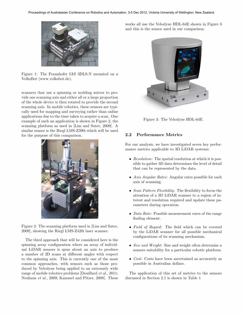
Figure 1: The Fraunhofer IAS 3DLS-N mounted on aVolksBot (www.volksbot.de).
scanners that use a spinning or nodding mirror to pro-vide one scanning axis and either all or a large proportionof the whole device is then rotated to provide the secondscanning axis. In mobile robotics, these sensors are typi-cally used for mapping and surveying rather than onlineapplications due to the time taken to acquire a scan. Oneexample of such an application is shown in Figure 2, thescanning platform as used in [Lim and Suter, 2009]. Asimilar sensor is the Riegl LMS-Z390i which will be usedfor the purpose of this comparison.
Figure 2: The scanning platform used in [Lim and Suter,2009], showing the Riegl LMS-Z420i laser scanner.
The third approach that will be considered here is thespinning array configuration where an array of individ-ual LiDAR sensors is spun about an axis to producea number of 2D scans at different angles with respectto the spinning axis. This is currently one of the mostcommon approaches, with sensors such as those pro-duced by Velodyne being applied to an extremely widerange of mobile robotics problems [Douillard et al., 2011;Neuhaus et al., 2009; Kammel and Pitzer, 2008]. These
works all use the Velodyne HDL-64E shown in Figure 3and this is the sensor used in our comparison.
Figure 3: The Velodyne HDL-64E.
2.2 Performance Metrics
For our analysis, we have investigated seven key perfor-mance metrics applicable to 3D LiDAR systems:
• Resolution: The spatial resolution at which it is pos-sible to gather 3D data determines the level of detailthat can be represented by the data.
• Axis Angular Rates: Angular rates possible for eachaxis of scanning.
• Scan Pattern Flexibility : The flexibility to focus theattention of a 3D LiDAR scanner to a region of in-terest and resolution required and update these pa-rameters during operation.
• Data Rate: Possible measurement rates of the rangefinding element.
• Field of Regard : The field which can be coveredby the LiDAR scanner for all possible mechanicalconfigurations of its scanning mechanism.
• Size and Weight : Size and weight often determine asensors suitability for a particular robotic platform.
• Cost : Costs have been ascertained as accurately aspossible in Australian dollars.
The application of this set of metrics to the sensorsdiscussed in Section 2.1 is shown in Table 1
Proceedings of Australasian Conference on Robotics and Automation, 3-5 Dec 2012, Victoria University of Wellington, New Zealand.

AxisResolution Angular Scan Pattern Data Field of Size(mm) IP Cost(Az x El) Rates Flexibility Rate Regard Rating (AUD)
(Az x El) (Az x El) Weight (kg)0.250 Az 19 Hz Az El. Rate 1000 Az 166mm H
Fraunhofer 0.250 El 0.04Hz El El. Range7.6kHz
1240 El 286mm W3DLS-N 1.00 Az 75Hz Az Az. Resolution 1800 Az 166mm D
65 $11,200
1.00 El 0.3Hz El (0.250 − 1.00)13.6 kHz
1240 El 7.4 kgNotes All parameters quoted here are for the 3DLS-N using a Sick LMS200.
The 3DLS-N allows the varying of the elevation scan rate, the elevation scan region and azimuthscan resolution to 1.00, 0.50 or 0.250.
As the actuated axis is close and perpendicular to the elevation scanning axis the maximumelevation field of regard is only 1240 seen directly in front of the 3DLS-N and reduces to close to 00
at either side.0.250 Az 0.03Hz Az 3600 Az 320mm H
Fraunhofer 0.250 El 19Hz ElAz. Rate 15.2kHz
2000 El 500mm W3DLS-K2 4.00 Az 1.67Hz Az
El. Resolution3600 Az 500 mm D
65 $20,000
1.00 El 75Hz El(0.250 − 1.00) 27.2 kHz
3600 El 13.0 kgNotes All parameters quoted here are for the 3DLS-K2 using two Sick LMS200s with their scanning
axes positioned horizontally.The 3DLS-K2 allows the varying of the azimuth scan rate between 0.03Hz and 1.67Hz and the
elevation resolution at 1.00, 0.50 and 0.250.El. Rate 463mm H
Riegl 0.0010 Az 0.042Hz Az Az. Rate 3600 Az 210mm øLMS-Z390i 0.0010 El 20Hz El El. Range
11kHz800 El
64 $200,000
Az. Range 15.0 kgNote The LMS-Z390i allows varying the elevation scan rate between 1Hz and 20Hz in rotating mirror
mode and allows adjustment of the elevation range in oscillating mirror mode. Azimuth scan rangecan be varied between 00 and 3600 with azimuth scan rates between 0.00003Hz and 0.042Hz.
250mm HVelodyne 0.090 Az 15Hz Az
Az. Rate 1300 kHz3600 Az
200mm ø 67 $75,000HDL-64E 0.40 El - El 26.80 El
13.0 kgNote The HDL-64E allows the azimuth scan rate to be varied between 5Hz and 15Hz. It has no
elevation scan capability as it has an array of 64 LiDARs at approximately 0.40 intervals across its26.80 elevation field.
Ocular Full Field 300mm HRobotics
0.010 Az 20Hz AzBounded El. 30 kHz
3600 Az150mm W/D 67 $22,000
RE050.010 El 3Hz El
Region Scan700 El
2.5 kgNote Details of the performance and scan patterns are discussed in Section 4
Table 1: The comparison table for existing commercially available 3D LiDAR systems.
3 RE05 System
This section will discuss the design and implementationof the RE05 laser scanner, as shown in Figure 5. In Sec-tion 3.1, we will examine the mechanics of the RE05,and the aspects of the drive mechanism which allow forits unique performance. This is followed by a discus-sion of the electrical aspects of the system (Section 3.2),focussing on motor control and interfacing. Lastly, Sec-tion 3.3 is a brief discussion of the software interfaceapproach, highlighting the flexibility which can be ob-
tained through a relatively simple UDP interface.
3.1 Mechanical Design
The core of the RE05 system is the unique mechanicaldesign of the optical pointing head, shown in Figure 6.There are three main components to this system. Firstly,the laser module itself is a 1D OEM laser range finder. Itsupports sample rates of up to 10 KHz with intensity re-turns, and 30 KHz with range-only measurements. Nom-inal maximum range is 30m to a 10% reflectivity target,and 200m to a retro-reflector. The beam-path for this
Proceedings of Australasian Conference on Robotics and Automation, 3-5 Dec 2012, Victoria University of Wellington, New Zealand.
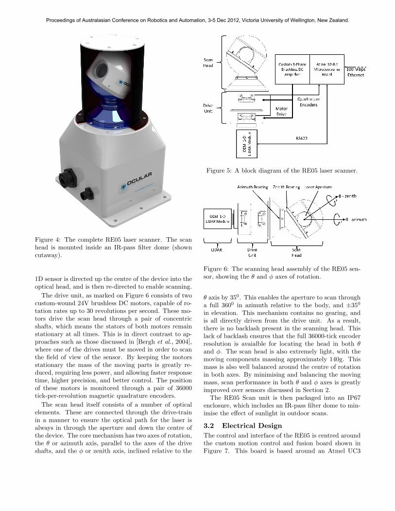
Figure 4: The complete RE05 laser scanner. The scanhead is mounted inside an IR-pass filter dome (showncutaway).
1D sensor is directed up the centre of the device into theoptical head, and is then re-directed to enable scanning.
The drive unit, as marked on Figure 6 consists of twocustom-wound 24V brushless DC motors, capable of ro-tation rates up to 30 revolutions per second. These mo-tors drive the scan head through a pair of concentricshafts, which means the stators of both motors remainstationary at all times. This is in direct contrast to ap-proaches such as those discussed in [Bergh et al., 2004],where one of the drives must be moved in order to scanthe field of view of the sensor. By keeping the motorsstationary the mass of the moving parts is greatly re-duced, requiring less power, and allowing faster responsetime, higher precision, and better control. The positionof these motors is monitored through a pair of 36000tick-per-revolution magnetic quadrature encoders.
The scan head itself consists of a number of opticalelements. These are connected through the drive-trainin a manner to ensure the optical path for the laser isalways in through the aperture and down the centre ofthe device. The core mechanism has two axes of rotation,the θ or azimuth axis, parallel to the axes of the driveshafts, and the φ or zenith axis, inclined relative to the
Figure 5: A block diagram of the RE05 laser scanner.
Figure 6: The scanning head assembly of the RE05 sen-sor, showing the θ and φ axes of rotation.
θ axis by 350. This enables the aperture to scan througha full 3600 in azimuth relative to the body, and ±350
in elevation. This mechanism contains no gearing, andis all directly driven from the drive unit. As a result,there is no backlash present in the scanning head. Thislack of backlash ensures that the full 36000-tick encoderresolution is avaialble for locating the head in both θand φ. The scan head is also extremely light, with themoving components massing approximately 140g. Thismass is also well balanced around the centre of rotationin both axes. By minimising and balancing the movingmass, scan performance in both θ and φ axes is greatlyimproved over sensors discussed in Section 2.
The RE05 Scan unit is then packaged into an IP67enclosure, which includes an IR-pass filter dome to min-imise the effect of sunlight in outdoor scans.
3.2 Electrical Design
The control and interface of the RE05 is centred aroundthe custom motion control and fusion board shown inFigure 7. This board is based around an Atmel UC3
Proceedings of Australasian Conference on Robotics and Automation, 3-5 Dec 2012, Victoria University of Wellington, New Zealand.
family 32-bit microcontroller, running at a 66MHz coreclock. The UC3 interfaces to the host over a 100MBpsEthernet interface, and to a dual-chip motor control so-lution on the same board. The UC3 also communi-cates with the OEM laser ranger over a serial connec-tion and fuses the range readings with synchronised en-coder samples to produce range-bearing-elevation obser-vations. These observations are then transmitted overthe same 100MBps ethernet interface used for control,giving a single point-of-connection to the RE05.
The motion control solution is a 2-chip Magellan solu-tion produced by PMD. This chip closes a separate PIDcontrol loop around each of the axes at a rate of 6.15kHz. Although the control is independent at this level,higher-level co-ordination is implemented on the UC3 toensure synchronised behaviour of both axes within thescanner.
Figure 7: The RE05 control PCBs. Amplifier with itsheatsink on left. µP board on right.
3.3 Software Interface Design
The software interface to the RE05 is based on the UDPprotocol to minimise overheads and latency. OcularRobotics will publish the complete specification of thesoftware interface at a UDP level, enabling systems inte-grators to work directly with a well-known communica-tions standard and being completely agnostic to the hostoperating system or computing architecture. The inter-face is specifically designed to be minimal, there are 3classes of command with less than 10 commands in eachclass.
• RobotEye System Commands - These commandsenable the presence of RE05’s on a network to bedetected, and properties such as their IP addressand startup behaviour to be configured.
• Laser Management Commands - These commandsenable the direct management of the behaviour ofthe built-in laser module, specifying sample rates,averaging, min and max ranges, and other settings.
• Scan Pattern Commands - These 3 commands en-able the properties of a scan pattern to be config-ured, such as Azimuth rate, line spacing, and theboundaries for bounded-elevation and region scanmodes.
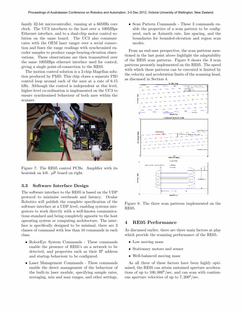
From an end-user perspective, the scan patterns men-tioned in the last point above highlight the adaptabilityof the RE05 scan patterns. Figure 8 shows the 3 scanpatterns presently implemented on the RE05. The speedwith which these patterns can be executed is limited bythe velocity and acceleration limits of the scanning head,as discussed in Section 4.
Figure 8: The three scan patterns implemented on theRE05.
4 RE05 Performance
As discussed earlier, there are three main factors at playwhich provide the scanning performance of the RE05.
• Low moving mass
• Stationary motors and sensor
• Well-balanced moving mass
As all three of these factors have been highly opti-mised, the RE05 can attain sustained aperture accelera-tions of up to 100, 0000/sec, and can scan with continu-ous aperture velocities of up to 7, 2000/sec.
Proceedings of Australasian Conference on Robotics and Automation, 3-5 Dec 2012, Victoria University of Wellington, New Zealand.

The eye operates in two distinct scan behaviours. Infull-field and bounded elevation scan modes, the eye ro-tates at a constant azimuth rate whilst scanning in araster pattern with a specified line resolution. In thisbehaviour the limit to the performance of the scanner isthe maximum allowable velocity. This limit is investi-gated in more detail in Section 4.1.
The other primary behaviour is piecewise linear mo-tion. This is the behaviour that is used to generate theregion scan mode. In this mode, the performance limit isthe acceleration of the aperture, and the aperture trajec-tories are triangular (constant acceleration). This styleof trajectory is analysed in detail in Section 4.2.
These two trajectory types also relate to the resolutionat which range samples are acquired. The links betweenthis resolution and the scan patterns being performedare discussed in more detail in Section 4.3.
4.1 Velocity Limited TrajectoryPerformance
The scan rates of the RE05 in full-field and bounded-elevation scan modes are limited by the peak velocityof the scan head itself. The highest-rate motion is thescanning of the entire head around the azimuth axis, slowrotation around the zenith axis then introduces the spiralpattern producing the diagonal line pattern shown inFigure 8. The rate limits for the two axes are 7, 2000/secfor azimuth motion and 5400/sec for zenith motion. Afull-field scan running at these rates would give a linespacing of approximately 10.50 per line between ±350 inelevation, and a full field refresh rate of 3Hz.
In bounded elevation scans, this refresh rate could beincreased, by maintaining the same elevation resolutionand decreasing the region of elevation to be scanned.The limiting case for this is a 2D line-scan pattern, wherethere is no azimuth motion at all. The scan elevationcan be anywhere within the range with no performancepenalty. For the line-scan behaviour mode, line rates of20Hz are possible.
These behaviours can be changed at any time, withthe responsiveness of the scan head being limited by the100, 0000/sec acceleration limit of the scan head. Thislimit enables the head to transition from stationary to afull-speed scan in approximately 75 mSec, and to tran-sition from full-speed scan to stopped at an arbitrarylocation within the field of view in 125 mSec.
4.2 Acceleration Limited TrajectoryPerformance
The scan rate of the eye in region scan mode is limitedby the acceleration capability of the scan head. Whenoperating in region scan mode, the head reverses direc-tion at the end of each line, so it’s behaviour can beapproximated as a sequence of point-to-point motions
where the eye comes close to a stop at each point. Figure9 shows the performance of the eye in a back-and-forthazimuth scan pattern of 2700 with 200 millisecond dwellsat each point. The noise in the acceleration trace is dueto some timing instability in the commercial motor con-troller used to perform these tests, and a soft tuning ofthe PID controller. The transition phase of each of thesemotions is a triangular velocity segment taking approx-imately 150 mSec.
Figure 9: The results of basic azimuth point-to-point motion testing. Note the peak accelerations ex-
ceeding −2× 1050/sec above sustained accelerations of
1× 1050/sec.
This type of behaviour represents the equivalent to a
Proceedings of Australasian Conference on Robotics and Automation, 3-5 Dec 2012, Victoria University of Wellington, New Zealand.

region-scan type behaviour. The limiting factor in thesemotions is the acceleration of the scan head. Under fullacceleration, the eye will take 2600 of motion to achievepeak velocity, requiring a scan pattern line width of 5200
to reach the velocity limit. We can therefore guaranteethat any region scan behaviour will be executed usingtriangular velocity trajectories, since the region windowcannot possibly be wider in azimuth than 3600.
Based on triangular trajectories such as these, withina region of angular width d, peak velocity during a linecan be calculated as:
Vpeak =√
2a× (d/2) (1)
giving a time to execute that line of:
T =d
Vpeak/2= 2
√d
a(2)
This behaviour is of great benefit when it is desirableto perform an adaptive region scan. As the width of theregion to scan grows larger, the time taken to scan thearea grows deterministically, linearly in elevation reso-lution and elevation range and sub-linearly in azimuthrange. This enables directed perception systems to makeeducated decisions regarding the best use of the sensor.
This deterministic relationship also provides an inter-esting limit. There will be many cases of region scans forwhich it is more efficient to run the eye in a bounded-elevation scan mode than to decelerate and accelerateat the end of each line. If running at peak velocity of7, 2000/sec, each line scan in full-field or bounded eleva-tion mode takes 50 msec. For an average acceleration of
1050/sec2, this corresponds to a region scan line width of
0.052×10⁵
2 = 1250. For any region scans wider than thislimit, higher line rates will be achieved by running theeye in bounded elevation mode and segmenting out theregion of interest.
4.3 Range Sample Density
The final component of RE05 performance which has notyet been discussed is the relationship between scan den-sity and motion speed. One of the great benefits of theRE05 system is the independence between sampling rateand scan speed. Since the parameters of the 1D laser aremanaged independently, the sample rate, averaging andinformation level can all be tailored to the particularscan of interest. The scan resolution in azimuth is de-termined by a combination of the sample rate and scanspeed.
The worst-case scenario for a 30kHz sample rate is tobe scanning at 7, 2000/sec, which gives an azimuth an-gular resolution of 0.090. If intensity values are required,the laser sample rate must be reduced to 10 kHz, giv-ing a worst-case resolution of 0.270. Again, the choice of
whether or not to acquire intensity information can bechanged at any time, enabling a system to intelligentlyselect between high-frequency data or more informativedata based on the task required.
The laser can also perform multiple-sample averagingin hardware. This is only available on the low-rate modewhich returns intensities, however when averaging 2 ormore samples, the laser will support underlying samplerates up to 15 kHz. This gives an output averaged sam-ple rate of 7.5 kHz or below when averaging in hardware.Where the processing power to do so exists, it will al-ways be more effective and informative to use a kernel-based filter over the high-rate data on a processing hostthan to average in the laser hardware. For applicationswhere this is not possible, it does provide a simpler op-tion which can result in a reduction in range uncertaintywithout imposing additional processing burdens on thehost.
5 Application-Based Comparison
In this section, the performance of the sensors will allbe compared based on a simulated real-world problem,The ability to acquire a 300mm diameter round targetsomewhere in the sensor’s field of regard. The targetin question is taken to be 90% reflective, and in orderto acquire the target we are specifying that at-least 3points in azimuth and 3 points in elevation are observedacross the target. This gives the minimal detection caseas shown in Figure 10.
Figure 10: Diagram illustrating the minimum required5 points on the target to be regarded as a ‘detection’.
The three measures used in this section are the rangeat which the target can be detected, the percentage ofthe total spatial volume over which the target can bedetected, and the time taken for each sensor to scan it’sfield of regard. For all sensors, we first investigate thesemetrics as taken for a scan of the full field of regard of thesensor, the results for which are presented in Section 5.1.If there is prior information regarding the location of thetarget, then the 3DLS-N, the LMS-Z390i and the RE05can all be configured to scan only the region of interest,and Section 5.2 discusses the simulated performance of
Proceedings of Australasian Conference on Robotics and Automation, 3-5 Dec 2012, Victoria University of Wellington, New Zealand.

these sensors when scanning a more restricted area.
5.1 Full field scans
In these comparisons, each sensor is scanning its full fieldof regard. For the sensors with tunable resolutions (allbar the Velodyne), it has been assumed that there isa level of prior knowledge about the size of the target,and that the sensor is configured to minimise the timespent scanning without reducing the range at which it ispossible to acquire the target.
Target Volume ScanSensor
Range (m) Ratio Time (sec)3DLS-N 68.7 63.4% 26.13DLS-K2 68.7 63.4% 75.79
LMS-Z390i 400 100% 450HDL-64E 42.9 4.59% 0.066
RE05 200 100% 87.5
Table 2: Results of full-field target detection test. Vol-ume Ratio is the percentage of the full field-of-regard ofthe sensor over which the target can be seen.
There are a number of interesting results seen in thistable. The first is the poor performance of the Velodyne,with it’s 0.40 elevation resolution proving to be a signifi-cant obstacle. The 3DLS modules both perform quitewell, however they cannot match the detection rangegiven by the RE05 and Riegl systems. Performing a scanadequate to detect such a small target has also provenquite a challenge for these sensors. The long scan timesexhibited by the 3DLS-K2, RE05 and Riegl are mostlydue to the high-resolution scan requirements limiting themotion speed.
5.2 Limited field scans
Three of the above five sensors allow a level of customi-sation of the scan pattern. For the 3DLS-N the scanrange can be limited in the elevation axis to a smallerregion of regard. For the LMS-Z390i, the scan area ofboth axes can be limited. The publicly available docu-mentation for this module does not specify the line-scanrates the system is capable of in oscillating mirror mode,so we shall assume the Riegl remains in rotating mirrormode with a 20Hz refresh rate. For the RE05, the timetaken to scan the region is calculated using Equation 2and the desired line density.
We assume for this that the position of the target isknown to an accuracy of ±5 times the target diameter,and that we are happy to only partially record the targetat short ranges, so the region to be scanned is a squareregion 10 times the target’s apparent size at the maxi-mum detection range identified in Section 5.1.
Again, this section shows interesting results. For theRiegl sensor, the bounded scan was still time-limited by
Region ScanSensor
Scanned Time (mS)1000 Az
3LDS-N2.50 El
173
0.430 AzLMS-Z390i
800 El560
0.860 AzRE05
0.860 El76
Table 3: Region scan target detection test.
the speed of rotation about the azimuth axis. Even whenthe region to be scanned is reduced to less than 0.50,the Riegl is still the slowest scanner being studied. TheRE05 has demonstrated that the use of the region scanmode in this application results in a substantial timesaving, even at the high scan resolutions being produced.
5.3 Discussion
The simulations above in conjunction with Table 1 showthat the RE05 fills a vacant niche in the 3D laser scan-ners presently on offer. It offers a completely unpar-allelled level of programmability of scan region, withTable 3 showing the substantial improvements in scantimes possible by restricting the scan region appropri-ately. It also offers much greater flexibility of resolutionwhen compared to existing sensors, with the azimuth andelevation resolutions both programmable down to an ex-tremely fine resolution. This flexibility is supported byextremely high dynamic performance due to the mechan-ical design of the scanning head as discussed in Section3.1.
The RE05 therefore fills an important nice within thestable of 3D LiDAR sensors currently on the market.The flexibilty will offer a previously unavailable oppor-tunity to gather information about adaptable specificregions within a sensor’s field of regard. This region-specific information can be gathered at higher resolutionand more rapidly than is possible with existing technolo-gies.
6 Conclusions
This paper has presented a novel 3D LiDAR system, theOcular Robotics RE05. This scanner was benchmarkedagainst a range of existing commercially available scan-ners, chosen to represent a cross-section of 3D LiDARsolutions. The existing approaches were compared tothe RE05 over a range of performance metrics, and werealso discussed with respect to a real world problem, de-tecting a circular target of known size. In this analysis,the flexibility of the RE05 was demonstrated to provideconsiderable improvements over existing technologies inthe acquision of region scans. The RE05 was also shown
Proceedings of Australasian Conference on Robotics and Automation, 3-5 Dec 2012, Victoria University of Wellington, New Zealand.

to be unique in its capability to provide high perfor-mance whilst being capable of adapting resolution andscan speeds intelligently to the task at hand.
References
[Bergh et al., 2004] C. Bergh, L. Matthies, andB. Kennedy. A compact and low power two-axisscanning laser rangerfinder for mobile robots. Tech-nical report, DSpace at Jet Propulsion Laboratory[http://trs-new.jpl.nasa.gov/dspace-oai/request](United States), 2004.
[Douillard et al., 2011] B. Douillard, J. Underwood,N. Kuntz, V. Vlaskine, A. Quadros, P. Morton,and A. Frenkel. On the segmentation of 3d lidarpoint clouds. In Proceedings of the 2011 IEEE In-ternational Conference on Robotics and Automation(ICRA), 2011.
[Kammel and Pitzer, 2008] S. Kammel and B. Pitzer.Lidar-based lane marker detection and mapping. In2008 IEEE Intelligent Vehicles Symposium, 2008.
[Lim and Suter, 2009] Ee Hui Lim and David Suter.3d terrestrial lidar classifications with super-voxelsand multi-scale conditional random fields. Computer-Aided Design, 41(10):701 – 710, 2009.
[Mertz et al., 2012] Christoph Mertz, Luis E. Navarro-Serment, Robert MacLachlan, Paul Rybski, AaronSteinfeld, Arne Suppe, Christopher Urmson, NicolasVandapel, Martial Hebert, Chuck Thorpe, David Dug-gins, and Jay Gowdy. Moving object detection withlaser scanners. Journal of Field Robotics, 2012.
[Neuhaus et al., 2009] F. Neuhaus, D. Dillenberger,J. Pellenz, and D. Paulus. Terrain drivability analysisin 3d laser range data for autonomous robot naviga-tion in unstructured environments. In Proceedings ofthe 2009 IEEE Conference on Emerging Technologies& Factory Automation (ETFA )., 2009.
[Pervolz et al., 2006] Kai Pervolz, Hartmut Surmann,and Stefan May. 3d laser scanner for tele-explorationrobotic systems. In Proceedings of the InternationalWorkshop on Safety, Security and Rescue Robotics(SRRR), August 2006.
[Surmann et al., 2001] Hartmut Surmann, Kai Linge-mann, Andreas Nuchter, and Joachim Hertzberg. A3d laser range finder for autonomous mobile robots.In Proceedings of the 32nd International Symposiumon Robotics (ISR), 2001.
Proceedings of Australasian Conference on Robotics and Automation, 3-5 Dec 2012, Victoria University of Wellington, New Zealand.