a novel cosmic ray tagger system for liquid argon tpc ... · a novel cosmic ray tagger system for...
TRANSCRIPT
Article
A Novel Cosmic Ray Tagger System for Liquid ArgonTPC Neutrino DetectorsM. Auger a, M. Del Tutto b, A. Ereditato a, B. Fleming c, D. Goeldi a, E. Gramellini c, R. Guenette b,W. Ketchum d, I. Kreslo a, A. Laube b, D. Lorca∗a, M. Luethi a, C. Rudolf von Rohr a,J. R. Sinclair a, S. R. Soleti b, M. Weber a
a Laboratory for High Energy Physics, Albert Einstein Center for Fundamental Physics, University of Bern,CH-3012, Switzerland
b University of Oxford, Oxford, OX1 3RH, United Kingdomc Yale University, New Haven, CT, 06520, USAd Fermi National Accelerator Laboratory, Batavia, Illinois 60510, USA* E-mail: [email protected]
Version December 15, 2016 submitted to Instruments; Typeset by LATEX using class file mdpi.cls
Abstract: The Fermilab Short Baseline Neutrino (SBN) program aims to observe and reconstructthousands of neutrino-argon interactions with its three detectors (SBND, MicroBooNE andICARUS-T600), using their hundred of tonnes Liquid Argon Time Projection Chambers to performa rich physics analysis program, in particular focused in the search for sterile neutrinos. Giventhe relatively shallow depth of the detectors, the continuos flux of cosmic ray particles whichcrossing their volumes introduces a constant background which can be falsely identified as partof the event of interest. Here we present the Cosmic Ray Tagger (CRT) system, a novel technique totag and identify these crossing particles using scintillation modules which measure their time andcoordinates relative to events internal to the neutrino detector, mitigating therefore their effect in theevent tracking reconstruction.
Keywords: Neutrino detectors; Particle identification methods; SiPM; background rejection
1. Introduction
The Fermilab Short Baseline Neutrino (SBN) program was proposed by three internationalcollaborations to accomplish a wide spectrum of physics research. Once the program is completed,it will perform sensitive searches for νe appearance and νµ disappearance, it will also study theneutrino-argon cross section with millions of interactions using the Booster Neutrino Beam (BNB) atFermilab [1]. These studies are expected to solve the currently unexplained low energy event excessobserved by LSND [2] and later confirmed by MiniBooNE [3], which could be interpreted by theoriesthat extend the Standard Model of Particles and Interactions with additional "sterile" neutrinos or thepresence of a non-observed-yet electromagnetic background.
The program is composed of the currently running MicroBooNE detector, a 170 t LiquidArgon (LAr) Time Projection Chamber (TPC) with charge-collection readout [4], located 470 m awayfrom the BNB primary target. Besides this, the 112 t Short Baseline Near Detector (SBND) [5] and600 t ICARUS T-600 detector [6], both LArTPCs, are respectively located at 110 m and 600 m awayfrom the BNB target. The construction of the SBN detectors is expected to be completed in 2017. The
∗Corresponding author
Submitted to Instruments, pages 1 – 10 www.mdpi.com/journal/instruments
arX
iv:1
612.
0461
4v1
[ph
ysic
s.in
s-de
t] 1
4 D
ec 2
016
Version December 15, 2016 submitted to Instruments 2 of 10
MicroBooNE collaboration finished the commissioning of the detector in the Summer of 2015 and hasalready collected neutrino interactions corresponding to about 4.0×10²⁰ protons on target, more thanhalf of the total expected for three years running.
Due to the shallow depth of the detectors’ location (∼6 meters underground), these arecontinuously exposed to a flux of background cosmic ray particles. At ground level, the mostabundant of these cosmic ray particles are muons, produced in the decay of pions and kaons [7].
In a typical neutrino-argon interaction in the LArTPCs, charged particles release their energyin the medium as described by the Bethe-Bloch formula. Due to the electric field present in the TPC,ionization electrons drift toward the anode where they are collected and the energy and momentum ofthe secondary particles is reconstructed. At the same time, primary scintillation light coming from theargon atoms is readout by a system of photomultiplier tubes immersed in the LAr volume, providingtiming information and an external trigger for the data acquisition (DAQ).
There exists a non-zero probability that a high energy cosmic ray muon crossing thereconstructed volume is misidentified as part of the neutrino interaction. Each muon track issurrounded by tracks of electrons and positrons originating from bremsstrahlung of delta-electrons.It has been estimated that around 8 muons cross the 2.33 m × 2.56 m × 10.37 m active volume in a2.2 ms DAQ window of MicroBooNE.
The Cosmic Ray Tagger (CRT) system presented here detects cosmic ray muons and measurestheir crossing time and coordinates relative to events internal to the TPC. It is a tool to mitigatethe cosmic ray background in the MicroBooNE and SBND detectors and to improve the statisticalsignificance of the physics measurements. The CRT systems will enable the MicroBooNE and SBNDexperiments to efficiently remove cosmogenic related activity from beam neutrino datasets, as well asallowing precision detector response characterization and calibration utilizing tagged cosmic muons.
We report here on the design and construction features of the CRT basic modules, as well aspresenting performance results.
2. Cosmic Ray Tagger System
The CRT system is composed of individual scintillator modules readout by SiliconPhotoMultipliers (see Section 2.1) with a maximum size of 4.1 m × 1.8 m × 2 cm and a maximumweight of 174 kg. Smaller-sized modules, 25% - 80% of the maximum size, will also be utilized tomatch to the specific geometry of the experiments at Fermilab. The module detection efficiency formuons has been measured to be higher than 95% with a coordinate resolution better than 1.8 cm (seeSection 3).
The modules are produced at the Laboratory for High Energy Physics (LHEP) in Bern and areshipped to Fermilab after a quality inspection. After assembly, modules and readout electronics (seeSection 2.3) are tested for proper operation. These tests verify the full readout chain, characterize theefficiency of cosmic muon detection in each module, and measure the data collection processing ineach channel.
2.1. Scintillator Module
Each scintillator module consists of a row of 16 mechanically joined 10.8 cm wide scintillatorstrips (Figure 1) placed side by side in a protective aluminum casing. The thickness of the case wallsis 2 mm; this provides the necessary mechanical stability. Strips are fixed within the module by a0.1 mm thick double-sided adhesive layer. The gap between two adjacent strips in a module is keptbelow 0.2 mm. The length of the modules varies from 2.3 m to 4.1 m, for three different widths:0.97 m, 1.75 m and 1.81 m.

Version December 15, 2016 submitted to Instruments 3 of 10
Figure 1. Scintillator module containing 16 scintillating strips. The external case is still to be mounted.
2.2. Scintillator Strip
Scintillating strips are extruded from a USMS-031 polystyrene-based mixture containing 1.5% ofDiphenylbenzene (PTP) and 0.04% of Bis(5-phenyl-2-oxazolyl)benzene (POPOP). The surface of thestrips is subjected to structural modification resulting in the formation of a highly-reflective whitelayer (Figure 2-left).
The scintillator has an emission maximum at 430 nm and a measured bulk attenuation length oflonger than 7.5 cm. In order to provide efficient and uniform collection of the scintillation light twowavelength shifting (WLS) fibers (Kuraray Y11(200)M, 1 mm diameter) are glued into two groovesin the long edges of each strip with a polysiloxane compound. The high elasticity of the compoundallows a displacement of the fiber along the strip without the risk of damaging its cladding. This, inturn, adds to the robustness of the assembled module. The modules can withstand moderate bendingduring transportation and manipulation without any appreciable deterioration of their properties.After gluing the fiber into the grooves, each strip is covered by a reflective aluminized Mylar tape toreduce photon losses and provide mechanical protection for the fibers as shown in Figure 2-right.
At the read out end the fibers are diamond-cut and fixed in dedicated plastic end-pieces. Theseend-pieces also provide precise alignment of the fiber with the photo-sensor. The opposite end of eachfiber is coated with aluminium by evaporation in vacuum forming a highly efficient reflecting mirror,which increases the light yield. Hamamatsu S12825-050P [8] Silicon PhotoMultipliers (SiPMs) areused to collect the scintillation light from each fiber. Two SiPMs are used to read out one scintillationstrip. Therefore, 32 photosensors are employed in one single module. Signals from the 32 SiPMs aresent to a Front-End electronics Board (FEB). Each FEB is mounted at the readout end of the modulesand connected to the SiPMs via 1 mm thick coaxial cables. Signal processing is performed in the FEBand readout for storage or higher-level triggering.
2.3. Front-End Board Electronics
The CRT FEB is designed to serve 32 SiPMs from one module (16 scintillator strips). The FEBprovides a bias voltage in the range of 40-90 V individually adjustable for each of the 32 SiPMs. Atthe same time it amplifies, shapes and digitizes the output signal of the photosensors. The FEB also
1 USMS-03 by UNIPLAST Inc, Vladimir, Russian Federation.

Version December 15, 2016 submitted to Instruments 4 of 10
SiPMs are on the back side of the PCB
Figure 2. Scintillator strips with wavelength shifter fibers glued into grooves along the strip longedges. The strip is covered by a high-reflectivity white layer. The scintillation light is collected byKuraray Y-11 wavelength shifting fibers and transmitted to the strip end where it is detected byHamamatsu S12825-050P SiPMs.
provides the signal coincidence from each pair of SiPMs from the same scintillator strip with thepossibility to trigger only on events that occurred in coincidence with another event in a differentFEB or group of FEBs. Furthermore, the FEB is able to generate a timestamp taking an input referencewith an accuracy of 1 ns. A detailed description of the FEB design and functionallity can be foundin [9].
2.4. Scintillator Plane
A scintillator plane consists of several scintillator modules arranged in two different layers andorthogonal directions, as shown in Figure 3. In this configuration, when a charged particle crosses theplane, it fires at least one strip per module.
By using the relative intensities of the SiPMs corresponding to the same timestamp provided bythe FEBs, the X-Y position of the particle crossing point can be computed (see Section 3). Two differentscintillator planes allow a crossing particle to be tagged, providing an "interaction vector". Thisinformation can then be extrapolated to the reconstruction algorithm of the LAr TPC, discriminatingany related event within the volume associated to the interaction vector that could be mistakenlyidentified as part of a neutrino interaction event.
The total number of scintillator modules to be built in Bern for the needs of the SBN program atFermilab amounts to 215, for a total covering surface of 538 m2.

Version December 15, 2016 submitted to Instruments 5 of 10
Figure 3. Cosmic Ray Tagger scintillator plane formed by two orthogonal layers of modules for X-Ycoordinate reconstruction.
3. Laboratory Tests
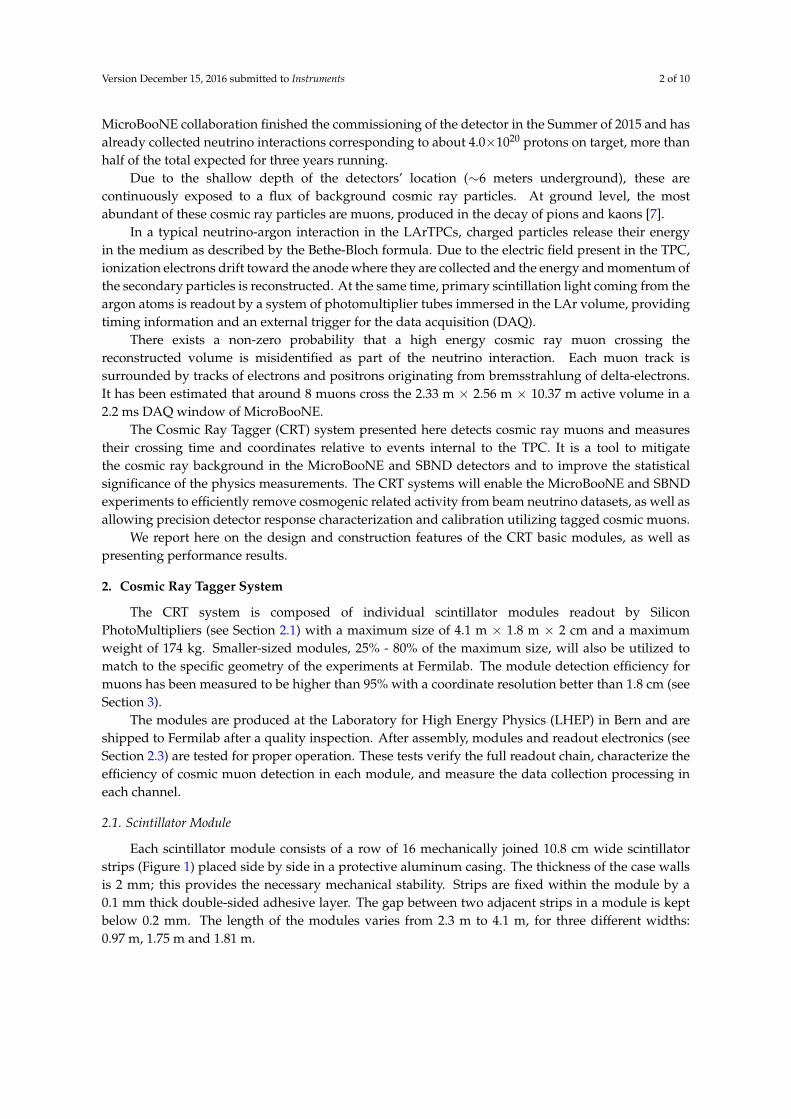
The first full-size 1.7 m × 5 m prototype CRT module was assembled and tested at LHEPin July-August 2015. Different studies were performed with this test module providing usefulinformation about the quality of the materials and the procedure for its construction. Thesame studies were conducted regularly on production modules (see Figure 4), obtaining similarperformance results.
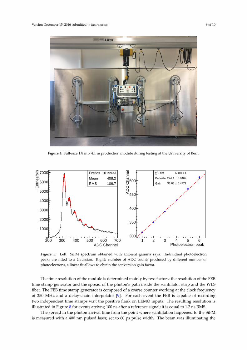
Before data taking the conversion gain of each individual photosensor must be accuratelydetermined. The SiPMs from each scintillator strip are calibrated using ambient background gammaevents which cross the module. From these events the spectrum shown in Figure 5-left is obtained, itcorresponds to the digital signal associated to the avalanche charge produced by a different numberof SiPM pixels. The conversion gain can be determined by fitting a Gaussian to the peaks and usingthe centroid position in a linear fit; an example is shown in Figure 5-right.
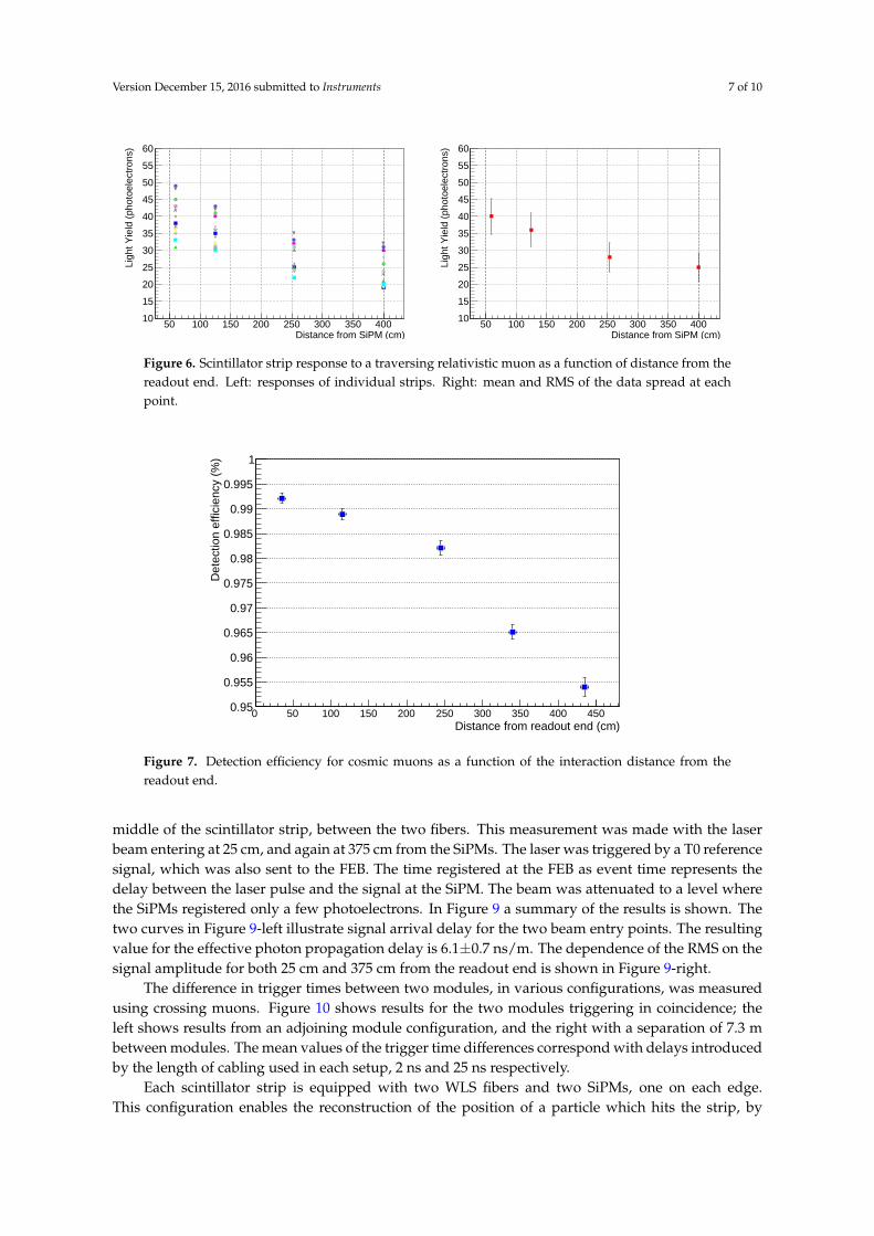
The variation in light yield for a relativistic muon traversing the 16 scinctillator strips of themodule at different distances from the readout end was also measured. The interaction distancewas determined with the aid of an external muon telescope composed of two scintillator paddleswith PMTs as photodetectors. The results for each of the 16 strips are shown in Figure 6-left, withFigure 6-right showing the mean and the RMS of the spread at each point.
As one can see, the light yield follows an exponential behaviour which can be fitted to extractthe attenuation length of the scintillator. This was measured to be 6.88± 0.01 m, which is longer thanthe maximum module length of 4.1 m, hence ensuring sufficient light yield.
The module detection efficiency for cosmic muons as a function of the distance from the readoutend was measured using the same external muon telescope as in the previous tests. Detectionefficiency is determined as the ratio between the number of muons detected by the telescope versusthose detected by the module. As shown in Figure 7, the efficiency is higher than 95% across theplane.
Version December 15, 2016 submitted to Instruments 6 of 10
Figure 4. Full-size 1.8 m x 4.1 m production module during testing at the University of Bern.
Entries 1019933
Mean 408.2
RMS 106.7
ADC Channel200 300 400 500 600 700
Ent
ries/
bin
0
1000
2000
3000
4000
5000
6000
7000 Entries 1019933
Mean 408.2
RMS 106.7
Photoelectron peak 1 2 3 4 5 6
AD
C C
hann
el
300
350
400
450
500
/ ndf 2χ 6.104 / 4
Pedestal 0.8469± 274.4
Gain 0.4772± 38.63
/ ndf 2χ 6.104 / 4
Pedestal 0.8469± 274.4
Gain 0.4772± 38.63
Figure 5. Left: SiPM spectrum obtained with ambient gamma rays. Individual photoelectronpeaks are fitted to a Gaussian. Right: number of ADC counts produced by different number ofphotoelectrons, a linear fit allows to obtain the conversion gain factor.
The time resolution of the module is determined mainly by two factors: the resolution of the FEBtime stamp generator and the spread of the photon’s path inside the scintillator strip and the WLSfiber. The FEB time stamp generator is composed of a coarse counter working at the clock frequencyof 250 MHz and a delay-chain interpolator [9]. For each event the FEB is capable of recordingtwo independent time stamps w.r.t the positive flank on LEMO inputs. The resulting resolution isillustrated in Figure 8 for events arrivng 100 ns after a reference signal; it is equal to 1.2 ns RMS.
The spread in the photon arrival time from the point where scintillation happened to the SiPMis measured with a 400 nm pulsed laser, set to 60 ps pulse width. The beam was illuminating the
Version December 15, 2016 submitted to Instruments 7 of 10
Distance from SiPM (cm)50 100 150 200 250 300 350 400
Ligh
t Yie
ld (
phot
oele
ctro
ns)
10
15
20
25
30
35
40
45
50
55
60
Distance from SiPM (cm)50 100 150 200 250 300 350 400
Ligh
t Yie
ld (
phot
oele
ctro
ns)
10
15
20
25
30
35
40
45
50
55
60
Figure 6. Scintillator strip response to a traversing relativistic muon as a function of distance from thereadout end. Left: responses of individual strips. Right: mean and RMS of the data spread at eachpoint.
Distance from readout end (cm)0 50 100 150 200 250 300 350 400 450
Det
ectio
n ef
ficie
ncy
(%)
0.95
0.955
0.96
0.965
0.97
0.975
0.98
0.985
0.99
0.995
1
Figure 7. Detection efficiency for cosmic muons as a function of the interaction distance from thereadout end.
middle of the scintillator strip, between the two fibers. This measurement was made with the laserbeam entering at 25 cm, and again at 375 cm from the SiPMs. The laser was triggered by a T0 referencesignal, which was also sent to the FEB. The time registered at the FEB as event time represents thedelay between the laser pulse and the signal at the SiPM. The beam was attenuated to a level wherethe SiPMs registered only a few photoelectrons. In Figure 9 a summary of the results is shown. Thetwo curves in Figure 9-left illustrate signal arrival delay for the two beam entry points. The resultingvalue for the effective photon propagation delay is 6.1±0.7 ns/m. The dependence of the RMS on thesignal amplitude for both 25 cm and 375 cm from the readout end is shown in Figure 9-right.
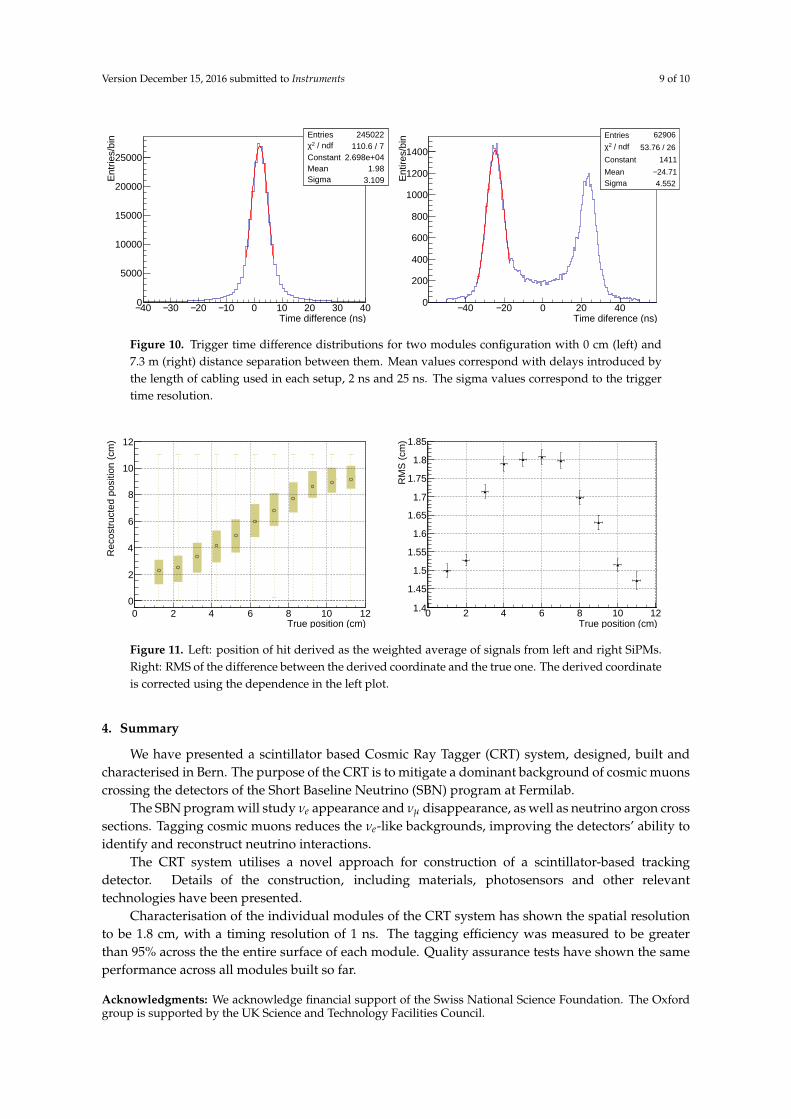
The difference in trigger times between two modules, in various configurations, was measuredusing crossing muons. Figure 10 shows results for the two modules triggering in coincidence; theleft shows results from an adjoining module configuration, and the right with a separation of 7.3 mbetween modules. The mean values of the trigger time differences correspond with delays introducedby the length of cabling used in each setup, 2 ns and 25 ns respectively.
Each scintillator strip is equipped with two WLS fibers and two SiPMs, one on each edge.This configuration enables the reconstruction of the position of a particle which hits the strip, by

Version December 15, 2016 submitted to Instruments 8 of 10
Entries 25499
Mean 99.77
RMS 1.279
Measured pulse delay (ns)95 96 97 98 99 100 101 102 103 104 105
Pul
ses
0
1000
2000
3000
4000
5000
6000
7000
8000Entries 25499
Mean 99.77
RMS 1.279
Figure 8. Accuracy of the FEB time stamp generator.
Signal amplitude (photoelectrons)
Trig
ger d
elay
w.r.
t. sc
intil
latio
n (n
s)
Signal amplitude (photoelectrons)
RM
S of
trig
ger a
rriva
l tim
e (n
s)
Figure 9. Arrival time (left) and its uncertainty (right) for the photons in CRT scintillator strips as afunction of signal amplitude at a threshold of 2.5 photoelectrons. The effective photon propagationdelay is 6.1±0.7 ns/m.
measuring the relative intensities registered by the SiPMs. Measurements were made with cosmicmuons entering normal to the plane at different transverse positions in the strip at 0.5 m from thereadout end. The muon’s true position was constrained with two scintillator counters working asa telescope in coincidence with the FEB of the module. Figure 11-left shows the reconstructed hitcoordinate versus its true position. Figure 11-right shows the RMS of the difference between thereconstructed and true coordinates as a function of the true coordinate.
Version December 15, 2016 submitted to Instruments 9 of 10
Entries 245022 / ndf 2χ 110.6 / 7
Constant 2.698e+04Mean 1.98Sigma 3.109
Time difference (ns)40− 30− 20− 10− 0 10 20 30 40
Ent
ries/
bin
0
5000
10000
15000
20000
25000
Entries 245022 / ndf 2χ 110.6 / 7
Constant 2.698e+04Mean 1.98Sigma 3.109
Entries 62906
/ ndf 2χ 53.76 / 26
Constant 1411
Mean 24.71− Sigma 4.552
Time diference (ns)40− 20− 0 20 40
Ent
ires/
bin
0
200
400
600
800
1000
1200
1400
Entries 62906
/ ndf 2χ 53.76 / 26
Constant 1411
Mean 24.71− Sigma 4.552
Figure 10. Trigger time difference distributions for two modules configuration with 0 cm (left) and7.3 m (right) distance separation between them. Mean values correspond with delays introduced bythe length of cabling used in each setup, 2 ns and 25 ns. The sigma values correspond to the triggertime resolution.
True position (cm)0 2 4 6 8 10 12
Rec
ostr
ucte
d po
sitio
n (c
m)
0
2
4
6
8
10
12
True position (cm)0 2 4 6 8 10 12
RM
S (
cm)
1.4
1.45
1.5
1.55
1.6
1.65
1.7
1.75
1.8
1.85
Figure 11. Left: position of hit derived as the weighted average of signals from left and right SiPMs.Right: RMS of the difference between the derived coordinate and the true one. The derived coordinateis corrected using the dependence in the left plot.
4. Summary
We have presented a scintillator based Cosmic Ray Tagger (CRT) system, designed, built andcharacterised in Bern. The purpose of the CRT is to mitigate a dominant background of cosmic muonscrossing the detectors of the Short Baseline Neutrino (SBN) program at Fermilab.
The SBN program will study νe appearance and νµ disappearance, as well as neutrino argon crosssections. Tagging cosmic muons reduces the νe-like backgrounds, improving the detectors’ ability toidentify and reconstruct neutrino interactions.
The CRT system utilises a novel approach for construction of a scintillator-based trackingdetector. Details of the construction, including materials, photosensors and other relevanttechnologies have been presented.
Characterisation of the individual modules of the CRT system has shown the spatial resolutionto be 1.8 cm, with a timing resolution of 1 ns. The tagging efficiency was measured to be greaterthan 95% across the the entire surface of each module. Quality assurance tests have shown the sameperformance across all modules built so far.
Acknowledgments: We acknowledge financial support of the Swiss National Science Foundation. The Oxfordgroup is supported by the UK Science and Technology Facilities Council.

Version December 15, 2016 submitted to Instruments 10 of 10
References
1. M. Antonello et al. [MicroBooNE and LAr1-ND and ICARUS-WA104 Collaborations], “A Proposal fora Three Detector Short-Baseline Neutrino Oscillation Program in the Fermilab Booster Neutrino Beam,”arXiv:1503.01520 [physics.ins-det].
2. A. Aguilar-Arevalo et al. [LSND Collaboration], “Evidence for neutrino oscillations from the observationof anti-neutrino(electron) appearance in a anti-neutrino(muon) beam,” Phys. Rev. D 64, 112007 (2001)doi:10.1103/PhysRevD.64.112007 [hep-ex/0104049].
3. A. A. Aguilar-Arevalo et al. [MiniBooNE Collaboration], “Improved Search for ν̄µ → ν̄e Oscillationsin the MiniBooNE Experiment,” Phys. Rev. Lett. 110, 161801 (2013) doi:10.1103/PhysRevLett.110.161801[arXiv:1303.2588 [hep-ex]].
4. K. Terao [MicroBooNE Collaboration], “MicroBooNE: Liquid Argon TPC at Fermilab,” JPS Conf. Proc. 8,023014 (2015). doi:10.7566/JPSCP.8.023014
5. N. McConkey [LAr1-ND Collaboration], “The LAr1-ND Experiment,” J. Phys. Conf. Ser. 650, no. 1, 012007(2015). doi:10.1088/1742-6596/650/1/012007
6. C. Montanari [ICARUS/WA104 Collaboration], “Icarus,” PoS NEUTEL 2015, 011 (2015).7. A. Surdo [ARGO-YBJ Collaboration], “Measurement of the Cosmic Ray spectra by the ARGO-YBJ
experiment,” Nucl. Part. Phys. Proc. 265-266, 255 (2015). doi:10.1016/j.nuclphysbps.2015.06.0668. Hamamatsu S12825-050P, http://www.hamamatsu.com/jp/en/S12571-050P.html9. M. Auger et al., JINST 11, no. 10, P10005 (2016) doi:10.1088/1748-0221/11/10/P10005 [arXiv:1606.02290
[physics.ins-det]].
c© 2016 by the authors. Submitted to Instruments for possible open access publicationunder the terms and conditions of the Creative Commons Attribution (CC-BY) license(http://creativecommons.org/licenses/by/4.0/).