a novel diode laser system for photodynamic therapy samsöe...
TRANSCRIPT
LUND UNIVERSITY
PO Box 117221 00 Lund+46 46-222 00 00
A novel diode laser system for photodynamic therapy
Samsöe Andersen, Eva; Petersen, PM; Andersen, PE; Andersson-Engels, Stefan; Svanberg,KatarinaPublished in:LASER-TISSUE INTERACTIONS, THERAPEUTIC APPLICATIONS, AND PHOTODYNAMIC THERAPY
DOI:10.1117/12.446515
2001
Link to publication
Citation for published version (APA):Samsöe Andersen, E., Petersen, PM., Andersen, PE., Andersson-Engels, S., & Svanberg, K. (2001). A noveldiode laser system for photodynamic therapy. In R. Birngruber, & H. van den Bergh (Eds.), LASER-TISSUEINTERACTIONS, THERAPEUTIC APPLICATIONS, AND PHOTODYNAMIC THERAPY (Vol. 4433, pp. 134-139). SPIE. https://doi.org/10.1117/12.446515
General rightsCopyright and moral rights for the publications made accessible in the public portal are retained by the authorsand/or other copyright owners and it is a condition of accessing publications that users recognise and abide by thelegal requirements associated with these rights.
• Users may download and print one copy of any publication from the public portal for the purpose of private studyor research. • You may not further distribute the material or use it for any profit-making activity or commercial gain • You may freely distribute the URL identifying the publication in the public portalTake down policyIf you believe that this document breaches copyright please contact us providing details, and we will removeaccess to the work immediately and investigate your claim.
A novel diode laser system for photodynamic therapy
Eva Sams�e� a, b, Paul M. Petersena, Peter E. Andersena,
Stefan Andersson-Engelsb and Katarina Svanbergb
aRis� National Laboratory, P.O Box 49, DK-4000 Roskilde, DenmarkbLund Institute of Technology, Lund University, Box 118, SE-221 00 Lund, Sweden
ABSTRACT
In this paper a novel diode laser system for photodynamic therapy is demonstrated. The system is based on linearspatial �ltering and optical phase conjugate feedback from a photorefractive BaTiO3 crystal. The spatial coherenceproperties of the diode laser are signi�cantly improved. The system provides an almost di�raction limited outputwhich is eÆciently coupled into a 50 �m core diameter �ber. The optical power transmitted through the �ber isincreased by a factor of six when the feedback is applied to the diode laser. 85 percent of the power from the freelyrunning laser diode is extracted in a high-quality beam and 80 percent of the output power is extracted through the�ber. The power transmitted through the �ber scales linearly with the power of the laser diode, which means that alaser diode emitting 1.7 W multi-mode radiation would provide 1 W of optical power through a 50 �m core diameter�ber. The system is compact, portable, stable, and easy to operate.
Keywords: Photodynamic therapy, Diode lasers, Medical optics instruments
1. INTRODUCTION
Photodynamic therapy (PDT) is a promising treatment modality of malignant and pre-malignant tumors.1{4 PDTrelies on the coexistence of three components: photosensitizer, light, and oxygen. The photosensitizer is administeredto the patient, where it accumulates selectively in the cancerous cells. When the light excites the photosensitive druga photochemical reaction occurs. This leads to the formation of singlet oxygen, which is a reactive and highlyaggressive molecule. The singlet oxygen reacts with its surroundings, i.e. the diseased tissue, causing selectivedestruction of the cancerous cells. Using the photosensitizer Æ-aminolevulinic acid (Æ-ALA) requires light with awavelength around 635 nm.
The use of diode laser systems in medicine has increased rapidly during the past decade since their compactness,low cost, and simple operation make them attractive in a clinical environment. They are continuously replacinglight sources previously used in PDT - large expensive systems that, in addition, are complex to operate.5 Aremaining drawback of presently available diode laser systems is that they provide a low-quality laser beam. Thismeans that they have poor coupling eÆciency to small-core diameter optical �bers and are only capable of deliveringthe treatment light through optical �bers with core diameters of 400 �m or more. This limitation is especiallyimportant to PDT. For this application it can be diÆcult to �nd a laser with suÆcient power through a thin �ber foroptimal treatment. The optimal �ber size in individual treatment cases is often less than 400 �m. When performinginterstitial PDT treatments, it is desirable to have a thin treatment �ber. Thus, there is a need for a new light sourcedelivering the therapeutic light through an optical �ber with a small core diameter.
Frequency selective (FS) phase conjugate feedback (PCF) has proven an eÆcient method for enhancement ofthe output from laser diodes.6,7 In this scheme a broad area laser (BAL) or a laser diode array (LDA) is exposedto external phase conjugate feedback8,9 from a self-pumped, photorefractive crystal.10,11 Furthermore, the systemincludes a spatial �lter and a frequency selective element (e.g. a Fabry-Perot etalon). The scheme forces the laserdiode to operate with high temporal coherence and to exhibit an almost di�raction limited output.
In this work, we investigate the spatial improvement and the temporal stability of a broad area laser implementedin a similar scheme. We observe a highly improved output from a 637 nm BAL. The quality of the beam is evaluatedby measuring the M2 beam quality factor, which is a measure of how well the beam can be focused.12 Approximately85 percent of the multi-mode power from the freely running BAL is extracted in an almost di�raction limited output.
� Contact E. Sams�e: e-mail: [email protected], Optics and Fluid Dynamics Department, Ris� National Laboratory,phone: (+45) 4677 4553.
Laser-Tissue Interactions, Therapeutic Applications, and Photodynamic Therapy,Reginald Birngruber, Hubert van den Bergh, Editors, Proceedings of SPIE Vol. 4433
(2001) © 2001 SPIE · 1605-7422/01/$15.00134
Downloaded from SPIE Digital Library on 04 Jul 2011 to 130.235.188.41. Terms of Use: http://spiedl.org/terms
x
y z L1L2
Modenumber m
SF
M
Output lobe
To opticalfiber
To externalfeedback
+�m
-�m
Externalfeedback
BAL
Far-fieldplane
Near-fieldplane
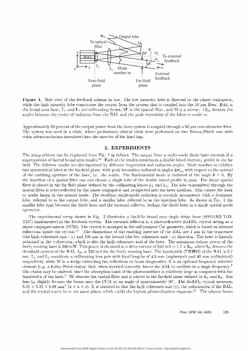
Figure 1. Side view of the feedback scheme in use. The low intensity lobe is directed to the phase conjugator,while the high intensity lobe constitutes the output from the system that is coupled into the 50 �m �ber. BAL isthe broad area laser, L1 and L2 are collimating lenses, SF is the spatial �lter, and M is a mirror. ��m denotes theangles between the center of radiation from the BAL and the peak intensities of the lobes in mode m.
Approximately 80 percent of the output power from the laser system is coupled through a 50 �m core-diameter �ber.The system was used in a clinic, where preliminary clinical trials were performed on two Wistar/Furth rats withcolon adenocarcinoma inoculated into the muscles of the hind legs.
2. EXPERIMENTS
The setup scheme can be explained from Fig. 1 as follows. The output from a multi-mode diode laser consists of asuperposition of lateral broad area modes.13 Each of the modes constitutes a double lobed intensity pro�le in the far�eld. The di�erent modes are distinguished by di�erent frequencies and radiation angles. Mode number m exhibitstwo symmetrical lobes in the far-�eld plane, with peak intensities radiated at angles ��m, with respect to the normalof the emitting aperture of the laser, i.e. the z-axis. The fundamental mode is radiated at the angle � = 0. Bythe insertion of a spatial �lter one can choose a single lobe of the double lobed pro�le to pass. The linear spatial�lter is placed in the far-�eld plane de�ned by the collimating lenses L1 and L2. The lobe transmitted through thespatial �lter is retro-re ected by the phase conjugator and re-injected into the laser medium. This causes the laserto prefer lasing in one spatial mode. The resulting single-mode radiation is strongly asymmetric with a dominantlobe, referred to as the output lobe, and a smaller lobe, referred to as the injection lobe. As shown in Fig. 1 thesmaller lobe runs between the diode laser and the external re ector, locking the diode laser in a single spatial modeoperation.
The experimental setup shown in Fig. 2 illustrates a GaAlAs broad area single-stripe laser (HPD1302-TO3-TEC) implemented in the feedback system. The external re ector is a photorefractive BaTiO3 crystal acting as aphase conjugate mirror (PCM). The crystal is arranged in the self-pumped Cat geometry, which is based on internalre ections inside the crystal.14 The dimensions of the emitting aperture of the BAL are 1 �m in the transverse(the high coherence axis - y) and 100 �m in the lateral (the low coherence axis - x) direction. The laser is linearlypolarized in the y-direction, which is also the high coherence axis of the laser. The maximum output power of thefreely running laser is 200 mW. This power is obtained at a drive current of 550 mA ' 1.7 � Ith, where Ith denotes thethreshold current of the BAL, Ith = 330 mA for the freely running laser. The bandwidth (FWHM) of the BAL is 0.7nm. L1 and L2 constitute a collimating lens pair with focal lengths of 4.5 mm (aspherical) and 40 mm (cylindrical)respectively, while W is a wedge extracting two re ections to beam diagnostics. E is an optional frequency selectiveelement (e.g. a Fabry-Perot etalon) that, when inserted correctly, forces the BAL to oscillate in a single frequency.7
The etalon may be omitted, since the absorption band of the photosensitizer is relatively large as compared with thebandwidth of the laser.4 SF denotes the spatial �lter and is placed in the far-�eld plane de�ned by L1 and L2. Thelens L3 slightly focuses the beam onto the PCM at an angle of approximately 50Æ. The BaTiO3 crystal measures5.41 � 5.35 � 6.98 mm3 (a � a � c). It is oriented so that the high coherence axis (y), the polarization of the BAL,and the crystal c-axis lie in the same plane, which yields the highest photorefractive response.15 The scheme forces
Proc. SPIE Vol. 4433 135
Downloaded from SPIE Digital Library on 04 Jul 2011 to 130.235.188.41. Terms of Use: http://spiedl.org/terms
SF
BaTiO3
L1 L3L2 W ME
xz
y
L6
L5
L4
Single mode fiber aligner
50 m fiber�
BAL
c
Far-fieldplane
To beam diagnostics
A
B
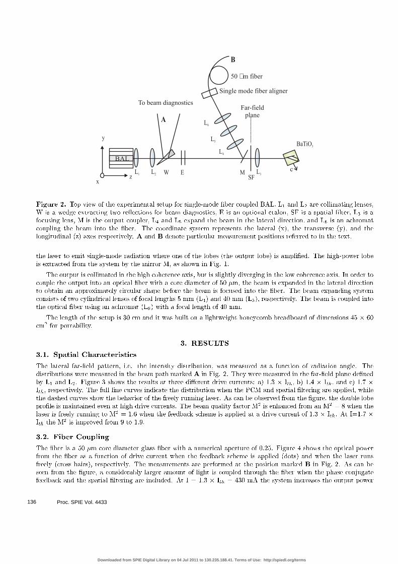
Figure 2. Top view of the experimental setup for single-mode �ber coupled BAL. L1 and L2 are collimating lenses,W is a wedge extracting two re ections for beam diagnostics, E is an optional etalon, SF is a spatial �lter, L3 is afocusing lens, M is the output coupler, L4 and L5 expand the beam in the lateral direction, and L6 is an achromatcoupling the beam into the �ber. The coordinate system represents the lateral (x), the transverse (y), and thelongitudinal (z) axes respectively. A and B denote particular measurement positions referred to in the text.
the laser to emit single-mode radiation where one of the lobes (the output lobe) is ampli�ed. The high-power lobeis extracted from the system by the mirror M, as shown in Fig. 1.
The output is collimated in the high coherence axis, but is slightly diverging in the low coherence axis. In order tocouple the output into an optical �ber with a core diameter of 50 �m, the beam is expanded in the lateral directionto obtain an approximately circular shape before the beam is focused into the �ber. The beam expanding systemconsists of two cylindrical lenses of focal lengths 5 mm (L4) and 40 mm (L5), respectively. The beam is coupled intothe optical �ber using an achromat (L6) with a focal length of 40 mm.
The length of the setup is 30 cm and it was built on a lightweight honeycomb breadboard of dimensions 45 � 60cm2 for portability.
3. RESULTS
3.1. Spatial Characteristics
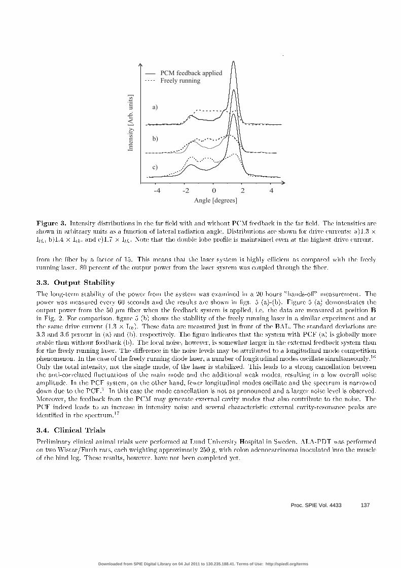
The lateral far-�eld pattern, i.e. the intensity distribution, was measured as a function of radiation angle. Thedistributions were measured in the beam path marked A in Fig. 2. They were measured in the far-�eld plane de�nedby L1 and L2. Figure 3 shows the results at three di�erent drive currents: a) 1.3 � Ith, b) 1.4 � Ith, and c) 1.7 �Ith, respectively. The full-line curves indicate the distribution when the PCM and spatial �ltering are applied, whilethe dashed curves show the behavior of the freely running laser. As can be observed from the �gure, the double lobepro�le is maintained even at high drive currents. The beam quality factor M2 is enhanced from an M2 = 8 when thelaser is freely running to M2 = 1.6 when the feedback scheme is applied at a drive current of 1.3 � Ith. At I=1.7 �Ith the M2 is improved from 9 to 1.9.
3.2. Fiber Coupling
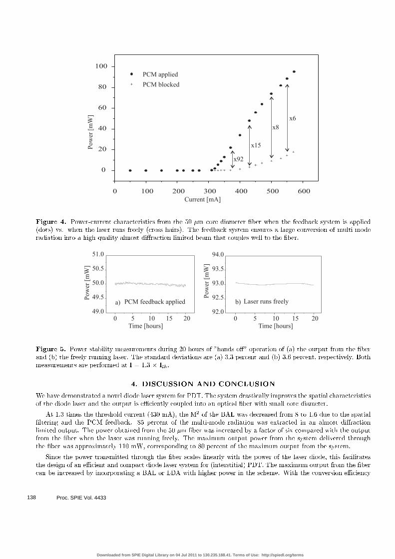
The �ber is a 50 �m core diameter glass �ber with a numerical aperture of 0.25. Figure 4 shows the optical powerfrom the �ber as a function of drive current when the feedback scheme is applied (dots) and when the laser runsfreely (cross hairs), respectively. The measurements are performed at the position marked B in Fig. 2. As can beseen from the �gure, a considerably larger amount of light is coupled through the �ber when the phase conjugatefeedback and the spatial �ltering are included. At I = 1.3 � Ith = 430 mA the system increases the output power
Proc. SPIE Vol. 4433136
Downloaded from SPIE Digital Library on 04 Jul 2011 to 130.235.188.41. Terms of Use: http://spiedl.org/terms
-4 -2 0 2 4
Inte
nsi
ty[A
rb.unit
s]
a)
b)
c)
Angle [degrees]
PCM feedback appliedFreely running
Figure 3. Intensity distributions in the far �eld with and without PCM feedback in the far �eld. The intensities areshown in arbitrary units as a function of lateral radiation angle. Distributions are shown for drive currents: a)1.3 �Ith, b)1.4 � Ith, and c)1.7 � Ith. Note that the double lobe pro�le is maintained even at the highest drive current.
from the �ber by a factor of 15. This means that the laser system is highly eÆcient as compared with the freelyrunning laser. 80 percent of the output power from the laser system was coupled through the �ber.
3.3. Output Stability
The long-term stability of the power from the system was examined in a 20 hours "hands-o�" measurement. Thepower was measured every 60 seconds and the results are shown in �gs. 5 (a)-(b). Figure 5 (a) demonstrates theoutput power from the 50 �m �ber when the feedback system is applied, i.e. the data are measured at position B
in Fig. 2. For comparison, �gure 5 (b) shows the stability of the freely running laser in a similar experiment and atthe same drive current (1.3 � Ith). These data are measured just in front of the BAL. The standard deviations are3.3 and 3.6 percent in (a) and (b), respectively. The �gure indicates that the system with PCF (a) is globally morestable than without feedback (b). The local noise, however, is somewhat larger in the external feedback system thanfor the freely running laser. The di�erence in the noise levels may be attributed to a longitudinal mode competitionphenomenon. In the case of the freely running diode laser, a number of longitudinal modes oscillate simultaneously.16
Only the total intensity, not the single mode, of the laser is stabilized. This leads to a strong cancellation betweenthe anti-correlated uctuations of the main mode and the additional weak modes, resulting in a low overall noiseamplitude. In the PCF system, on the other hand, fewer longitudinal modes oscillate and the spectrum is narroweddown due to the PCF.7 In this case the mode cancellation is not as pronounced and a larger noise level is observed.Moreover, the feedback from the PCM may generate external cavity modes that also contribute to the noise. ThePCF indeed leads to an increase in intensity noise and several characteristic external cavity-resonance peaks areidenti�ed in the spectrum.17
3.4. Clinical Trials
Preliminary clinical animal trials were performed at Lund University Hospital in Sweden. ALA-PDT was performedon two Wistar/Furth rats, each weighting approximatly 250 g, with colon adenocarcinoma inoculated into the muscleof the hind leg. These results, however, have not been completed yet.
Proc. SPIE Vol. 4433 137
Downloaded from SPIE Digital Library on 04 Jul 2011 to 130.235.188.41. Terms of Use: http://spiedl.org/terms
0 100 200 300 400 500 600
0
20
40
60
80
100
PCM applied
PCM blocked
Current [mA]
Pow
er[m
W]
x15
x8
x6
x92
Figure 4. Power-current characteristics from the 50 �m core diameter �ber when the feedback system is applied(dots) vs. when the laser runs freely (cross hairs). The feedback system ensures a large conversion of multi-moderadiation into a high-quality almost di�raction limited beam that couples well to the �ber.
0 5 10 15 2049.0
49.5
50.0
50.5
51.0
a) PCM feedback applied
Time [hours]
Pow
er[m
W]
0 5 10 15 2092.0
92.5
93.0
93.5
94.0
b) Laser runs freely
Time [hours]
Pow
er[m
W]
Figure 5. Power stability measurements during 20 hours of "hands-o�" operation of (a) the output from the �berand (b) the freely running laser. The standard deviations are (a) 3.3 percent and (b) 3.6 percent, respectively. Bothmeasurements are performed at I = 1.3 � Ith.
4. DISCUSSION AND CONCLUSION
We have demonstrated a novel diode laser system for PDT. The system drastically improves the spatial characteristicsof the diode laser and the output is eÆciently coupled into an optical �ber with small core diameter.
At 1.3 times the threshold current (430 mA), the M2 of the BAL was decreased from 8 to 1.6 due to the spatial�ltering and the PCM feedback. 85 percent of the multi-mode radiation was extracted in an almost di�ractionlimited output. The power obtained from the 50 �m �ber was increased by a factor of six compared with the outputfrom the �ber when the laser was running freely. The maximum output power from the system delivered throughthe �ber was approximately 110 mW, corresponding to 80 percent of the maximum output from the system.
Since the power transmitted through the �ber scales linearly with the power of the laser diode, this facilitatesthe design of an eÆcient and compact diode laser system for (interstitial) PDT. The maximum output from the �bercan be increased by incorporating a BAL or LDA with higher power in the scheme. With the conversion eÆciency
Proc. SPIE Vol. 4433138
Downloaded from SPIE Digital Library on 04 Jul 2011 to 130.235.188.41. Terms of Use: http://spiedl.org/terms
found in this study, a BAL/LDA emitting around 1.7 W multi-mode radiation would provide approximately 1 Wthrough the 50 �m �ber.
ACKNOWLEDGMENT
This work was supported by the Danish Technical Research Council grant number 9901433.
REFERENCES
1. T. J. Dougherty, \Photoradiation therapy for cutaneous and subscutaneous malignancies," J. Invest. Dermatol.77, p. 122, 1981.
2. D. Ash and S. B. Brown, \Photodynamic therapy - achievement and prospects," Br. J. Cancer 60, p. 151, 1989.
3. I. Wang, N. Bends�e, C. af Klinteberg, A. M. K. Enejder, S. Andersson-Engels, S. Svanberg, and K. Svanberg,\Photodynamic therapy vs. cryosurgery of basal cell carcinomas: results of a phase III clinical trial," Br. J.
Dermatol. 144, p. 832, 2001.
4. Q. Peng, T. Warloe, K. Berg, J. Moan, M. Kongshaug, K.-E. Giercksky, and J. M. Nesland, \5-aminolevulinicacid-based photodynamic therapy: clinical research and future challenges," Cancer 79, p. 2282, 1997.
5. I. Wang, Photodynamic Therapy and Laser-Based Diagnostic Studies of Malignant Tumours. PhD thesis, LundUniversity, 1999.
6. S. MacCormack and J. Feinberg, \High-brigthness output from a laser-diode array coupled to a phase-conjugating mirror," Opt. lett. 18, p. 211, 1993.
7. M. L�bel, P. M. Petersen, and P. M. Johansen, \Single-mode operation of a laser-diode array with frequency-selective phase-conjugate feedback," Opt. Lett. 23, p. 825, 1998.
8. B. Y. Zel'dovich, V. I. Popovichev, V. V. Ragul'skii, and F. S. Faizullo, \Connection between the wave frontsof the re ected and exciting light in stimulation mandel'shtam-brillouin scattering," Sov. Phys. JETP Lett. 15,p. 109, 1972.
9. A. Yariv and D. M. Pepper, \Ampli�ed re ection, phase conjugation and oscillation in degenerate four-wavemixing," Opt. lett. 1, p. 16, 1977.
10. A. Ashkin, G. D. Boyd, J. M. Dziedzic, R. G. Smith, A. A. Ballman, J. J. Levinstein, and K. Nassau, \Optically-induced refractive index inhomogeneities in LiNbO3 and LiTaO3," Appl. Phys. Lett. 9, p. 72, 1966.
11. J. Feinberg, D. Heiman, A. R. Tanguay, and R. Hellwarth, \Photorefractive e�ects and light-induced chargemigration in barium titanate," J. Appl. Phys. 51, p. 1297, 1980.
12. D. R. Hall and P. E. Jackson, The Physics and Technology of Laser Resonators, IOP Publishing Ltd, 1989.
13. J. M. Verdiell and R. Frey, \A broad-area mode-coupling model for multiple-stripe semiconductor lasers," IEEEJ. Quan. Elec. 26, p. 270, 1990.
14. J. Feinberg, \Self-pumped, continous wave phase conjugator using internal re ections," Opt. Lett. 7, p. 486,1982.
15. Y. Fainman, E. Klancnik, and S. H. Lee, \Optimal coherent image ampli�cation by two-wave coupling inphotorefractive BaTiO3," Opt. Eng. 25, p. 228, 1986.
16. X. Tang, J. P. van der Ziel, and A. K. Chin, \Characterisation of the array modes of high-power gain-guidedGaAs single-quantum-well laser arrays," IEEE J. Quan. Elec. 32, p. 1417, 1996.
17. M. L�bel, Improvement of the Coherence Characteristics of Laser Diode Arrays Using Photorefractive Phase
Conjugation. PhD thesis, Ris� National Laboratory, 1998.
Proc. SPIE Vol. 4433 139
Downloaded from SPIE Digital Library on 04 Jul 2011 to 130.235.188.41. Terms of Use: http://spiedl.org/terms