a novel flux-space-vector-based direct … · control scheme for pmsg used in variable-speed...
TRANSCRIPT

DOI: 10.23883/IJRTER.2017.3427.YJKTR 37
A NOVEL FLUX-SPACE-VECTOR-BASED DIRECT TORQUE
CONTROL SCHEME FOR PMSG USED IN VARIABLE-SPEED
DIRECT-DRIVE WECS
B.VENKATESWARARAJU1, B. YELLA REDDY2 1Mtech Scholar, 2Assistant Professor
Department of Electrical and Electronics Engineering
NEWTON’S INSTITUTE OF ENGINEERING, Allugurajupally, Koppunoor, Macherla, Guntur-522426
Abstract: This paper proposes a novel flux-space-vector-based direct torque control (DTC) scheme for
permanent-magnet synchronous generators (PMSGs) used in variable-speed direct-drive wind energy
conversion systems (WECSs). The discrete-time control law, which is derived from the perspective of
flux space vectors and load angle, predicts the desired stator flux vector for the next time-step with the
torque and stator flux information only. The space vector modulation (SVM) is then employed to
generate the reference voltage vector, leading to a fixed switching frequency, as well as lower flux and
torque ripples, when compared to the conventional DTC. Compared with other SVM-based DTC
methods in the literature, the proposed DTC scheme eliminates the use of proportional–integral
regulators and is less dependent on machine parameters, e.g., stator inductances and permanent-magnet
flux linkage, while the main advantages of the DTC, e.g., fast dynamic response and no need of
coordinate transform, are preserved. The proposed DTC scheme is applicable for both non salient-pole
and salient-pole PMSGs. The overall control scheme is simple to implement and is robust to parameter
uncertainties and variations of the PMSGs. The effectiveness of the proposed discrete-time DTC scheme
is verified by simulation and experimental results on a 180-W salient-pole PMSG and a 2.4-kW non
salient-pole PMSG used in variable-speed direct-drive WECSs.
Keywords: Direct Torque Control (DTC), WECSs, SVM, PMSG. DTC, WECSs, SVM, PMSG.
I. INTRODUCTION
Over the last two decades, the increasing concerns on energy crisis and environmental pollutions have
significantly promoted the utilization of renewable energy. Among various renewable energy sources,
wind energy has become one of the most cost-effective sources for electricity generation. The variable-
speed wind energy conversion systems (WECSs), which can be operated in the maximum power point
tracking (MPPT) mode, have attracted considerable interests, owing to their high energy production
efficiency and low torque spikes . Among different types of generators, the permanent-magnet
synchronous generators (PMSGs) have been found superior, owing to their advantages such as high
power density, high efficiency, and high reliability. Furthermore, a PMSG with a high number of poles
can be connected directly to a wind turbine without the use of a gearbox, which significantly reduces the
construction, operation, and maintenance costs of the WECSs. Typically, the control systems of PMSGs
adopt a decoupled current control executed in a synchronized rotating reference frame. In the last few
decades, an alternative electric machine control scheme called the direct torque control (DTC) has
attracted extensive attention from both academia and industry. Different from the decoupled current
control, the DTC directly controls electromagnetic torque and stator flux linkage instead of armature
currents, hence possessing the merits of fast dynamic response, simple implementation, and high
International Journal of Recent Trends in Engineering & Research (IJRTER) Volume 03, Issue 09; September - 2017 [ISSN: 2455-1457]
@IJRTER-2017, All Rights Reserved 38
robustness to external disturbances. The DTC has been applied successfully in high-performance
industrial servo drive systems. For WECS applications, the DTC may facilitate the realization of MPPT
with the optimal torque control , since the optimal torque command can be applied directly in the DTC
without the need of wind speed measurements. In this way, the outer loop speed or power controller,
which is necessary in the decoupled current control, can be eliminated. In the conventional DTC, the
voltage vector commands are determined primarily by the outputs of two hysteresis comparators. Once
selected, the desired voltage vector will remain unchanged until the hysteresis states are updated.
Although this voltage modulation scheme is simple to execute, it will lead to irregular and unpredictable
torque and flux ripples, particularly when the DTC is applied on a digital platform. To solve these
problems, many approaches have been developed from different perspectives. One natural thought is to
increase the number of available voltage vectors, e.g., using multilevel converters, or equally dividing
the sampling period into multiple intervals. However, these methods will increase the hardware cost,
need additional prediction for rotor speed, or have a limited ripple reduction improvement. Another
effective technique is to integrate the space vector modulation (SVM) algorithm into the DTC. The
SVM is able to convert the input voltages into gate signals for the inverter using a fixed switching
frequency A variety of SVM-based DTC schemes have been investigated for permanent-magnet
synchronous machines (PMSMs) in the last few decades. In general, they can be classified into two
categories based on how the voltage references are generated in the stationary reference frame. In the
first category, the decoupled voltage references in the synchronously rotating reference frame are
acquired and then transformed to the stationary reference frame using the rotary coordinate
transformation. In the second category, the voltage references are obtained directly from the incremental
stator flux vectors in the stationary reference frame without coordinate transformation. Both methods
can reduce torque and flux ripples, but need proportional–integral (PI) controllers to regulate the torque
and stator flux errors. The PI gains are usually tuned by a trial-and-error procedure. Poorly tuned PI
gains will deteriorate the dynamic performance of the DTC. In addition, according to, a real DTC
scheme should not contain PI regulators. More recently, a predictive current control and a deadbeat
direct torque and flux control were investigated for surface-mounted and interior PMSMs. These control
schemes provide good dynamic performance, provided that the information of some machine
parameters, e.g., stator inductances and permanent-magnet flux linkage, is accurate. Therefore, the
performance of the control systems would be more or less influenced by the variations of the machine
parameters. Moreover, these control schemes are based on the inverse machine model or a graphical
method, which increase the computational complexity.
II. DIRECT-DRIVE PMSG-BASED WECSS
The configuration of a direct-drive PMSG-based WECS is shown in Fig1, where the wind turbine is
connected to the PMSG directly without a gearbox. The electrical power enerated by the PMSG is
transmitted to a power grid or supplied to a load via a variable-frequency power converter. Typically,
the power electronic conversion system consists of a machine-side converter (MSC) and a grid-side
converter (GSC) connected back-to-back via a dc link. This paper considers the standard power
converter topology in a PMSG-based WECS, where both the MSC and the GSC are two-level fully
controlled voltage source converters.

International Journal of Recent Trends in Engineering & Research (IJRTER) Volume 03, Issue 09; September - 2017 [ISSN: 2455-1457]
@IJRTER-2017, All Rights Reserved 39
Fig1. Configuration of a direct-drive PMSG-based WECS connected to a power grid/load.
A. Wind Turbine Aerodynamic & Shaft Dynamic Models
The mechanical power that can be extracted from wind by a wind turbine is given by
(1) Where ρ is the air density; Ar is the area swept by the blades; vω is the wind speed; CP is the turbine
power coefficient; ωt is the turbine shaft speed; and λ is the tip-speed ratio, which is defined by
where r is the radius of the wind turbine rotor plane.
Fig2. Space vector diagram of the fluxes and currents of PMSGs.
As the wind turbine is connected to the PMSG directly, the shaft system of the WECS can be
represented by a one-mass model. The motion equation is then given by
where 2H is the total inertia constant of the WECS, Pe is the electric power generated by the PMSG, and
D is the damping coefficient.
International Journal of Recent Trends in Engineering & Research (IJRTER) Volume 03, Issue 09; September - 2017 [ISSN: 2455-1457]
@IJRTER-2017, All Rights Reserved 40
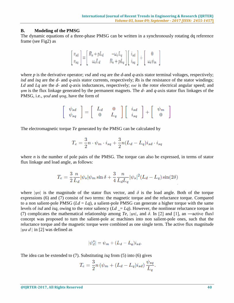
B. Modeling of the PMSG
The dynamic equations of a three-phase PMSG can be written in a synchronously rotating dq reference
frame (see Fig2) as
where p is the derivative operator; vsd and vsq are the d-and q-axis stator terminal voltages, respectively;
isd and isq are the d- and q-axis stator currents, respectively; Rs is the resistance of the stator windings;
Ld and Lq are the d- and q-axis inductances, respectively; ωe is the rotor electrical angular speed; and
ψm is the flux linkage generated by the permanent magnets. The d- and q-axis stator flux linkages of the
PMSG, i.e., ψsd and ψsq, have the form of
The electromagnetic torque Te generated by the PMSG can be calculated by
where n is the number of pole pairs of the PMSG. The torque can also be expressed, in terms of stator
flux linkage and load angle, as follows:
where |ψs| is the magnitude of the stator flux vector, and δ is the load angle. Both of the torque
expressions (6) and (7) consist of two terms: the magnetic torque and the reluctance torque. Compared
to a non salient-pole PMSG (Ld = Lq), a salient-pole PMSG can generate a higher torque with the same
levels of isd and isq, owing to the rotor saliency (Ld _= Lq). However, the nonlinear reluctance torque in
(7) complicates the mathematical relationship among Te, |ψs|, and δ. In [2] and [1], an ―active flux‖
concept was proposed to turn the salient-pole ac machines into non salient-pole ones, such that the
reluctance torque and the magnetic torque were combined as one single term. The active flux magnitude
|ψa d | in [2] was defined as
The idea can be extended to (7). Substituting isq from (5) into (6) gives

International Journal of Recent Trends in Engineering & Research (IJRTER) Volume 03, Issue 09; September - 2017 [ISSN: 2455-1457]
@IJRTER-2017, All Rights Reserved 41
Since ψsq = |ψs| · sin δ, the torque in terms of the stator flux magnitude, active flux magnitude, and load
angle can be expressed as
Dividing (7) by (10), the active flux magnitude in terms of |ψs| and δ has the form of
The active flux vector ψa d , which is aligned on the d-axis, can be obtained by
Fig3. Schematic of the proposed DTC for a direct-drive PMSG-based WECS.
Fig4. Discrete-time programmable LPF-based stator flux estimator.
where ψsαβ and isαβ are the stator flux and current vectors in the stationary reference frame,
respectively. The diagram in Fig4 illustrates the relationship between the fluxes and currents of the
PMSG in the vector space, where ψmαβ is the rotor flux vector in the stationary reference frame.
III. PROPOSED DISCRETE-TIME DTC
In the proposed DTC, all the calculations are executed in the stationary αβ reference frame. The
schematic diagram of the proposed DTC is shown in Fig. 3. A reference flux vector estimator (RFVE) is
designed to calculate the desired stator flux vector ψ∗ sαβ using the estimated and reference values of
the stator flux and electromagnetic torque without PI regulators. In this paper, the stator flux linkages are
estimated by the programmable low-pass filter (LPF) introduced in [19]. To effectively eliminate the dc

International Journal of Recent Trends in Engineering & Research (IJRTER) Volume 03, Issue 09; September - 2017 [ISSN: 2455-1457]
@IJRTER-2017, All Rights Reserved 42
drift over a wide speed range, the cutoff frequency of the LPF, i.e., ωc, is adjusted according to the rotor
electrical speed ωe by ωc = k · ωe, where k is a constant. The schematic of the discrete-time
programmable LPF-based stator flux estimator is shown in Fig. 4. The time derivative term is
approximated by the Euler backward differentiation, which is given as
where Ts is the sampling period, which is the same as the switching period and control cycle in the
proposed DTC. The compensating gain gc and phase angle θc for the output of the LPF are defined as
follows:
The electromagnetic torque can be calculated as
Compared to (7), the torque expression in (10) is greatly simplified mathematically and can be written as
a function of three time-variant variables |ψs|, |ψa d |, and δ. Taking the derivative of (10) on both sides
with respect to time yields
The discrete-time form of (17) for a short time interval is given as
where |ψs0|, |ψa d0 |, and δ0 are the stator flux magnitude, active flux amplitude, and load angle at the
reference point, respectively. Equation (18) demonstrates that the flux linkages |ψs0| and |ψa d0 | and
the loading condition (related to δ0 and |ψa d0 |) will affect the weights of the flux and load angle
increments in the torque increment calculation. In the kth control step, |ψs0| = |ψs[k]|, |ψa d0 | = |ψa d
[k]|, and δ0 = δ[k]. Then, (18) in the discrete-time domain can be written as
The torque Te[k] has the form of
International Journal of Recent Trends in Engineering & Research (IJRTER) Volume 03, Issue 09; September - 2017 [ISSN: 2455-1457]
@IJRTER-2017, All Rights Reserved 43
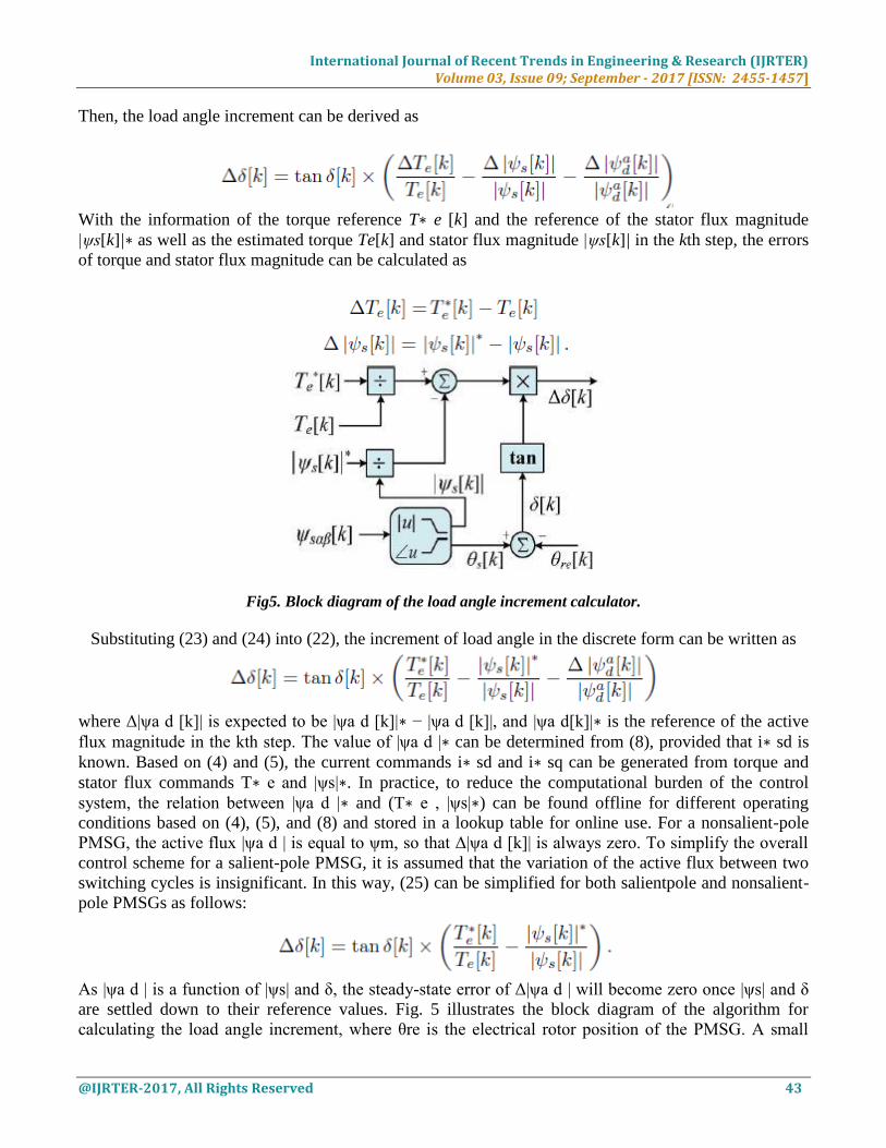
Then, the load angle increment can be derived as
With the information of the torque reference T∗ e [k] and the reference of the stator flux magnitude
|ψs[k]|∗ as well as the estimated torque Te[k] and stator flux magnitude |ψs[k]| in the kth step, the errors
of torque and stator flux magnitude can be calculated as
Fig5. Block diagram of the load angle increment calculator.
Substituting (23) and (24) into (22), the increment of load angle in the discrete form can be written as
where Δ|ψa d [k]| is expected to be |ψa d [k]|∗ − |ψa d [k]|, and |ψa d[k]|∗ is the reference of the active
flux magnitude in the kth step. The value of |ψa d |∗ can be determined from (8), provided that i∗ sd is
known. Based on (4) and (5), the current commands i∗ sd and i∗ sq can be generated from torque and
stator flux commands T∗ e and |ψs|∗. In practice, to reduce the computational burden of the control
system, the relation between |ψa d |∗ and (T∗ e , |ψs|∗) can be found offline for different operating
conditions based on (4), (5), and (8) and stored in a lookup table for online use. For a nonsalient-pole
PMSG, the active flux |ψa d | is equal to ψm, so that Δ|ψa d [k]| is always zero. To simplify the overall
control scheme for a salient-pole PMSG, it is assumed that the variation of the active flux between two
switching cycles is insignificant. In this way, (25) can be simplified for both salientpole and nonsalient-
pole PMSGs as follows:
As |ψa d | is a function of |ψs| and δ, the steady-state error of Δ|ψa d | will become zero once |ψs| and δ
are settled down to their reference values. Fig. 5 illustrates the block diagram of the algorithm for
calculating the load angle increment, where θre is the electrical rotor position of the PMSG. A small

International Journal of Recent Trends in Engineering & Research (IJRTER) Volume 03, Issue 09; September - 2017 [ISSN: 2455-1457]
@IJRTER-2017, All Rights Reserved 44
dead band should be set up for Te[k] and |ψs[k]| to avoid a zero denominator. The reference stator flux
angle θ∗ s[k] can then be obtained from the following equation:
The effect of the rotor speed is taken into consideration, by adding the term ωe[k]Ts to compensate the
rotor position increment when the PMSG operates at a high speed. According to (27) and the magnitude
of the desired stator flux linkage |ψs[k]|∗, the reference stator flux vector in the stationary reference
frame, i.e., ψ∗ sαβ[k], can be expressed as ψ∗ sαβ[k] = |ψs[k]|∗ · ejθ∗s [k]. Then, the voltage space
vector u sαβ[k] neglecting the voltage drop on the stator resistance can be acquired, as shown in Fig. 6.
Considering the effect of stator resistance, the expression of the desired stator voltage vector in a
discrete-time form can be written as
When implementing the proposed discrete-time DTC, the criterion dTe/dδ > 0 should be always met to
ensure the stability of the direct-torque-controlled PMSG systems.
Fig6. Voltage vector neglecting the stator resistance in the space vector analysis.
According to this stability criterion, the maximum load angle for a salient-pole PMSG is
The derivation of (25) is provided in the Appendix. With the knowledge of usαβ[k], proper switching
signals can be generated by the SVM module to achieve fast and accurate torque and flux linkage
control.

International Journal of Recent Trends in Engineering & Research (IJRTER) Volume 03, Issue 09; September - 2017 [ISSN: 2455-1457]
@IJRTER-2017, All Rights Reserved 45
IV. SIMULATION RESULT
Fig17. Closed Loop Control System of Three Phase Converters.
Fig18. Simulation model of pmsg based wind energy conversion system.

International Journal of Recent Trends in Engineering & Research (IJRTER) Volume 03, Issue 09; September - 2017 [ISSN: 2455-1457]
@IJRTER-2017, All Rights Reserved 46
Fig19. Active Power of Three Phase Inverter And Batteries, Active Power And Load Demand At Different
Dynamic Loads.
Fig20. Simulation Results of Wind Speed, Load Voltage, Frequency.

International Journal of Recent Trends in Engineering & Research (IJRTER) Volume 03, Issue 09; September - 2017 [ISSN: 2455-1457]
@IJRTER-2017, All Rights Reserved 47
Fig21. Simulation results of fuel cell currents and voltages
V. CONCLUSION
This paper has proposed a novel discrete-time DTC based on flux space vectors for PMSGs used in
direct-drive WECSs. The algorithm is easy to implement and is suitable for digital control systems using
relatively low sampling frequencies. The torque and flux ripples have been significantly reduced with
the integration of the SVM. In addition, the overall DTC scheme eliminated the use of PI controllers,
showed strong robustness to machine parameter variations, and achieved fast dynamic responses. The
proposed DTC scheme can be applied to both non salient-pole and salient-pole PMSGs. Simulation and
experimental results have been carried out to validate the effectiveness of the proposed DTC scheme on
a 180-W salient pole PMSG and a non salient-pole PMSG used in a 2.4-kW Sky stream 3.7 direct-drive
WECS. According to (7), the derivative of electromagnetic torque with respect to load angle can be
derived as
For the non salient-pole PMSGs (Ld = Lq), the stable operating region of δ is within (−π/2, π/2). If Ld
_= Lq, (A-1) can be simplified as
where a and b are both positive coefficients. The solution to (A-2) can be derived as

International Journal of Recent Trends in Engineering & Research (IJRTER) Volume 03, Issue 09; September - 2017 [ISSN: 2455-1457]
@IJRTER-2017, All Rights Reserved 48
Therefore, the maximum load angle for a salient-pole PMSG is
√Equation (A-4) indicates that δmax exceeds π/2 since (b − √b2 + 8a2)/(4a) < 0. On the other hand, the
inequality (b + b2 + 8a2)/(4a) > 1 should be satisfied, in order for the PMSG to be operated stably
within [−δmax, δmax]. Solving the inequality yields
REFERENCES I. Y. Zhao, C.Wei, Z. Zhang, andW. Qiao, ―A review on position/speed sensor less control for permanent-magnet
synchronous machine-based wind energy conversion systems,‖ IEEE J. Emerging Sel. Topics Power Electron., vol.
1, no. 4, pp. 203–216, Dec. 2013.
II. W. Qiao, L. Qu, and R. G. Harley, ―Control of IPM synchronous generator for maximum wind power generation
considering magnetic saturation,‖ IEEE Trans. Ind. Appl., vol. 45, no. 3, pp. 1095–1105, May/Jun. 2009.
III. W. Qiao, X. Yang, and X. Gong, ―Wind speed and rotor position sensor less control for direct-drive PMG wind
turbines,‖ IEEE Trans. Ind. Appl., vol. 48, no. 1, pp. 3–11, Jan./Feb. 2012.
IV. Direct Torque Control—The World’s Most Advanced AC Drive Technology, Tech. Guide No. 1, ABB, Zürich,
Switzerland, Jun. 2011.
V. Z. Zhang, Y. Zhao, W. Qiao, and L. Qu, ―A space-vector modulated sensor less direct-torque control for direct-
drive PMSG wind turbines,‖ IEEE Trans. Ind. Appl., vol. 50, no. 4, pp. 2331–2341, Jul./Aug. 2014.
VI. L. Zhong, M. F. Rahman, W. Y. Hu, and K. W. Lim, ―Analysis of direct torque control in permanent magnet
synchronous motor drives,‖ IEEE Trans. Power Electron., vol. 12, no. 3, pp. 528–536, May 1997.
VII. C. A. Martins, X. Roboam, T. A. Meynard, and A. S. Carvalho, ―Switching frequency imposition and ripple
reduction in DTC drives by using a multilevel converter,‖ IEEE Trans. Power Electron., vol. 17, no. 2, pp. 286–297,
Mar. 2002.
VIII. Y. Zhang, J. Zhu, Z. Zhao, W. Xu, and D. G. Dorrell, ―An improved direct torque control for three-level inverter-
fed induction motor sensorless drive,‖ IEEE Trans. Power Electron., vol. 27, no. 3, pp. 1502–1513, Mar. 2002.
IX. D. Casadei, F. Profumo, and G. Serra, ―FOC and DTC: Two viable schemes for induction motors torque control,‖
IEEE Trans. Power Electron., vol. 17, no. 5, pp. 779–787, Sep. 2002.
X. G. S. Buja and M. P. Kazmierkowski, ―Direct torque control of PWM inverter-fed AD motors—A survey,‖ IEEE
Trans. Ind. Electron., vol. 42, no. 4, pp. 344–350, Aug. 1995.