a novel gps survey antenna - gps & gnss equipment ... · a novel gps survey antenna waldemar...
TRANSCRIPT
A Novel GPS Survey Antenna
Waldemar Kunysz, NovAtel Inc.
BIOGRAPHY Waldemar Kunysz obtained a BSEE from the Technical University of Nova Scotia in 1989. From 1991 to 1995 he worked on phased array antennas for Microwave Landing Systems with Micronav Inc. From 1995 to the present he has been with NovAtel Inc. He has published several technical papers and proceedings articles for various conferences. His current research interests include antenna theory and design, multipath mitigation techniques, genetic algorithms and electromagnetic compatibility. ABSTRACT A novel GPS antenna for surveying applications is proposed. It is a fixed beam phased array of aperture-coupled slots optimized to receive a right hand polarized signal. The proposed antenna is made out of a single PCB board. Another PCB board is placed underneath the antenna to act as a reflector in order to reinforce the antenna directivity and reduce the back-lobe radiation. The radiation pattern roll-off of this antenna is sharper than the conventional GPS patch antennas mounted in the “choke ring” configuration. The sharp pattern roll-off allows reducing the antenna’s susceptibility to multipath generated replicas of the GPS signal. The antenna is much smaller and lighter than a corresponding typical “choke ring” antenna. There is no phase center offset between the L1 and L2 GPS frequencies and the antenna does not require any alignment with respect to a given direction (such as North) due to its natural symmetry. Due to its planar structure it can be easily buried in the vehicle or aircraft skin.
INTRODUCTION GPS antenna requirements differ in various applications. For precise surveying applications, ideally the antenna should receive only signals above the horizon and reject all signals below the horizon plane of the antenna, have a known and stable phase center that is co-located with the geometrical center of the antenna, and have perfect circular polarization characteristics to maximize the reception of the incoming right hand polarized (RHP) signal. A typical measure of merit of antenna polarization characteristics is Axial Ratio (AR). For dual frequency operation (L1 and L2), the antenna should also have a common phase center at both frequencies and ideally the same radiation pattern and axial ratio characteristics. There is, of course, no antenna that could meet all these requirements. The closest antenna that meets most of these requirements, to some degree, is a patch antenna mounted on a choke ring ground plane. Such an antenna is, however, large, bulky, heavy and relatively expensive, prohibiting its use in various applications. The new antenna presented in this paper is light and small and does not require a choke ring ground plane to achieve performance similar or better to a patch antenna in the choke ring ground plane configuration. CHOKE RING GROUND PLANE ANTENNA In order to see the benefit of the new antenna, we need to understand what type of performance is achieved with a patch antenna mounted in the choke ring ground plane configuration. We will use the following figures of merit: Axial Ratio, antenna amplitude directivity pattern roll-off (elevation plane), antenna amplitude directivity pattern
variation in azimuth plane, phase center location and phase center variation. Choke ring ground planes are a circular shaped ground plane with quarter wavelength slots that are shorted at the bottom and open at the top. This translates to a very high impedance ground plane that does not support image currents generated within the ground plane that normally would interfere with the currents generated within the patch antenna itself. This feature translates to very low side-lobes underneath the antenna horizon and very smooth amplitude and phase patterns generated by the antenna. In addition, very good Axial Ratio values (less than 3 dB) above 10 deg. elevation angle are achieved. The large size of the ground plane, on the other hand, translates to sharper amplitude roll-off (from zenith to the horizon) and increased main beam directivity of the antenna. Typical roll-off is in order of 10 to 12 dBi from zenith (90° elevation angle) to horizon (0° elevation angle) as compared to 3-5 dB roll-off of the patch antenna itself. Typical increase in the main beam directivity is in order of 1-2 dBi as compared to a stand-alone patch antenna without the choke ring ground plane. This performance enhancement is paid for with the size and weight of the additional ground plane. Typical diameter size of the choke ring is in the order of 14” to 16” and a weight of 10-20 lbs. In dual frequency operation, the phase center offset is inherited from the patch antenna itself. Since patch antennas use a stack configuration in order to resonate at two frequencies, they have a natural vertical offset between L1 and L2 phase centers that cannot be compensated for with a choke ring ground plane. Good surveying antennas currently available on the market have a typical L1-L2 offset in the order of 5-20mm. For high-end applications such as tectonic movement monitoring this offset must be corrected for, especially for very long GPS baseline measurements. Microstrip patch antennas with stable phase centers must be fed in at least two points, preferable in four points (for all four edges of rectangular/square patch). Since the antenna must be circularly polarized, a 90° phase gradient must be established between the feeding points. The feed network to establish a 90° phase gradient for a two point feed system is relatively simple (90° hybrid will do), however as the number of feeds is increased the feed network becomes more complex and lossy. NEW ANTENNA CONCEPT The new, patent pending, antenna is not a patch antenna but an array of multiple spiral slots that are electromagnetically coupled to a feeding network. Let’s refer to it as an aperture coupled slot array antenna and
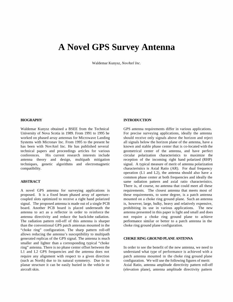
denote it as a pinwheel type antenna, due to its internal layout nature. See Figure 1 for a board layout of a 4-arm spiral pinwheel antenna.
Figure 1. PCB layout for four-arm spiral L1 antenna The actual antenna developed for production has 12 arms. The spatial difference between each two consecutive spiral arms is 30°, as well the electrical phase length of the feeding network is set to 30°. This arrangement allows having a more stable phase center (12 feeding points versus 4) and achieving excellent circular polarization. The feeding network is a leaky wave microstrip circuit in order to avoid complexity, keep it simple and maintain uniform amplitude excitation for all slots. The pinwheel antenna is designed to operate at two L1 and L2 bands of GPS and Glonass navigation systems. Six spiral arms resonate at L1 band and the other six arms resonate at L2 band. L1 and L2 spiral arms are interleaved to maintain a natural symmetry of the antenna in all three axes: x, y and z. The pinwheel antenna is made out of a flat printed circuit board (PCB), with the upper layer being the ground plane layer. Having the ground plane as the top layer provides an additional shielding against electromagnetic pulses generated by lightning or human related activities. In addition, the electric field is forced to zero (boundary condition) for the signals tangential to the ground plane (antenna horizon). This feature translates to a sharp amplitude pattern roll-off near horizon, available only with choke ring ground plane or with extremely large ground planes (diameter in excess of 18-20”). The typical amplitude roll-off is 12 dB at L1 band and 15 dB at L2 band. This performance is achieved with a diameter of only 6.25”. In addition, the antenna is very light (500 grams) which make this antenna easily adaptable to any surveying applications.
There is no phase center offset between L1 and L2 bands for all three axes (x, y and z), due to the following features of this antenna:
1. Natural symmetry of all slots with respect to geometrical center of antenna.
2. L1 and L2 slots are interleaved to maintain symmetry between both bands.
3. All L1 and L2 slots are contained in the same z-axis plane, since no vertical offset in physical layout exists between the slots.
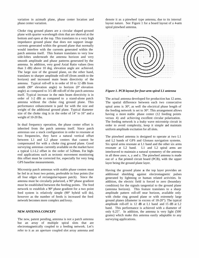
To maintain a good front/back ratio a thin metal reflector is placed underneath the antenna board. This prevents the multipath generated replicas of GPS or Glonass signals to be amplified by the antenna. In the current configuration the ground plane of the Low Noise Amplifier (LNA) is used as an antenna’s reflector. ANECHOIC CHAMBER MEASUREMENTS The antenna performance was validated by performing detailed anechoic chamber measurements and various GPS live signal tests. The main purpose of the anechoic chamber measurements was to determine the phase center location, its stability and amplitude radiation patterns. The horizontal phase center variation from the geometrical phase center of the antenna is shown on the next two graphs.
Figure 2. L1 Channel phase center variation in
horizontal plane for 12-arm L1/L2 antenna (GPS-600)
One shall keep in mind that antenna boresight angle 0° corresponds to a GPS elevation angle of 90° and vice-
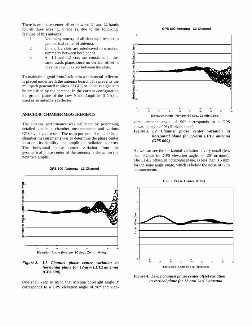
versa antenna angle of 90° corresponds to a GPS elevation angle of 0° (Horizon plane). Figure 3. L2 Channel phase center variation in
horizontal plane for 12-arm L1/L2 antenna (GPS-600)
As we can see the horizontal variation is very small (less than 0.2mm for GPS elevation angles of 20° or more). The L1-L2 offset, in horizontal plane, is less than 0.5 mm for the same angle range, which is below the noise of GPS measurements.
Figure 4. L1-L2 channel phase center offset variation in vertical plane for 12-arm L1/L2 antenna
G P S - 6 0 0 A n t e n n a - L 1 C h a n n e l
-2
-1.5
-1
-0.5
0
0.5
1
1.5
2
0 10 20 30 40 50 60 70 80 90
E l e v a t i o n A n g l e ( H o r i z on = 9 0 d e g . , Z e n i t h = 0 d e g . )
Ho
rizo
nta
l Ph
ase
Cen
ter
Dev
iati
on
(m
m)
G P S - 6 0 0 A n t e n n a - L 2 C h a n n e l
-2
-1.5
-1
-0.5
0
0.5
1
1.5
2
0 10 20 30 40 50 60 70 80 90
E l e v a t i o n A n g l e ( H o r i z on = 9 0 d e g . , Z e n i t h = 0 d e g . )
Ho
rizo
nta
l P
has
e C
ente
r D
evia
tio
n (
mm
)
L 1 - L 2 P h a s e C e n t e r O f f s e t
-5
-4
-3
-2
-1
0
1
2
3
4
5
0 10 20 30 40 50 60 70 80 90
E l e v a t i o n A n g l e (9 0 d e g - H o r i z o n)
Z a
xis
Off
set (
mm
)
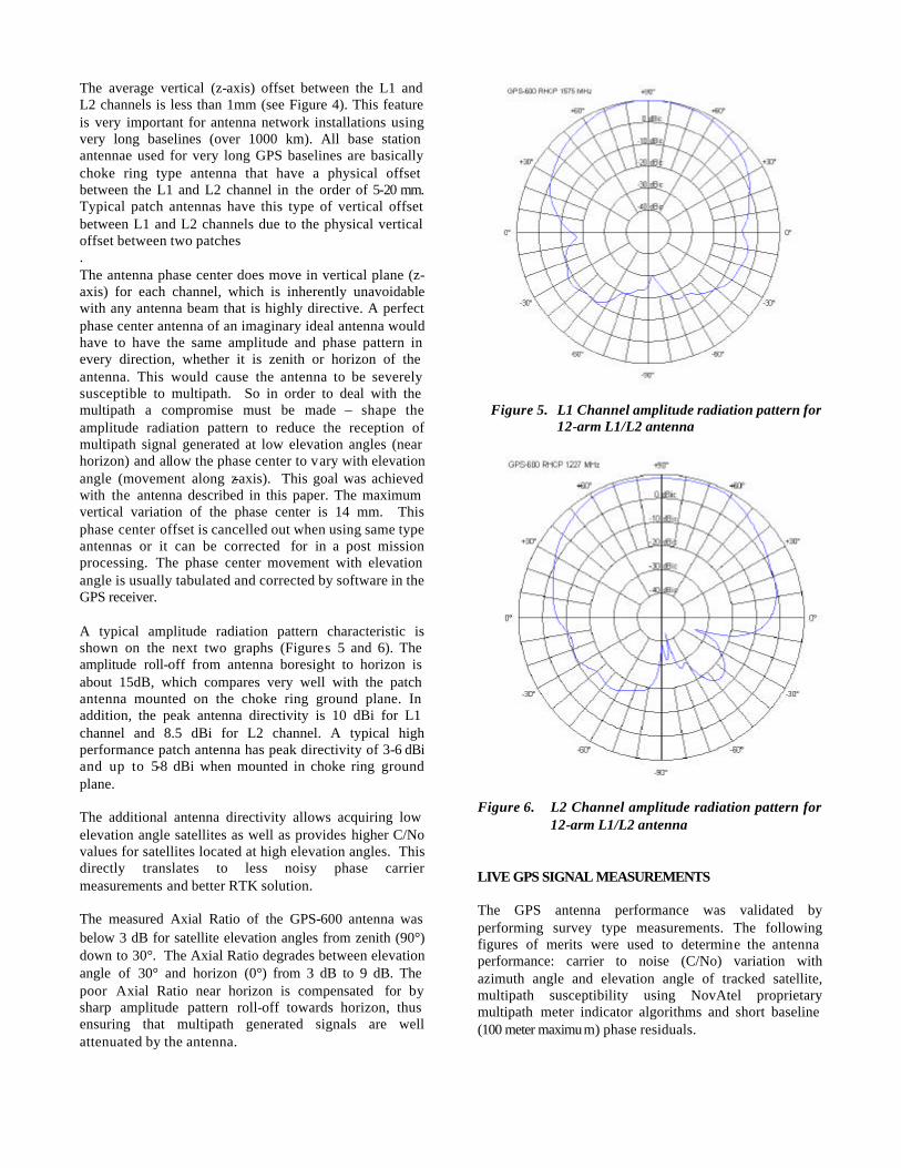
The average vertical (z-axis) offset between the L1 and L2 channels is less than 1mm (see Figure 4). This feature is very important for antenna network installations using very long baselines (over 1000 km). All base station antennae used for very long GPS baselines are basically choke ring type antenna that have a physical offset between the L1 and L2 channel in the order of 5-20 mm. Typical patch antennas have this type of vertical offset between L1 and L2 channels due to the physical vertical offset between two patches . The antenna phase center does move in vertical plane (z-axis) for each channel, which is inherently unavoidable with any antenna beam that is highly directive. A perfect phase center antenna of an imaginary ideal antenna would have to have the same amplitude and phase pattern in every direction, whether it is zenith or horizon of the antenna. This would cause the antenna to be severely susceptible to multipath. So in order to deal with the multipath a compromise must be made – shape the amplitude radiation pattern to reduce the reception of multipath signal generated at low elevation angles (near horizon) and allow the phase center to vary with elevation angle (movement along z-axis). This goal was achieved with the antenna described in this paper. The maximum vertical variation of the phase center is 14 mm. This phase center offset is cancelled out when using same type antennas or it can be corrected for in a post mission processing. The phase center movement with elevation angle is usually tabulated and corrected by software in the GPS receiver. A typical amplitude radiation pattern characteristic is shown on the next two graphs (Figures 5 and 6). The amplitude roll-off from antenna boresight to horizon is about 15dB, which compares very well with the patch antenna mounted on the choke ring ground plane. In addition, the peak antenna directivity is 10 dBi for L1 channel and 8.5 dBi for L2 channel. A typical high performance patch antenna has peak directivity of 3-6 dBi and up to 5-8 dBi when mounted in choke ring ground plane. The additional antenna directivity allows acquiring low elevation angle satellites as well as provides higher C/No values for satellites located at high elevation angles. This directly translates to less noisy phase carrier measurements and better RTK solution. The measured Axial Ratio of the GPS-600 antenna was below 3 dB for satellite elevation angles from zenith (90°) down to 30°. The Axial Ratio degrades between elevation angle of 30° and horizon (0°) from 3 dB to 9 dB. The poor Axial Ratio near horizon is compensated for by sharp amplitude pattern roll-off towards horizon, thus ensuring that multipath generated signals are well attenuated by the antenna.
Figure 5. L1 Channel amplitude radiation pattern for
12-arm L1/L2 antenna
Figure 6. L2 Channel amplitude radiation pattern for
12-arm L1/L2 antenna LIVE GPS SIGNAL MEASUREMENTS The GPS antenna performance was validated by performing survey type measurements. The following figures of merits were used to determine the antenna performance: carrier to noise (C/No) variation with azimuth angle and elevation angle of tracked satellite, multipath susceptibility using NovAtel proprietary multipath meter indicator algorithms and short baseline (100 meter maximum) phase residuals.
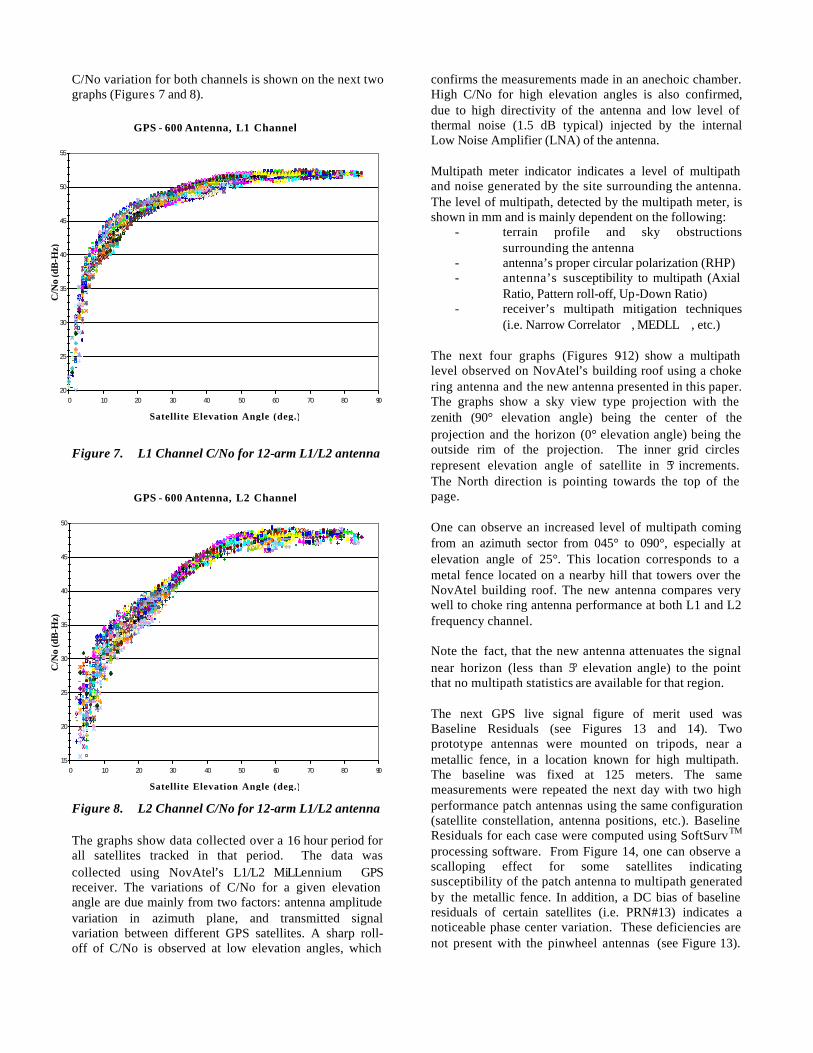
C/No variation for both channels is shown on the next two graphs (Figures 7 and 8).
Figure 7. L1 Channel C/No for 12-arm L1/L2 antenna
Figure 8. L2 Channel C/No for 12-arm L1/L2 antenna The graphs show data collected over a 16 hour period for all satellites tracked in that period. The data was collected using NovAtel’s L1/L2 MiLLennium GPS receiver. The variations of C/No for a given elevation angle are due mainly from two factors: antenna amplitude variation in azimuth plane, and transmitted signal variation between different GPS satellites. A sharp roll-off of C/No is observed at low elevation angles, which
confirms the measurements made in an anechoic chamber. High C/No for high elevation angles is also confirmed, due to high directivity of the antenna and low level of thermal noise (1.5 dB typical) injected by the internal Low Noise Amplifier (LNA) of the antenna. Multipath meter indicator indicates a level of multipath and noise generated by the site surrounding the antenna. The level of multipath, detected by the multipath meter, is shown in mm and is mainly dependent on the following:
- terrain profile and sky obstructions surrounding the antenna
- antenna’s proper circular polarization (RHP) - antenna’s susceptibility to multipath (Axial
Ratio, Pattern roll-off, Up-Down Ratio) - receiver’s multipath mitigation techniques
(i.e. Narrow Correlator, MEDLL, etc.) The next four graphs (Figures 9-12) show a multipath level observed on NovAtel’s building roof using a choke ring antenna and the new antenna presented in this paper. The graphs show a sky view type projection with the zenith (90° elevation angle) being the center of the projection and the horizon (0° elevation angle) being the outside rim of the projection. The inner grid circles represent elevation angle of satellite in 5° increments. The North direction is pointing towards the top of the page. One can observe an increased level of multipath coming from an azimuth sector from 045° to 090°, especially at elevation angle of 25°. This location corresponds to a metal fence located on a nearby hill that towers over the NovAtel building roof. The new antenna compares very well to choke ring antenna performance at both L1 and L2 frequency channel. Note the fact, that the new antenna attenuates the signal near horizon (less than 5° elevation angle) to the point that no multipath statistics are available for that region. The next GPS live signal figure of merit used was Baseline Residuals (see Figures 13 and 14). Two prototype antennas were mounted on tripods, near a metallic fence, in a location known for high multipath. The baseline was fixed at 125 meters. The same measurements were repeated the next day with two high performance patch antennas using the same configuration (satellite constellation, antenna positions, etc.). Baseline Residuals for each case were computed using SoftSurvTM processing software. From Figure 14, one can observe a scalloping effect for some satellites indicating susceptibility of the patch antenna to multipath generated by the metallic fence. In addition, a DC bias of baseline residuals of certain satellites (i.e. PRN#13) indicates a noticeable phase center variation. These deficiencies are not present with the pinwheel antennas (see Figure 13).
G P S - 6 0 0 A n t e n n a , L 1 C h a n n e l
20
25
30
35
40
45
50
55
0 10 20 30 40 50 60 70 80 90
S a t e l l i t e E l e v a t i o n A n g l e ( d e g . )
C/N
o (d
B-H
z)
G P S - 6 0 0 A n t e n n a , L 2 C h a n n e l
15
20
25
30
35
40
45
50
0 10 20 30 40 50 60 70 80 90
S a t e l l i t e E l e v a t i o n A n g l e ( d e g . )
C/N
o (d
B-H
z)
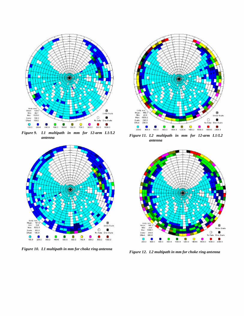
Figure 9. L1 multipath in mm for 12-arm L1/L2 antenna
Figure 10. L1 multipath in mm for choke ring antenna
Figure 11. L2 multipath in mm for 12-arm L1/L2 antenna
Figure 12. L2 multipath in mm for choke ring antenna
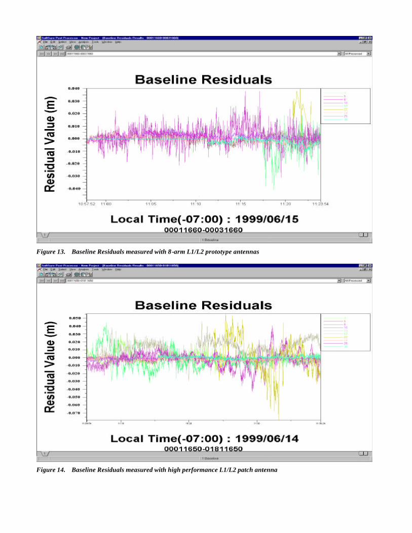
Figure 13. Baseline Residuals measured with 8-arm L1/L2 prototype antennas
Figure 14. Baseline Residuals measured with high performance L1/L2 patch antenna
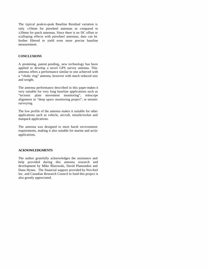
The typical peak-to-peak Baseline Residual variation is only ±10mm for pinwheel antennas as compared to ±20mm for patch antennas. Since there is no DC offset or scalloping effects with pinwheel antennas, data can be further filtered to yield even more precise baseline measurement. CONCLUSIONS A promising, patent pending, new technology has been applied to develop a novel GPS survey antenna. This antenna offers a performance similar to one achieved with a “choke ring” antenna, however with much reduced size and weight. The antenna performance described in this paper makes it very suitable for very long baseline applications such as “tectonic plate movement monitoring”, telescope alignment in “deep space monitoring project”, or seismic surveying. The low profile of the antenna makes it suitable for other applications such as vehicle, aircraft, missile/rocket and manpack applications. The antenna was designed to meet harsh environment requirements, making it also suitable for marine and arctic applications. ACKNOWLEDGMENTS The author gratefully acknowledges the assistance and help provided during this antenna research and development by Mike Blarowski, David Plamondon and Dana Hynes. The financial support provided by NovAtel Inc. and Canadian Research Council to fund this project is also greatly appreciated.