a novel hybrid system for the fabrication of a fibrous...
TRANSCRIPT
A
BMa
b
c
d
a
ARRAA
KCMMPF
1
tmaTnmr(P
1mp2s(itrm
0d
Carbohydrate Polymers 89 (2012) 222– 229
Contents lists available at SciVerse ScienceDirect
Carbohydrate Polymers
j ourna l ho me pag e: www.elsev ier .com/ locate /carbpol
novel hybrid system for the fabrication of a fibrous mesh with micro-inclusions
ilal Ahmada, Oguzhan Gunduza,b, Simeon Stoyanovc, Eddie Pelanc, Eleanor Stridea,d,ohan Edirisinghea,∗
Department of Mechanical Engineering, University College London, Torrington Place, London WC1E 7JE, UKMaterials Department, Technical Education Faculty, Marmara University, Goztepe, Istanbul 34722, TurkeyUnilever Research, Olivier van Noortlaan 120, 3130 AC Vlaardingen, The NetherlandsInstitute of Biomedical Engineering, University of Oxford, Headington, Oxford OX3 7DQ, UK
r t i c l e i n f o
rticle history:eceived 3 February 2012eceived in revised form 27 February 2012ccepted 29 February 2012vailable online 7 March 2012
a b s t r a c t
A novel hybrid system combining microfluidic and co-axial electrospinning techniques has been used togenerate different types of fibre structures with varied desirable inclusions using food grade polymers,ethyl cellulose and sodium alginate. The processing conditions in the microfluidic T-junction device,i.e. gas pressure and liquid flow rate were adjusted in order to generate near-monodisperse microbub-bles which subsequently serve as a platform for particle generation. These particles exhibit micro-scale
eywords:o-axial electrospinningicrofluidicsicrobubbles
articles
diameters and different shapes and some bubbles were incorporated into the fibrous mesh prepared byconcurrent electrospinning. The fibre/particle structures obtained with different polymers via this novelmethod could potentially have many applications in various engineering and biological sectors.
© 2012 Elsevier Ltd. All rights reserved.
ibrous mesh
. Introduction
Control over structural parameters such as aspect ratio, inhe case of fibre formation, and monodispersity, in the case of
icrobubbles, cannot be achieved via conventional methods suchs drawing and sonication, respectively (Ramakrishna, Fujihara,eo, Lim, & Ma, 2005; Unger et al., 2004). In contrast, electrospin-ing and microfluidic techniques offer better control over fibre andicrobubble formation and have the added advantage of producing
eproducible and, in the case of electrospinning, scalable structuresDendukuri & Doyle, 2009; Seiffert, 2011; Seo et al., 2005; Stride,ancholi, Edirisinghe, & Samarasinghe, 2008).
Since its inception over a century ago (Cooley, 1902; Morton,902), the primary focus of research into electrostatic fibre for-ation or “electrospinning” has been mostly the fundamental
hysics underlying the process (Doshi & Reneker, 1995; Feng,003) and its application in biomedical engineering for con-tructing wound dressings and tissue scaffolds for organ therapyAgarwal, Wendorff, & Greiner, 2008). Electrospinning has emergedn recent years as a popular choice for producing continuous
hreads, fibre arrays and non-woven fabrics from a range of mate-ials including polymers, ceramics, composites and food-gradeaterials with a range of diameters (1–100 �m) (Ramakrishna∗ Corresponding author.E-mail address: [email protected] (M. Edirisinghe).
144-8617/$ – see front matter © 2012 Elsevier Ltd. All rights reserved.oi:10.1016/j.carbpol.2012.02.074
et al., 2005; Wongsasulak et al., 2010). Electrospun fibres at thisscale have a number of desirable characteristics such as very largesurface area to volume ratio, flexibility to incorporate surface func-tionalities, and superior mechanical properties (e.g. stiffness andtensile strength) (Huang, Zhang, Kotaiki, & Ramakrishna, 2003). Thepotential of electrospinning has also been demonstrated to attainconformity between size and output rates of fibres (Petras et al.,2007). Furthermore, electrospinning is relatively a robust and sim-ple technique to produce nanofibres which offer several additionaladvantages such as adjustable porosity and the ability to producestructures with a wide vareity of sizes and shapes. Because of theseadvantages, electrospun nanofibres have also been widely inves-tigated for its use in applications such as filtration, optical andchemical sensors and as electrode materials (Liang, Hsiao, & Chu,2007). However, a well known limitation of the electrospinningprocess is the level of fibre productivity, which is very much lowerthan that of a current fibre technology (Teo & Ramakrishna, 2006).A simple method of increasing the productivity of electrospinninghas been illustrated by the increase in the number of spinneretsused in the process (Ding, Kimura, Sato, Fujita, & Shiratori, 2004).While the production speeds of fibre formation have increased,other disadvantages to the electrospinning process that have beendeterrents to the manufacturing on a large scale include safety and
environmental issues of the toxic solvents used in the spin dopesand the high voltages involved in the electrospinning process.Moreover, solvent removal and recovery increase manufacturingcosts. One of the ways forward is to develop polymer/solvent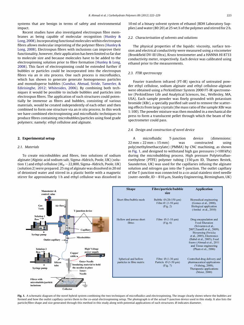
ate Po
si
bLfiLfte2bfiwaEnetmcwpp
2
2
at(os
Ffp
B. Ahmad et al. / Carbohydr
ystems that are benign in terms of safety and environmentalmpact.
Recent studies have also investigated electrospun fibre mem-ranes as being capable of molecular recognition (Hunley &ong, 2008). Incorporating functional molecules within electrospunbres allows molecular imprinting of the polymer fibres (Hunley &ong, 2008). Electrospun fibres with inclusions can improve theirunctionality, however, their application has been limited so far dueo molecule size and because molecules have to be added to thelectrospinning solution prior to fibre formation (Hunley & Long,008). This facet of electrospinning could be extended further ifubbles or particles could be incorporated into the electrospunbres via an in situ process. One such process is microfluidics,hich has shown to generate generate homogeneous particles
nd monodisperse bubbles (Gunduz, Ahmad, Stride, Tamerler, &dirisinghe, 2012; Whitesides, 2006). By combining both tech-iques it would be possible to include bubbles and particles intolectrospun fibres. The application of such structures could poten-ially be immense as fibres and bubbles, consisting of various
aterials, would be created independently of each other and thenombined to form one structure via an in situ process. In this worke have combined electrospinning and microfluidic techniques toroduce fibres containing microbubbles/particles using food gradeolymers; namely: ethyl cellulose and alginate.
. Experimental setup
.1. Materials
To create microbubbles and fibres, two solutions of sodiumlginate (Alginic acid sodium salt, Sigma–Aldrich, Poole, UK) (solu-
ion 1) and ethyl cellulose (Mw ∼ 22,800, Sigma–Aldrich, Poole, UK)solution 2) were prepared. 25 mg of alginate was dissolved in 20 mlf deionised water and stirred in a plastic bottle with a magnetictirrer for approximately 1 h and ethyl cellulose was dissolved inig. 1. A schematic diagram of the novel hybrid system combining the two techniques oformed and how the outlet capillary carries them to the co-axial electrospinning setup. Tarticle/fibre shape and size generated through this method in this study along with pote
lymers 89 (2012) 222– 229 223
10 ml of a binary solvent system of ethanol (BDH Laboratory Sup-plies) and water (80:20) at 25 wt.% of the polymer and stirred for 2 h.
2.2. Characterisation of solvents and solutions
The physical properties of the liquids: viscosity, surface ten-sion and electrical conductivity were measured using a viscometer(Brookfield DV-III Ultra), Kruss tensiometer and a HANNA HI 8733conductivity meter, respectively. Each device was calibrated usingethanol prior to the measurements.
2.3. FTIR spectroscopy
Fourier transform infrared (FT-IR) spectra of untreated pow-der ethyl cellulose, sodium alginate and ethyl cellulose-alginatewere obtained using a PerkinElmer System 2000 FT-IR spectrome-ter (PerkinElmer Life and Analytical Sciences, Inc., Wellesley, MA,USA). Each sample powder was finely grounded with potassiumbromide (KBr), a specially purified salt used to remove the scatter-ing effects from large crystals (the mass ratio of the sample:KBr was1:100). The powder mixture was then moulded in a mechanical diepress to form a translucent pellet through which the beam of thespectrometer could pass.
2.4. Design and construction of novel device
A microfluidic T-junction device (dimensions:22 mm × 22 mm × 15 mm) was constructed usingpoly(methylmethacrylate) (PMMA) by CNC machining, as shownin Fig. 1, and designed to withstand high gas pressures (>100 kPa)during the microbubbling process. High pressure Polytetrafluo-roethylene (PTFE) polymer tubing (150 �m ID, Thames Restek,
Saunderton, UK) was used for the capillaries infusing the alginatesolution and nitrogen gas into the T-junction. The outlet capillaryof the T-junction was connected to a co-axial stainless steel needle(outer-needle, ID ∼ 810 �m, Stanley Engineering, Birmingham, UK)microfluidics and electrospinning. The image clearly shows where the bubbles arehe photograph is of the actual T-junction device used in this study. It also lists thential applications of such structures. Ø indicates diameter.
224 B. Ahmad et al. / Carbohydrate Polymers 89 (2012) 222– 229
F robuba ique,
vsBaG
2
7lactiacdmc
2
etaPosfissfitwm
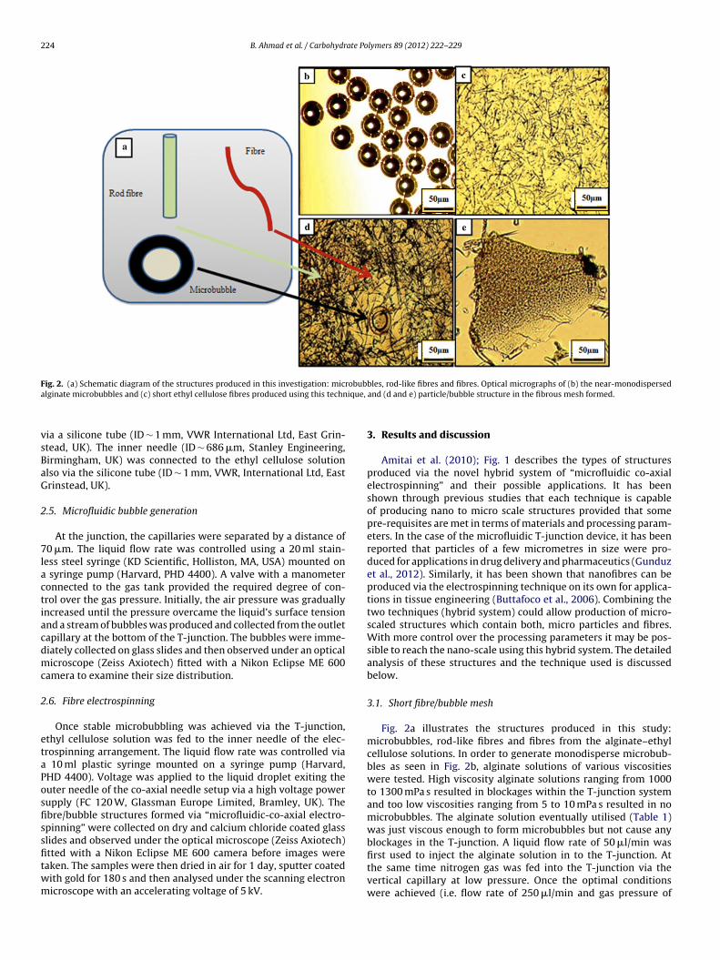
ig. 2. (a) Schematic diagram of the structures produced in this investigation: miclginate microbubbles and (c) short ethyl cellulose fibres produced using this techn
ia a silicone tube (ID ∼ 1 mm, VWR International Ltd, East Grin-tead, UK). The inner needle (ID ∼ 686 �m, Stanley Engineering,irmingham, UK) was connected to the ethyl cellulose solutionlso via the silicone tube (ID ∼ 1 mm, VWR, International Ltd, Eastrinstead, UK).
.5. Microfluidic bubble generation
At the junction, the capillaries were separated by a distance of0 �m. The liquid flow rate was controlled using a 20 ml stain-
ess steel syringe (KD Scientific, Holliston, MA, USA) mounted on syringe pump (Harvard, PHD 4400). A valve with a manometeronnected to the gas tank provided the required degree of con-rol over the gas pressure. Initially, the air pressure was graduallyncreased until the pressure overcame the liquid’s surface tensionnd a stream of bubbles was produced and collected from the outletapillary at the bottom of the T-junction. The bubbles were imme-iately collected on glass slides and then observed under an opticalicroscope (Zeiss Axiotech) fitted with a Nikon Eclipse ME 600
amera to examine their size distribution.
.6. Fibre electrospinning
Once stable microbubbling was achieved via the T-junction,thyl cellulose solution was fed to the inner needle of the elec-rospinning arrangement. The liquid flow rate was controlled via
10 ml plastic syringe mounted on a syringe pump (Harvard,HD 4400). Voltage was applied to the liquid droplet exiting theuter needle of the co-axial needle setup via a high voltage powerupply (FC 120 W, Glassman Europe Limited, Bramley, UK). Thebre/bubble structures formed via “microfluidic-co-axial electro-pinning” were collected on dry and calcium chloride coated glasslides and observed under the optical microscope (Zeiss Axiotech)
tted with a Nikon Eclipse ME 600 camera before images wereaken. The samples were then dried in air for 1 day, sputter coatedith gold for 180 s and then analysed under the scanning electronicroscope with an accelerating voltage of 5 kV.bles, rod-like fibres and fibres. Optical micrographs of (b) the near-monodispersedand (d and e) particle/bubble structure in the fibrous mesh formed.
3. Results and discussion
Amitai et al. (2010); Fig. 1 describes the types of structuresproduced via the novel hybrid system of “microfluidic co-axialelectrospinning” and their possible applications. It has beenshown through previous studies that each technique is capableof producing nano to micro scale structures provided that somepre-requisites are met in terms of materials and processing param-eters. In the case of the microfluidic T-junction device, it has beenreported that particles of a few micrometres in size were pro-duced for applications in drug delivery and pharmaceutics (Gunduzet al., 2012). Similarly, it has been shown that nanofibres can beproduced via the electrospinning technique on its own for applica-tions in tissue engineering (Buttafoco et al., 2006). Combining thetwo techniques (hybrid system) could allow production of micro-scaled structures which contain both, micro particles and fibres.With more control over the processing parameters it may be pos-sible to reach the nano-scale using this hybrid system. The detailedanalysis of these structures and the technique used is discussedbelow.
3.1. Short fibre/bubble mesh
Fig. 2a illustrates the structures produced in this study:microbubbles, rod-like fibres and fibres from the alginate–ethylcellulose solutions. In order to generate monodisperse microbub-bles as seen in Fig. 2b, alginate solutions of various viscositieswere tested. High viscosity alginate solutions ranging from 1000to 1300 mPa s resulted in blockages within the T-junction systemand too low viscosities ranging from 5 to 10 mPa s resulted in nomicrobubbles. The alginate solution eventually utilised (Table 1)was just viscous enough to form microbubbles but not cause anyblockages in the T-junction. A liquid flow rate of 50 �l/min was
first used to inject the alginate solution in to the T-junction. Atthe same time nitrogen gas was fed into the T-junction via thevertical capillary at low pressure. Once the optimal conditionswere achieved (i.e. flow rate of 250 �l/min and gas pressure of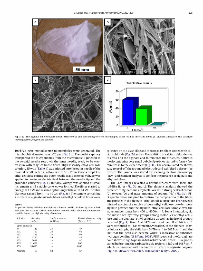
B. Ahmad et al. / Carbohydrate Polymers 89 (2012) 222– 229 225
F ron ms
1mtttsceagieda
TPip
ig. 3. (a) The alginate–ethyl cellulose fibrous structure, (b and c) scanning electhowing carbon, oxygen and sodium.
00 kPa), near-monodisperse microbubbles were generated. Theicrobubble diameter was ∼70 �m (Fig. 2b). The outlet capillary
ransported the microbubbles from the microfluidic T-junction tohe co-axial needle setup via the inner needle, ready to be elec-rospun with ethyl cellulose fibres. High viscosity ethyl celluloseolution, 25 wt.% (Table 1) was injected into the outer needle of theo-axial needle setup at a flow rate of 50 �l/min. Once a droplet ofthyl cellulose exiting the outer needle was observed, voltage waspplied to create an electric field between the needle tip and therounded collector (Fig. 1). Initially, voltage was applied at smallncrements until a stable-cone jet was formed. The fibres started to
merge at 12 kV and reached optimum yield level at 14 kV. The fibreiameter ranged from 1 to 10 �m (Fig. 2c). The sample containingmixture of alginate microbubbles and ethyl cellulose fibres were
able 1roperties of ethyl cellulose and alginate solutions used in this investigation. A dashndicates that accurate surface tension measurements with plate method were notossible due to the high viscosity of solution.
Solution Viscosity(mPa s)
Surface tension(mN/m)
Electrical conductivity(S/m × 10−4)
Ethyl cellulose5% 23 25 4710% 100 29 6115% 363 36 6820% 1230 54 8425% 3692 – 8030% 11,629 – 80035% 14,600 – 1100
Alginate 13 63 67
icrographs of the rod-like fibres and fibres, (d) element analysis of this structure
collected on to a glass slide and then on glass slides coated with cal-cium chloride (Fig. 2d and e). The addition of calcium chloride wasto cross-link the alginate and to reinforce the structure. A fibrousmesh containing very small bubbles/particles started to form a fewminutes in to the experiment (Fig. 3a). The accumulated mesh waseasy to peel-off the grounded electrode and exhibited a tissue-liketexture. The sample was stored for scanning electron microscopy(SEM) and element analysis to confirm the presence of alginate andethyl cellulose.
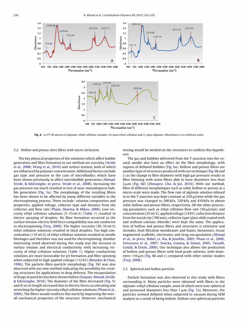
The SEM images revealed a fibrous structure with short androd-like fibres (Fig. 3b and c). The element analysis showed thepresence of alginate and ethyl cellulose with strong peaks of carbon(C), oxygen (O) and trace amounts of sodium (Na) (Fig. 3d). FT-IR spectra were analysed to confirm the composition of the fibresand particles in the alginate–ethyl cellulose structure. Fig. 4 revealsinfrared spectra of samples of pure ethyl cellulose powder, purealginate powder and the alginate–ethyl cellulose sample over thewavenumber range from 400 to 4000 cm−1. Some interaction, viathe substituted hydroxyl groups among molecules of ethyl cellu-lose and the alginate–ethyl cellulose as well as hydroxyl groups,occurred (Fig. 4). Band A at 3479 cm−1 and band B at 3475 cm−1
were attributed to OH stretching/vibration. In the alginate–ethylcellulose sample, the shift from 3479 cm−1 to 3475 cm−1 and thefact that the peak also became wider is indicative of enhancedhydrogen bonding (Li & Yang, 2008). FTIR spectra of the Ca–alginate
bond shown in Fig. 4a possess distinctive bands in the O H region asstated before, and the carboxylic acid regions, 1380 and 1417 cm−1which is consistent with the known structure of alginate polymer(Fig. 4c) (Stewart, Yau, Allen, Branbander, & Flyn, 2009).
226 B. Ahmad et al. / Carbohydrate Polymers 89 (2012) 222– 229
re eth
3
geagbSgbhepccestecbiscsw1oio&as2a
Fig. 4. (a) FT-IR spectra of alginate–ethyl cellulose samples, (b) pu
.2. Hollow and porous short fibres with micro-inclusions
The key physical properties of the solutions which affect bubbleeneration and fibre formation in our method are viscosity (Stridet al., 2008; Wang et al., 2010) and surface tension, both of whichre influenced by polymer concentration. Additional factors includeas type and pressure in the case of microfluidics which haveeen shown previously to affect microbubble generation (Ahmad,tride, & Edirisinghe, in press; Stride et al., 2008). Increasing theas pressure too much resulted in loss of near-monodisperse bub-le generation (Fig. 5a). The morphology of the resulting fibresas been shown to be affected by many different variables in thelectrospinning process. These include: solution composition androperties, applied voltage, collector type and distance from theollector and flow rate (Pham, Sharma, & Mikos, 2006). Low vis-osity ethyl cellulose solutions (5–15 wt.%) (Table 1) resulted inlectro spraying of droplets. No fibre formation occurred as theurface tension-electric field force compatibility was not conduciveo electrospinning (Frey, 2008). The higher viscosity (30–35 wt.%)thyl cellulose solutions resulted in thick droplets. Too high con-entration (>35 wt.%) of ethyl cellulose solution resulted in needlelockages and therefore was not used for electrospinning. Another
nteresting trend observed during this study was the increase inurface tension and electrical conductivity with increasing vis-osity of ethyl cellulose solutions (Table 1). Higher conductivityolutions are more favourable for jet formation and fibre spinninghen subjected to high applied voltage (>12 kV) (Reneker & Chun,
996). The particle–fibre–particle morphology (Fig. 5b) was alsobserved with our new method indicating the possibility for creat-ng structures for applications in drug delivery. The encapsulationf drugs in particles has been shown before (Enayati, Ahmad, Stride,
Edirisinghe, 2010). The diameter of the fibre decreased (Fig. 5c
nd d) as its length increased due to electric forces accelerating andtretching the higher viscosity ethyl cellulose solutions (Pham et al.,006). The fibres would reinforce this mesh by improving the over-ll mechanical properties of the structure. However, mechanicalyl cellulose and (c) pure alginate. Absorbance is in arbitrary units.
testing would be needed on the structures to confirm this hypoth-esis.
The gas and bubbles delivered from the T-junction into the co-axial needle also have an effect on the fibre morphology, withregions of deflated bubbles (Fig. 6a). Hollow and porous fibres areanother type of structures produced with our technique (Fig. 6b andc) as the change in fibre diameter with high gas pressure results infibre thinning with some fibres able to have diameters less than2 �m (Fig. 6d) (Zhmayev, Cho, & Joo, 2010). With our method,fibre of different morphologies such as solid, hollow or porous at amicro-scale were made. The flow rate of alginate solution infusedin to the T-junction was kept constant at 250 �l/min while the gaspressure was changed to 200 kPa, 320 kPa and 410 kPa to obtainsolid, hollow and porous fibres, respectively. All the other process-ing parameters such as ethyl cellulose flow rate (50 �l/min) andconcentration (25 wt.%), applied voltage (14 kV), collection distancefrom the nozzle tip (100 mm), collector type (glass slide coated withand without calcium chloride) were kept the same. The applica-tion of hollow and porous fibres and structures is extensive andincludes, food filtration membranes and foams, biosensors, tissueengineered scaffolds, electronics and drug encapsulation (Ahmadet al., in press; Babel, Li, Xia, & Jenekhe, 2005; Pham et al., 2006;Srivastava et al., 2007; Swicka, Gouma, & Simon, 2005; Tasselli,Conidi, & Drioli, 2009). Our technique also allows the productionof hollow and porous fibres with food grade solvents, with diam-eters <10 �m (Fig. 6b and c) compared with other similar studies(Frey, 2008).
3.3. Spherical and hollow particles
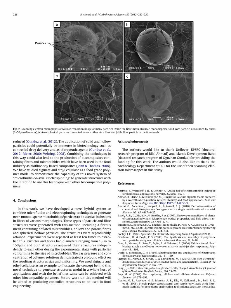
Particle formation was also observed in this study with fibressurrounding it. Many particles were obtained with fibres in the
alginate–ethyl cellulose sample, some of which were non-sphericaland possessed diameters less than 1 �m (Fig. 7a). Moreover, theparticles seemed deflated when subjected to vacuum during SEManalysis as a result of being hollow. Hollow core spherical particles
B. Ahmad et al. / Carbohydrate Polymers 89 (2012) 222– 229 227
F via tm f the
wtdwt
Fi
ig. 5. (a) Optical micrograph of the polydisperse alginate microbubbles generatedorphology, (c) the fibrous mesh containing rod fibres and (d) cross-section view o
ere also generated through the technique. The scanning elec-ron micrographs indicate near spherical particles (Fig. 7b) with
iameters just over 10 �m and in some instances these particlesere connected to each other via a fibre (Fig. 7c). It is also evidenthrough the SEM images that this technique also has the ability
ig. 6. Scanning electron micrographs of (a) deflated bubbles with fibres, (b) hollow fibremage, (c) porous fibres and (d) deflated particle, bubbles and fibres.
he T-junction device. Scanning electron micrographs of (b) particle–fibre–particlesample shown in Fig. 3a.
to produce particles which are hollow (Fig. 7d). The occurrence ofsuch particles is highly dependent on gas pressure and type and
the polymer solution to make the monodisperse microbubbles viathe microfluidic T-junction device. With more control over bub-ble generation via the T-junction, these diameters can further bes and a high magnification (×7500) image of a hollow fibre on the right side of the
228 B. Ahmad et al. / Carbohydrate Polymers 89 (2012) 222– 229
F s insi( and (d
rpc2ttiWm“tm
4
cnismaal1dcctenaobe
ig. 7. Scanning electron micrographs of (a) low resolution image of many particle1–50 �m diameter), (c) two spherical particles connected to each other via a fibre
educed (Gunduz et al., 2012). The application of solid and hollowarticles could potentially be immense in biotechnology such asontrolled drug delivery and as therapeutic agents (Gunduz et al.,012; Meier, 2000; Vehring, 2008). Combining the techniques inhis way could also lead to the production of biocomposites con-aining fibres and microbubbles which have been used in the foodndustry as biofibre-soy based composites (John & Thomas, 2008).
e have studied alginate and ethyl cellulose as a food grade poly-er model to demonstrate the capability of this novel system of
microfluidic-co-axial electrospinning” to generate structures withhe intention to use this technique with other biocompatible poly-
ers.
. Conclusions
In this work, we have developed a novel hybrid system toombine microfluidic and electrospinning techniques to generateear-monodisperse microbubbles/particles to be used as inclusions
n fibres of various morphologies. Three types of particle and fibretructures were generated with this method, including a fibrousesh containing deflated microbubbles, hollow and porous fibres
nd spherical hollow particles. The structures were reproduciblyttained; experiments were repeated at least ten times to estab-ish this. Particles and fibres had diameters ranging from 1 �m to50 �m, and both structures acquired their structures indepen-ently to each other during the experimental stage with particlesonforming to the size of microbubbles. The gas pressure and con-entration of polymer solutions demonstrated a profound effect onhe resulting structures size and uniformity. We used alginate andthyl cellulose as an example to illustrate the concept behind thisovel technique to generate structures useful in a whole host of
pplications and with the belief that same can be achieved withther biocompatible polymers. Future work on this method wille aimed at producing controlled structures to be used in foodngineering.de the fibre mesh, (b) near-monodisperse solid-core particle surrounded by fibres) hollow particle in the fibre mesh.
Acknowledgements
The authors would like to thank Unilever, EPSRC (doctoralresearch program of Bilal Ahmad) and Islamic Development Bank(doctoral research program of Oguzhan Gundaz) for providing thefunding for this work. The authors would also like to thank theArchaeology Department at UCL for the use of their scanning elec-tron microscopes in this study.
References
Agarwal, S., Wendorff, J. H., & Greiner, A. (2008). Use of electrospinning techniquefor biomedical applications. Polymer, 49, 5603–5621.
Ahmad, B., Stride, E., & Edirisinghe, M. J. (in press). Calcium alginate foams preparedby a microfluidic T-junction system: Stability and food applications. Food andBioprocess Technology, doi:10.1007/s11947-011-0650-3.
Amitai, G., Andersen, J., Koepsel, R., & Russell, A. J. (2010). Decontamination ofchemical and biological warfare agents with a single multifunctional material.Biomaterials, 15, 4417–4425.
Babel, A., Li, D., Xia, Y. N., & Jenekhe, S. A. (2005). Electrospun nanofibres of blendsof conjugated polymers: Morphology, optical properties, and field effect tran-sistors. Macromolecules, 38, 4705–4771.
Buttafoco, L., Kolkman, N. G., Engbers-Buijtenhuijs, P., Poot, A. A., Dijkstra, P. J., Ver-mes, I., et al. (2006). Electrospinning of collagen and elastin for tissue engineeringapplications. Biomaterials, 27, 724–734.
Cooley, J. F. (1902). Apparatus for electrically dispersing fluids. US patent 692631.Dendukuri, D., & Doyle, P. S. (2009). The Synthesis and assembly of polymeric
microparticles using microfluidics. Advanced Materials, 21, 1–16.Ding, B., Kimura, E., Sato, T., Fujita, S., & Shiratori, S. (2004). Fabrication of blend
biodegradable nanofibrous nonwoven mats via multi-jet electrospinning. Poly-mer, 45, 1895.
Doshi, J., & Reneker, D. H. (1995). Electrospinning and applications of electrospunfibers. Journal of Electrostatics, 35, 151–160.
Enayati, M., Ahmad, Z., Stride, E., & Edirisinghe, M. J. (2010). One-step electrohy-drodynamic production of drug-loaded micro and nanoparticles. Journal of TheRoyal Society Interface, 7, 667–675.
Feng, J. J. (2003). Strecthing of a straight electrically charged viscoelastic jet. Journalof Non-Newtonian Fluid Mechanics, 116, 55–70.
Frey, M. W. (2008). Electrospinning cellulose and cellulose derivatives. PolymerReviews, 48, 378–391.
Gomes, M. E., Azevedo, H. S., Moreira, A. R., Ella, V., Kellomaki, M., Reis, R. L.,et al. (2008). Starch–poly(�-caprolactone) and starch–poly(lactic acid) fibre-mesh scaffolds for bone tissue engineering applications: Structure, mechanical

ate Po
G
H
H
J
L
L
MMP
P
R
R
S
S
Wongsasulak, S., Patapeejumruswong, M., Weiss, J., Supaphol, P., & Yoovidhya, T.
B. Ahmad et al. / Carbohydr
properties and degradation behaviour. Journal of Tissue Engineering and Regen-erative Medicine, 2, 243–252.
unduz, O., Ahmad, Z., Stride, E., Tamerler, C., & Edirisinghe, M. (2012). Bioinspiredbubble design for particle generation. Journal of Royal Soiety Interface, 9(67),389–395.
uang, Z. M., Zhang, Y. Z., Kotaiki, M., & Ramakrishna, S. (2003). A review on poly-mer nanofibers by electrospinning and their applications in nanocomposites.Composites Science and Technology, 63, 2223.
unley, M. T., & Long, T. E. (2008). Perspective Electrospinning functional nanoscalefibres: A perspective for the future. Polymer International, 57, 385–389.
ohn, M. J., & Thomas, S. (2008). Biofibres and biocomposites. Carbohydrate Polymers,71, 343–364.
i, X. W., & Yang, T. F. (2008). Fabrication of ethyl cellulose microspheres: Chitosansolution as a stabilizer. Korean Journal of Chemical Engineering, 25, 1201–1204.
iang, D., Hsiao, B. S., & Chu, B. (2007). Functional electrospun nanofibrous scaffoldsfor biomedical applications. Advanced Drug delivery Reviews, 59, 1392–1412.
eier, W. (2000). Polymer nanocapsules. Chemical Society Reviews, 29, 295.orton, W. J. (1902). Method of dispersing fluids. US patent 705691.
etras, D., Mares, L., Cmelik, J., & Fiala, K. (2007). Device for production of nanofibresby electrostatic spinning of polymer solutions. Patent WO/2007/137530.
ham, Q. P., Sharma, U., & Mikos, A. G. (2006). Electrospinning of polymericnanofibers for tissue engineering applications: A review. Tissue Engineering, 12,1197–1211.
amakrishna, S., Fujihara, K., Teo, W. E., Lim, T. C., & Ma, Z. (2005). An introduction toelectrospinning and nanofibers. Singapore: World Scientific. Chapter 1
eneker, D. H., & Chun, I. (1996). Nanometre diameter fibres of polymer produced
by electrospinning. Nanotechnology, 7, 216.eo, M., Nie, Z. H., Xu, S. Q., Lewis, P. C., Graham, R., Mok, M., et al. (2005). Continuousmicrofluidic reactors for polymer particles. Langmuir, 21, 11614.
eiffert, S. (2011). Functional microgels tailored by droplet-based microfluidics.Macromolecular Rapid Communications, 32, 1600–1609.
lymers 89 (2012) 222– 229 229
Srivastava, Y., Loscertales, I., Marquez, M., & Thorsen, T. (2007). Electrospinning ofhollow and core/sheath nanofibres using a microfludic manifold. Microfluidicsand Nanofluidics, 4, 245–250.
Stewart, T. J., Yau, J-H., Allen, M. M., Branbander, D. J., & Flyn, N. T. (2009). Impacts ofcalcium-alginate density on equilibrium and kinetics of lead (II) sorption ontohydrolgel beads. Colloid Polymer Science, 287, 1033–1040.
Stride, E., Pancholi, K., Edirisinghe, M. J., & Samarasinghe, S. (2008). Increasing thenonlinear character of microbubble oscillations at low acoustic pressures. Jour-nal of The Royal Society Interface, 5, 807.
Swicka, K., Gouma, P., & Simon, S. (2005). Electrospun biocompositenanofibres for urea biosensing. Sensors and Actuators B: Chemical, 108,585–588.
Tasselli, C. F., Conidi, C., & Drioli, E. (2009). Ultrafiltration of clementine mandarinjuice by hollow fibre membranes. Desalination, 241, 302–308.
Teo, W. E., & Ramakrishna, S. (2006). A review on electrospinning design and nanofi-bre assemblies. Nanotechnology, 17, R89–R106.
Unger, E. C., Porter, T., Culp, W., Labell, R., Matsunaga, T., & Zutshi, R. (2004). AdvancedDrug Delivery Review, 56, 1291–1314.
Vehring, R. (2008). Pharmaceutical particle engineering via spray drying. Pharma-ceutical Research, 25, 5.
Wang, X., Li, X., Stride, E., Huang, J., Edirisinghe, M., Schroeder, C., et al. (2010).Novel preparation and characterisation of porous alginate films. CarbohydratePolymers, 79, 989–997.
Whitesides, G. (2006). The origins and the future of microfluidics. Nature, 442,368–373.
(2010). Electrospinning of food-grade nanofibres from cellulose acetate and eggalbumen blends. Journal of Food Engineering, 98, 370–376.
Zhmayev, E., Cho, D., & Joo, Y. K. (2010). Nanofibres from gas assisted polymer meltelectrospinning. Polymer, 51, 4140–4144.