a novel parallel nanomixer for high-throughput …
TRANSCRIPT

A NOVEL PARALLEL NANOMIXER FOR HIGH-THROUGHPUT SINGLE-MOLECULE FLUORESCENCE DETECTION
Klaus Mathwig1*, Stefan Schlautmann1, Serge G. Lemay1 and Johannes Hohlbein2* 1MESA+ Institute for Nanotechnology, University of Twente, 7500 AE Enschede, THE NETHERLANDS
2Laboratory of Biophysics, Wageningen University, 6703 HA Wageningen, THE NETHERLANDS ABSTRACT
This paper introduces a novel fluidic device based on syringe-driven flow of fluorescent species through a parallel array of nanochannels, in which the geometrical confinement enables long observation times of non-immobilized molecules. Extremely low flow rates are achieved by operating the array of nanochannels in parallel with a larger microchannel. The addition of a second microfluidic inlet allows for mixing different species in a well-defined volume, enabling the study of irreversible reactions such as DNA synthesis in real-time using single-molecule fluorescence resonance energy transfer. Devices are fabricated in glass with the purpose of high-throughput single-molecule fluorescence detection. KEYWORDS: Nanochannel, nanofluidic mixing, fluorescence detection, single molecules
INTRODUCTION
Currently, the two main schemes for single-molecule fluorescence detection (SMFD), confocal microscopy and imaging-based total-internal-reflection or wide-field microscopy, are ultimately limited in their ability to combine the parallel detection of many molecules with obtaining data at sufficiently high time resolution [1,2,3]. In particular, monitoring enzymatic reactions using fluorescence resonance energy transfer (FRET) is extremely challenging and remains to a large extent unexplored.
We propose to overcome these limitations by using nanochannels, which provide a well-defined flow path for a fluorescent species through the excitation/detection focus of a conventional wide-field microscope. Using an array of nanochannels offers several advantages: First, the geometrical confinement enables long observation times of non-immobilized molecules. Second, the residence time of molecules in the channels is easily controlled by the flow velocity set by the syringe pump. Third, faster flow rates together with using a CCD camera in ‘streaking mode’ enable a sub-millisecond time resolution. Fourth, a high-throughput detection is achieved by using a parallel array of channels. Fifth, enzymatic reactions can be directly triggered by mixing necessary components on-the-fly using an additional inlet.
Here, we demonstrate the successful detection of single particles as well as mixing of different dyes. THEORY
To generate desired flow velocities of 10–1000 µm/s in a nanochannel it is not sufficient to simply connect the device to a syringe pump as flow rates of only 0.1–50 pL/min would be required, which are considerably below the operating range of any pump. Neither can the flow be directly driven by a pressure controller as the replacement of the dead volume in microfluidic leading traces and tubing would take intolerably long due to high hydraulic nanochannel resistances of about 1018–1021 Pa s m-3 and pressures limited to several 100 kPa. A commonly used scheme for pressure-driven flow control is illustrated in Figure 1a [4]: Both ends of a nanochannel array are connected to open-ended microchannels, in which fast flow is generated by pressure controllers and the dead volume is quickly purged. A pressure difference and flow across the array is then controlled by regulating the backpressure at one microchannel outlet.
Figure 1: Comparison of equivalent circuit diagrams of nanofluidic flow cells. (a) Two pressure controllers generate flow in microchannels. A backpressure valve controls the pressure drop and flow across a nanochanel array (Rmicro, nano: hydraulic resistance of a micro- and nanochannel) [4]. (b) Parallel flow control: A single syringe pump is used as a ‘current source’ to generate flow, which is divided in parallel nanochannels and a microchannel. (c) Nanofluidic mixer: For infinite resistances 𝑅!""!#$ = ( 𝑅!"!#$ !!! )!! and Rmicro2 the structure would be identical to the one shown in (b). At 20% channel length, the upper array is divided by a second microfluidic inlet. At this second inlet, flow is generated with identical resistances Rmicro2 = Rmicro1 and Rarray3 = Rarray1 for 50/50 mixing at equal pump flow rates.
978-0-9798064-6-9/µTAS 2013/$20©13CBMS-0001 1385 17th International Conference on MiniaturizedSystems for Chemistry and Life Sciences27-31 October 2013, Freiburg, Germany

In an alternative approach, parallel flow control (PFC) [5], flow is generated by a syringe pump instead. Here, a microchannel runs in parallel with the nanochannel, and the syringe flow is divided according to both channels’ hydraulic resistances 𝑅!"# ≈
!"!"!!!.!"(!/!)
!!!!
(𝜂: viscosity; L, h, w: length, height and width of the channel) [6]. The cubic dependence on the channel height h leads to a large reduction of the nanochannel flow with respect to the syringe flow. We have previously reported on reduction factors ranging from 16.000 up to 400.000 and on the generation of flow rates below 1 pL/min in single nanochannels in Pt/Si3N4 connected to microchannels in polydimethylsiloxane (PDMS) [7–9].
Here, for the first time we use PFC to drive flow in a nanochannel array in glass with a reduction factor of Rnano = 70.000 Rmicro for each nanochannel as shown in Figure 1b.
The purpose of mixing and an additional junction to the nanochannel array is the continuous monitoring of fast irreversible reactions by continuously triggering them in situ. We achieve this by connecting the array to a microchannel inlet, in which flow is driven by a second syringe pump and also reduced by a PFC configuration (see Figure 1c). EXPERIMENTAL
An array of 26 parallel nanochannels with a width of 4 µm and a depth of 200 nm is photolithographically defined as a mask in hard-baked OIR 907-17 photoresist and subsequently wet-etched into a 100-mm borosilicate wafer using buffered hydrofluoric acid. A thin 300-µm-thick wafer is chosen to accommodate the short working distance of conventional high-numerical aperture, oil-immersion objectives. Microfluidic access channels are wet-etched into a 1.1-mm-thick borosilicate wafer using 25% hydrofluoric acid and a Cr-Au mask, which is defined by photolithography and a lift-off step. Access holes are powder-blasted. The two complementary wafers are aligned and thermally bonded and finally diced into individual devices (see Figure 2). Cored PDMS blocks are bonded at the access holes to connect to tubing. Flow is driven by Harvard Apparatus Pump 11 Pico Plus Elite syringe pumps.
In our optical setup, we use a fiber-coupled laser engine (Omicron, Germany) equipped with four lasers of different wavelengths (405 nm, 473 nm, 561 nm, and 642 nm). Laser intensities are independently controlled by a home-written LabVIEW program. The single mode fiber generates a Gaussian shaped profile and a point source output at the other end of the fiber. The divergent light is collimated (f = 100 mm, Thorlabs, Germany) and a second lens focuses (f = 200 mm, Thorlabs, Germany) the light back into the backfocal plane of a 60x NA 1.4 objective (Nikon, Japan). A custom-made multicolor polychroic filter and a multibandpass (Chroma, USA) are used to avoid any laser light in the emission path. After the spatial filtering of the fluorescence with a two-lens system, the light is spectrally split into three beams corresponding to blue, green, and red fluorescence. The three beams are then focused on an Ixon Ultra 897 emCCD (Andor, Northern-Ireland). Instead of using a standard microscope body, we use a RAMM system as a stage holder (ASI, USA) together with a motorized x,y-scanning stage with a z-piezo for controlling precise sample placement along the optical axis of the microscope.
Figure 2: (a) Top view micrograph of a fabricated device consisting of an array of 26 nanochannels with a height of 200 nm connected in parallel to a bypassing 5 µm high microchannel. (b) Device including mixing in the nanochannel array. Both flow inlets (left and bottom) are connected to a syringe pump. The lower nanochannel array acts as a fluidic resistor to avoid backflow. Its resistance Rarray3 as well as the resistance of the array left of the mixing area Rarray1 each amount to 20% of the resistance of the main nanochannel array.
RESULTS AND DISCUSSION
Figure 3a shows a single Rhodamine 6G dye particle flowing through a channel at a velocity of 0.5 mm/s, while particles in the bypassing channel move at about 25 cm/s. Within each 15 ms acquisition frame, the particle moves by about 50 pixels. Due to this streaking effect, the time resolution is effectively increased by a factor >10 compared to the CCD acquisition time.
In Figure 3b, a fluorescence image of the central section of the a mixing device (Figure 2b) is shown. A solution
1386
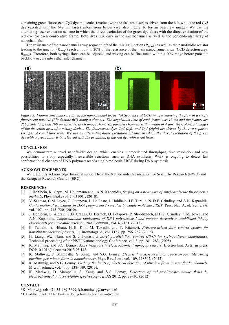
containing green fluorescent Cy3 dye molecules (excited with the 561 nm laser) is driven from the left, while the red Cy5 dye (excited with the 642 nm laser) enters from below (see also Figure 1c for an overview image). We use the alternating-laser excitation scheme in which the direct excitation of the green dye alters with the direct excitation of the red dye for each consecutive frame. Both dyes mix only in the microchannel as well as the perpendicular array of nanochannels.
The resistance of the nanochannel array segment left of the mixing junction (Rarray1) as well as the nanofluidic resistor leading to the junction (Rarray3) each amount to 20% of the resistance of the main nanochannel array (CCD detection area, Rarray2). Therefore, both syringe flows can be adjusted and mixing can be fine-tuned within a 20% range before parasitic backflow occurs into either inlet channel.
Figure 3: Fluorescence microscopy in the nanochannel array. (a) Sequence of CCD images showing the flow of a single fluorescent particle (Rhodamine 6G) along a channel. The acquisition time of each frame was 15 ms and the frames are 256 pixels long and 109 pixels wide. Each image shows six parallel channels with a width of 4 µm. (b) Colorized images of the detection area of a mixing device. The fluorescent dyes Cy3 (left) and Cy5 (right) are driven by the two separate syringes at equal flow rates. We use an alternating-laser excitation scheme, in which the direct excitation of the green dye with a green laser is interleaved with the excitation of the red dye with a red laser. CONCLUSION
We demonstrate a novel nanofluidic design, which enables unprecedented throughput, time resolution and new possibilities to study especially irreversible reactions such as DNA synthesis. Work is ongoing to detect fast conformational changes of DNA polymerases via single-molecule FRET during DNA synthesis. ACKNOWLEDGEMENTS
We gratefully acknowledge financial support from the Netherlands Organization for Scientific Research (NWO) and the European Research Council (ERC). REFERENCES [1] J. Hohlbein, K. Gryte, M. Heilemann and, A.N. Kapanidis, Surfing on a new wave of single-molecule fluorescence
methods, Phys. Biol., vol. 7, 031001, (2010). [2] Y. Santoso, C.M. Joyce, O. Potapova, L. Le Reste, J. Hohlbein, J.P. Torella, N. D.F. Grindley, and A.N. Kapanidis,
Conformational transitions in DNA polymerase I revealed by single-molecule FRET, Proc. Nat. Acad. Sci. USA, vol. 107, pp. 715–720, (2010).
[3] J. Hohlbein, L. Aigrain, T.D. Craggs, O. Bermek, O. Potapova, P. Shoolizadeh, N.D.F. Grindley, C.M. Joyce, and A.N. Kapanidis, Conformational landscapes of DNA polymerase I and mutator derivatives established fidelity checkpoints for nucleotide insertion, Nat. Commun., vol. 4, 2131, (2013).
[4] E. Tamaki, A. Hibara, H.-B. Kim, M. Tokeshi, and T. Kitamori, Pressure-driven flow control system for nanofluidic chemical process, J. Chromatogr. A, vol. 1137, pp. 256–262, (2006).
[5] H. Liang, W.J. Nam, and S. J. Fonash, A novel parallel flow control (PFC) for syringe-driven nanofluidics, Technical proceeding of the NSTI Nanotechnology Conference, vol. 3, pp. 281–283, (2008).
[6] K. Mathwig, and S.G. Lemay, Mass transport in electrochemical nanogap sensors, Electrochim. Acta, in press, DOI:10.1016/j.electacta.2013.05.142.
[7] K. Mathwig, D. Mampallil, S. Kang, and S.G. Lemay, Electrical cross-correlation spectroscopy: Measuring picoliter-per-minute flows in nanochannels, Phys. Rev. Lett., vol. 109, 118302, (2012).
[8] K. Mathwig, and S.G. Lemay, Pushing the limits of electrical detection of ultralow flows in nanofluidic channels, Micromachines, vol. 4, pp. 138–149, (2013).
[9] K. Mathwig, D. Mampallil, S. Kang, and S.G. Lemay, Detection of sub-picoliter-per-minute flows by electrochemical autocorrelation spectroscopy, µTAS 2012, pp. 28–30, (2012).
CONTACT *K. Mathwig, tel: +31-53-489-5699; [email protected] *J. Hohlbein, tel: +31-317-482635; [email protected]
1387