a novel test case design technique using dynamic slicing
TRANSCRIPT

e-Informatica Software Engineering Journal, Volume 2, Issue 1, 2008
A Novel Test Case Design Technique UsingDynamic Slicing of UML Sequence Diagrams
Philip Samuel∗, Rajib Mall∗∗Department of Computer Science and Engineering, Indian Institute of Technology,
Kharagpur(WB),India-721302
[email protected], [email protected]
AbstractWe present a novel methodology for test case generation based on UML sequence dia-grams. We create message dependence graphs (MDG) from UML sequence diagrams.Edge marking dynamic slicing method is applied on MDG to create slices. Based onthe slice created with respect to each predicate on the sequence diagram, we generatetest data. We formulate a test adequacy criterion named slice coverage criterion. Testcases that we generate achieves slice coverage criterion. Our approach achieves slice testcoverage with few test cases. We generate effective test cases for cluster level testing.
1 Introduction
Ever since Weiser [51] introduced program slicing, researchers have shown considerableinterest in this field probably due to its application potential. Slicing is useful in softwaremaintenance and reengineering [15, 35], testing [19, 28, 42], decomposition and integration[23], decompilation [10], program comprehension [38, 20], and debugging [39]. Most of theworks reported on slicing concerns improvements and extensions to algorithms for sliceconstruction [37, 21, 33, 14, 6]. Even though dynamic slicing is identified as a powerfultool for software testing [33, 42], reported work on how dynamic slicing can be used intesting is rare in the literature. In 1993, Kamkar et al. [28] reported how dynamic slicingcan be applied to interprocedural testing. This work is reported in the context of testingprocedural code. To the best of our knowledge, no work is reported in the literature thatdescribes how dynamic slicing can be used for test case generation in the object orientedcontext. In this paper, we propose a method to generate test cases by applying dynamicslicing on UML sequence diagrams.
As originally introduced, slicing (static slicing) considers all possible executions of aprogram. Korel and Laski [32] introduced the concept of dynamic slicing. Dynamic slicingconsiders a particular execution and hence significantly reduces the size of the computedslice. A dynamic slice can be thought of as that part of a program that “affects" the com-putation of a variable of interest during a program execution on a specific program input[33]. A dynamic slice is usually smaller than a static slice, because run-time informationcollected during execution is used to compute the slice. In a later work, Korel has shownthat slicing can be used as a reduction technique on specifications like UML state models
brought to you by COREView metadata, citation and similar papers at core.ac.uk
provided by IO PWr
72 Philip Samuel, Rajib Mall
[34].
The goal of software testing is to ensure quality. Software testing is necessary to producehighly reliable systems, since static verification techniques suffer from several handicaps indetecting all software faults [5]. Hence, testing will be a complementary approach to staticverification techniques to ensure software quality. As software becomes more pervasiveand is used more often to perform critical tasks, it will be required to be of very highquality. Unless more efficient ways to perform effective testing are found, the fraction ofdevelopment costs devoted to testing will increase to unacceptable levels [45].
The most intellectually challenging part of testing is the design of test cases. Test casesare usually generated based on program source code. An alternative approach is to gener-ate test cases from specifications developed using formalisms such as UML models. In thisapproach, test cases are developed during analysis or design stage itself, preferably duringthe low level design stage. Design specifications are an intermediate artifact between re-quirement specification and final code. They preserve the essential information from therequirement, and are the basis of code implementation. Moreover, in component-basedsoftware development, often only the specifications are available and the source code isproprietary. Test case generation from design specifications has the added advantage ofallowing test cases to be available early in the software development cycle, thereby mak-ing test planning more effective. It is therefore desirable to generate test cases from thesoftware design or analysis documents, in addition to test case design using the code.
Now, UML is widely used for object oriented modeling and design. Recently, severalmethods have been proposed to execute UML models [48, 41, 47, 18, 13, 11]. ExecutableUML [41, 47] allows model specifications to be efficiently translated into code. ExecutableUML formalizes requirements and use cases into a set of verifiable diagrams. The modelsare executable and testable and can be translated directly into code by executable UMLmodel compilers. Besides reducing the effort in the coding stage, it also ensures platformindependence and avoids obsolescence. This is so because the code often needs to changewhen ported to new platforms or fine tuning the code on efficiency or reliability consid-erations. It also allows meaningful verification of the models by executing them in a testand debug environment. Our test generation approach can also work on executable UMLmodels.
UML-based automatic test case generation is a practically important and theoreticallychallenging topic. Literature survey indicates, testing based on UML specifications is re-ceiving an increasing attention from researchers in the recent years. In using UML in thesoftware testing process, here we focus primarily on the sequence diagrams where sequencediagrams model dynamic behavior. This is because most of the activities in software test-ing seek to discover defects that arise during the execution of a software system, and thesedefects are generally dynamic (behavioral) in nature [52]. Software testing is fundamentallyconcerned with behavior (what it does), and not structure (what it is) [27]. Customersunderstand software in terms of its behavior, not its structure. Further, UML is used in

A Novel Test Case Design Technique Using Dynamic Slicing of UML Sequence Diagrams 73
the design of object-oriented software, which is primarily event-driven in nature. In suchcases, the concept of a main program is minimized and there is no clearly defined integra-tion structure. Thus there is no decomposition tree to impose the question of integrationtesting order of objects. Hence, it is no longer natural to focus on structural testing orders.Whereas, it is important to identify in what sequence objects interact to achieve a commonbehavior. In this context, UML sequence diagrams forms an useful means by which we cangenerate effective test cases for cluster level testing.
In this paper, we concentrate on UML sequence diagrams to automatically generate testcases. This paper is organized as follows: A brief discussion on sequence diagrams is givenin the next section. In Section 3 we discuss few basic concepts. Section 4 describes ourmethodology to generate test cases from sequence diagrams and explains our methodologywith an example. Section 5 discusses an implementation of our test methodology. Relatedresearch in the area of UML based testing is discussed in the Section 6 and conclusions aregiven in Section 7.
2 UML Sequence Diagrams
Noteresponse()
message1(argu)startmessage()
Life line
Activation
:object1 :object2 :object3
alt
asynchronous message4()
Interaction Operator
message2()[x<25]message3()
[y>10]
[else]
Interaction Constraint
message5() SeperatorInteraction operand
Combined fragment(alternative)
Condition
Figure 1: A Sequence Diagram Showing Various Notations
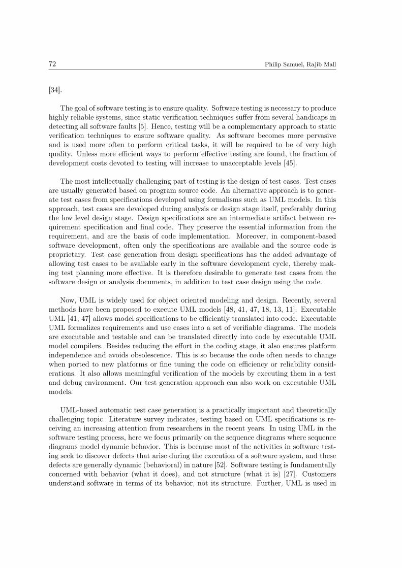
UML Sequence diagrams capture time dependent (temporal) sequences of interactionsbetween objects. They show the chronological sequence of the messages, their names andresponses and their possible arguments. A sequence diagram has two dimensions: the
74 Philip Samuel, Rajib Mall
vertical dimension represents time, and the horizontal dimension represents different in-stances. Normally time proceeds from top to bottom [44]. Message sequence descriptionsare provided in sequence diagrams to bring forth meanings of the messages passed betweenobjects. Sequence diagrams describe interactions among software components, and thusare considered to be a good source for cluster level testing. In UML, a message is a requestfor a service from one UML actor to another, these is typically implemented as methodcalls. We assume that each sequence diagram represents a complete trace of messagesduring the execution of a user-level operation.
An example of a UML sequence diagram is shown in Fig. 1. The vertical dashed linein the diagram is called a lifeline. A lifeline represents the existence of the correspondingobject instance at a particular time. Arrows between the lifelines denote communicationbetween object instances using messages. A message can be a request to the receiver objectto perform an operation(of the receiver). A synchronous message is shown with a filledarrowhead at the end of a solid line. An asynchronous message is depicted with an openarrowhead at the end of a solid line. Return messages are usually implied. We can ex-plicitly show return messages using an open stick arrowhead with a dashed line as shownin Fig. 1. An object symbol shown with a rectangle is drawn at the head of the lifeline.An activation (focus of control) shows the period during which an instance is performing aprocedure. The procedure being performed may be labeled in text next to the activationsymbol or in the margin.
UML 2.0 also allows an element called note, for adding additional information to thesequence diagram. Notes are shown with dog-eared rectangle symbols linked to object life-line through a dashed line as shown in Fig.1. Notes are convenient to include pseudocode,constraints, pre-conditions, post-conditions, text annotations etc. in sequence diagram.However, in our approach we restrict the notes to contain only executable statements.Messages in the sequence diagram are chronologically ordered. So we have numbered thembased on their timestamps. Further, we have numbered the notes in an arbitrary manner.
In UML 2.0, a set of interactions can be framed together and can be reused at otherlocations. Different interaction fragments can be combined to form a combined fragment. Acombined interaction fragment defines an expression of interaction fragments. A combinedinteraction fragment is defined by an interaction operator and corresponding interactionoperands. Through the use of combined fragments, the user will be able to describe anumber of traces in a compact and concise manner. A combined fragment with an operatoralt (for alternative) is shown in Fig. 1.
3 Basic Concepts
In this section, we discuss a few basic concepts that are useful to understand the rest ofthis paper.

A Novel Test Case Design Technique Using Dynamic Slicing of UML Sequence Diagrams 75
Class, Cluster and System Level Testing: In object oriented systems, generally testingis done at different levels of abstraction: class level, cluster level and system level[9, 50, 30].Class level testing tests the code for each operation supported by a class as well as all pos-sible method interactions within the class. Class level testing also includes testing themethods in each of the states that a corresponding object may assume. At cluster leveltesting, the interactions among cooperating classes are tested. This is similar to integrationtesting. The system level testing is carried out on all the clusters making up the completesystem.
Executable UML: Executable UML [41, 47] allows model specifications to be efficientlytranslated into code. Executable UML can formalize requirements and use cases into a richset of verifiable diagrams. The models are executable and testable and can be translateddirectly into code by executable UML model compilers. The benefits of this approach gowell beyond simply reducing or eliminating the coding stage; it ensures platform indepen-dence, avoids obsolescence (programming languages may change, the model doesn’t) andallows full verification of the models by executing them in a test and debug environment.
Test Case: A test case is the triplet (I,D,O) where I is the state of the system at whichthe test data is input, D is the test data input to the system, and O is the expected outputof the system [2, 40, 43]. The output produced by the execution of the software with aparticular test case provides a specification of the actual software behavior.
4 Dynamic Slicing based Test Case Generation from SequenceDiagrams
In this section we describe our proposed methodology for automatic test case generationfrom UML sequence diagrams using dynamic slicing. We first define a few terms and therelevant test coverage criteria.
4.1 Definitions
The following definitions would be used in the description of our methodology.
Message Dependency Graph (MDG): We define MDG as a directed graph with (N,E),where N is a set of nodes and E is a set of edges. MDG shows the dependency of a givennode on the others. Here a node represents either a message or a note in the sequencediagram and edges represent either control or data dependency among nodes. Here we haveassumed that notes are attached to objects and the statements on the notes are executedwhen its corresponding lifeline is activated. MDG does not distinguish between control ordata dependence edges. It does however distinguish between stable and unstable edges.Definitions of stable and unstable edges are given subsequently. The induced subgraph ofMDG of the sequence diagram in Fig.2 on the Node Set(3,4,5,6,7,8,9,10,11,12,13) is shown

76 Philip Samuel, Rajib Mall
in Fig.3. of Subsection 4.7.
Slicing Criteria: Slices are constructed based on a slicing criterion. Weiser’s slicing crite-rion [51] consisted of a set of variables of interest and a point of interest within the originalprogram. Statements which cannot affect the values of variables at a point of interest inthe program are removed to form the slice. In our case, the slicing criterion (m, V) specifiesthe location (identity) of a message m in its corresponding MDG and V is a set of variablesthat are used by the conditional predicate on the message at m.
Dynamic Slice: A dynamic slice of a sequence diagram is defined with respect to its cor-responding MDG. Consider a predicate in MDG on a message m in a sequence diagram.A dynamic slice is the induced subgraph of MDG, induced by the set of nodes in MDGthat affect a predicate at m for a given execution. We call this slice as a dynamic slice ofsequence diagram. Those nodes of MDG that do not affect the predicate at m are removedto form the slice, for the slicing criterion (m,V).
UseVar(x): It is the set of all nodes in MDG that uses the value of variable x. For ex-ample, in the expression (n = x ∗ y) there is a use of the value of the variable x.
AllotVar(x): It is the set of all nodes in MDG that defines the variable x. In addition,consider a conditional guard specifies a condition in a message using variable x. If x is usedto specify another condition in another message, such conditional guards are also treated asmembers of AllotVar(x). We use the term allotment to indicate that a variable x is eitherdefined or if x is used to specify guards in the rest of paper. For example, consider nodes 4and 8 in MDG as shown in Fig. 3. These nodes correspond to messages [y < 50]msg4 and[y > 120]msg8 respectively in Fig. 2. For a particular input value for the variable y, onlyone of these messages will take place. Hence, both nodes 4 and 8 are treated as membersof AllotVar(y). A use of y will require only one of the AllotVar(y), not both.
Dependence Edge: If node i is a member of usevar(x) and a node j is a member ofAllotVar(x), then there is a directed edge from node i to node j, this edge is also called adependence edge.
Dependency Path: A dependency path F from some node vi, to a node vk is a sequenceof nodes and edges in MDG from vi to vk.
Unstable Edge: Let M,Mi,Mj be three nodes in MDG. An outgoing dependence edge(M,Mi) in MDG is said to be unstable if there exists an outgoing dependence edge (M,Mj)with Mi not equal to Mj such that the statements Mi and Mj both are members of Al-lotVar(x). For example, in Fig.2, the messages [y < 50]msg4 and [y > 120]msg8 will formunstable edges with respect to the message [a + y > 20]msg11. These edges correspondsto (4,11) and (8,11) respectively in the MDG shown in Fig.3.

A Novel Test Case Design Technique Using Dynamic Slicing of UML Sequence Diagrams 77
Stable Edge: An edge in a dependency graph is said to be stable, if it is not an unstableedge.
Slice Condition: Consider a slice S of a sequence diagram for the slicing criterion (m,V).The slice condition of the slice S is the conjunction of all the individual predicates presentin the dynamic slice for a given execution.
Slice Domain: The slice domain of slice S is the set of all input data values for which theslice condition of S is satisfied.
Boundary: A slice domain is surrounded by a boundary. A boundary is a set of datapoints. A boundary might consist of several segments and each segment of the boundaryis called a border [17]. Each border is determined by a single simple predicate in the slicecondition. A border crossing occurs for some input where the conditional predicate changesits Boolean value from true to false or vice versa.
4.2 Test Coverage
A software test data adequacy criterion (or coverage criterion) is used to find out whethera set of test cases is sufficient, or "adequate," for testing a given software. Some of therelevant test criteria are introduced in this section.
4.2.1 Slice Coverage Criterion
Several test coverage criteria such as message path criteria, full predicate coverage etc., havebeen proposed in the literature[2]. Several other criteria such as slice coverage criterioncan easily be formulated based on these criteria. We extend slice coverage criterion frompath based criteria. Slice criteria is defined with respect to a dependency graph. We defineslice coverage criterion for sequence diagram as follows: Consider a test set T and an MDGcorresponding to a sequence diagram SD. In order to satisfy the slice coverage criterion, itis required that T must cause all the dependency paths in MDG for each slice to be takenat least once. Slice coverage ensures that all the dependency paths of an MDG (MessageDependency Graph) are covered.
4.2.2 Full Predicate Coverage
Full predicate coverage criterion requires that each clause should be tested independently[43].In other words, each clause in each predicate on every message must independently affectthe outcome of the predicate. Given a test set T and sequence diagram SD, T must causeeach clause in every predicate on each message in SD to take on the values of TRUE andFALSE while all other clauses in the predicate have values such that the value of the pred-icate will always be the same as the clause being tested. This ensures that each clause ina condition is separately tested.

78 Philip Samuel, Rajib Mall
4.2.3 Boundary Testing Criterion
Testers have frequently observed that domain boundaries are particularly fault-prone andshould therefore be carefully checked[25]. Boundary testing criterion is applicable wheneverthe test input domain is subdivided into subdomains by decisions (conditional predicates).Let us select an arbitrary border for each predicate p. We assume that the conditionalpredicates on the sequence diagram are relational expressions (inequalities). That is, allconditional predicates are of the following form: E1opE2, where E1andE2 are arithmeticexpressions, and op is one of {<,≤, >,≥}. Jeng and Weyuker[25] have reported that aninequality border can be adequately tested by using only two points of test input domain,one named ON point and the other named OFF point. The ON point can be anywhereon the given border. It does not even have to lie exactly on the given border. All that isnecessary is that it satisfies all the conditions associated with the border. The requirementfor the OFF point is that it be as close to the ON point as possible, but it should lie outsidethe border.
The boundary testing criterion can now be defined as follows: The boundary testingcriterion is satisfied for inequality borders if each selected inequality border b is tested bytwo points (ON-OFF) of test input domain such that, if for one of the points the outcomeof a selected predicate q is true, then for the other point the outcome of q is false. Alsothe points should satisfy the slice condition associated with b and the points should be asclose as possible to each other [17].
Definitions of boundary testing criteria for equality and non-equality borders are definedin [25, 17]. For conciseness, we do not consider them here. However they can easily beconsidered in our approach. We use boundary testing as an extension of slice coveragecriterion. The number of test cases to be generated for achieving slice coverage criterioncan be very large if we use a random approach. We reduce this by using boundary testingalong with slice coverage. For example consider a the predicate (n < 400) shown in Fig.2.In the example section we have shown two test data that can be used to test it and they are[21,20] and [21,19] where, the test data has the values of [x,y] for the predicate (n < 400).The slice condition consists of (x > 20), (y < 50), (n = x∗y) and the test data is generatedsubject to slice condition. Instead of generating a set of test cases randomly and selectingthe test cases from this set that satisfies this slice condition, we generate two test casesbased on a simple predicate using boundary testing.
4.3 Overview of Our Approach
In our approach, the first step is to select a conditional predicate on the sequence diagram.The order in which we select predicates is the chronological order of messages appearing in asequence diagram. For each message in the sequence diagram, there will be a correspondingnode in the MDG. For each conditional predicate, we create the dynamic slice for the slicingcriteria (m,V) and with respect to each slice we generate test data. The generated testdata for each predicate corresponds to the true or false values of the conditional predicate

A Novel Test Case Design Technique Using Dynamic Slicing of UML Sequence Diagrams 79
and these values are generated subject to the slice condition. This helps to achieve slicecoverage. The different steps of our approach are elaborated in the following subsections.
4.4 Dynamic Slice of Sequence Diagrams
In our approach, a dynamic slice of a sequence diagram is constructed from its correspond-ing MDG (Message dependency graph). An MDG is created statically and it needs to becreated only once. For each message in the sequence diagram, there will be a correspond-ing node in the MDG. From MDG, we create the dynamic slice corresponding to eachconditional predicate, for the slicing criteria (m,V). For creating dynamic slices we usean edge marking method. Edge marking methods are reported in [26, 42] for generatingdynamic slices in the context of procedural programs. Their edge marking methods usesprogram dependence graph. We generate a message dependence graph from UML sequencediagram and apply the edge marking technique on it. Edge marking algorithm is based onmarking and unmarking the unstable edges appropriately as and when dependencies ariseand cease at run time. After an execution of the node x at run-time, an unstable edge(x,y)is marked if the node x uses the value of the variable v at node y and node y is a memberof AllotVar(v). A marked unstable edge(x,y) is unmarked after an execution of a node zif the nodes y and z are in AllotVar(v), and the value of v computed at node y does notaffect the present value of v at node z. In our approach we generate test data that satisfiesall constraints corresponding to a slice.
Before execution of a message sequence M, the type of each of its edges in MDG is ap-propriately recorded as either stable or unstable. The dependence associated with a stableedge exists at every point of execution. The dependence associated with an unstable edgekeeps on changing with the execution of the node. We mark an unstable edge when its asso-ciated dependence exists, and unmark when its associated dependence ceases to exist. Eachstable edge is marked and each unstable edge is unmarked at the time of construction of theMDG. We mark and unmark edges during the execution of the message sequences, as andwhen a dependencies arise or cease, and a stable edge is never unmarked. Let dslice(n)denote the dynamic slice with respect to the most recent execution of the node n. Let(n, x1), (n, x2), . . . , (n, xn) be all the marked outgoing dependence edges of n in the updatedMDG after an execution of the node n. It is clear that the dynamic slice with respect tothe present execution of the node is dslice(n) = x1, x2, . . . , xn∪dslice(x1)∪· · ·∪dslice(xn).
We now present the edge marking dynamic slicing algorithm for sequence diagrams inpseudocode form. Subsequently this method is explained using an example.
Edge Marking Dynamic Slicing Algorithm for Sequence Diagrams
• Do before execution of the message sequence:-
– Unmark all the unstable edges.
– Set dslice(n) = NULL for every node n of the MDG.

80 Philip Samuel, Rajib Mall
• For each node n of the message sequence Do
– For every variable used at n, mark the unstable edge corresponding to its mostrecent allotment. (Suppose there is a predicate x > 50 which is true for the givenexecution step and inputs then the edge to that predicate is marked. If the predicateis false then it remains unmarked.)
– Update dslice(n).
– If n is a member of AllotVar(x) and n is not a UseVar(x) node, then do the following:-
∗ Unmark every marked unstable edge (n1, n2) with n1 ∈ UseV ar(x) and n2 isa node that does not affect the present allotment of the variable var. Hence,the marked unstable edge (n1, n2) representing the dependence of node n1 onnode n2 in the previous execution of node n1 will not continue to represent thesame dependence in the next execution of node n1.
For example, let x = 30, y = 45, p = 55, q = 40, a = 10 be a data set for the diagramgiven in Fig. 2. For the slicing criteria (11,y), initially let edges (11,4) and (11,8) areunmarked unstable edges as seen in Fig. 3. During the execution of node 11, for thegiven data set, we mark the unstable edge (11,4) whereas the unstable edge (11,8) remainsunmarked as the value of y at present is 45. Hence the dynamic slice of node 11 for theslicing criteria (11,y) is 4∪ dslice6 and do not include 8. Let at some other execution, thedata set is x = 30, y = 55, p = 45, q = 40, a = 10. In this case the dynamic slice of node11 for the slicing criteria (11,y) is 8 ∪ dslice6 and do not include 4.
4.5 Generation of Predicate Function
Consider an initial set of data I0 that is randomly generated for the variables that affecta predicate p in a slice S. As already mentioned in our approach, we compute two pointsnamed ON and OFF for a given border satisfying the boundary testing criterion. Wetransform the relational expressions of the predicates to a function F (Predicate Function).If the predicate p is of the form (E1 op E2), where E1 and E2 are arithmetic expressions,and op is a relational operator, then F = (E1 - E2) or (E2 - E1) depending on whicheveris positive for the data I0. Next we successively modify the input data I0 such that thefunction F decreases and finally turns negative. When F turns negative, it corresponds tothe alternation of the outcome of the predicate. Hence as a result of the above predicatetransformation, the change in the outcome of predicate p now corresponds to the problemof minimization of the function F. This minimization can be achieved through repeatedmodification of input data value.
4.6 Test Data Generation
The basic search procedure we use for finding the minimum of the predicate function Fis the alternating variable method[31, 17] which consists of minimizing F with respect toeach input variable in turn. Each input data variable xi is increased/decreased in steps of

A Novel Test Case Design Technique Using Dynamic Slicing of UML Sequence Diagrams 81
Uxi, while keeping all the other data variables constant. Here Uxi refers to a unit step ofthe variable xi. The unit step depends on the data type being considered. For example,the unit step is 1 for integer values. The method works with many other types of data suchas float, double, array, pointer etc. However the method may not work when the variableassumes only a discrete set of values. Each predicate in the slice can be considered to be aconstraint. If any of the constraint is not satisfied in the slice, for some input data value,we say that a constraint violation has taken place. We compute the value of F when eachinput data is modified by Uxi. If the function F has decreased on the modified data, andconstraint violation has not occurred, then the given data variable and the appropriatedirection is selected for minimizing F further. Here appropriate direction refers to whetherwe increase or decrease the data variable xi. We start searching for a minimum with aninput variable while keeping all the other input variables constant until the solution isfound (the predicate function becomes negative) or the positive minimum of the predicatefunction is located. In the latter case, the search continues from this minimum with thenext input variable.
4.7 An Example
Consider an example sequence diagram as shown in Fig.2. We have selected this example asit demonstrates the concepts in our approach. We illustrate our methodology by explainingthe test data generation for the predicate (n < 400) shown in Fig.2. Its corresponding MDGis shown in Fig.3. Let the slicing criterion be (6,n). For this slicing criterion, the slicecontains of the set of nodes that corresponds to predicates (x > 20), (y < 50), (n = x ∗ y).The function F will be the expression (n− 400). Let I0 be the initial data: [25,40] where(x = 25, y = 40). The condition (n < 400) is false for I0 as (1000 < 400). The function Fwill be the expression (n− 400) and F(I0) = 600. We should minimize F, in order to alterthe boolean outcome of predicate (n < 400), which is false initially.
First we decrease the value of data x in steps. In the first step, we take x =24 and thevalue of F is calculated as 560 for [x,y] = [24,40]. Observe that the function F reduces byreducing x. Therefore in the next step, the size of the step is doubled and hence the valueof variable x is decreased by 2. As we minimize F further in several iterations, we finallyarrive at two data points With [x,y] = [21,20], F is positive and the condition (n < 400) isstill false. So we take two data sets Iin as [x,y] = [21,20] that makes F positive (or zero)and another data set Iout as [x,y] = [21,19] that makes F negative.
The test cases we generate for the predicate (n < 400) are (object1, [21,19], object2) and(object1, [21,20], object1) correspond to different truth values of the predicate (n < 400).Here test cases has the form (sender object, [test data], receiver object). Test data hasthe values of [x,y] for the predicate (n < 400). These test cases are generated satisfyingthe slice condition of the slice. With our proposed method we generate test cases for eachsuch conditional predicates on the sequence diagram.

82 Philip Samuel, Rajib Mall
{n=x*y} 12
{r=p+q} 13
object1 object3
[x>20]msg1msg2
[p−q>=0]msg3[y<50]msg4
[p>=20 and q<50]msg5
[n<400]msg6[p<=120]msg7
[y>120]msg8
[r<150]msg9
[p>40]msg10
[a+y>20]msg11
object2
Figure 2: An Example Sequence Diagram
5 An Implementation
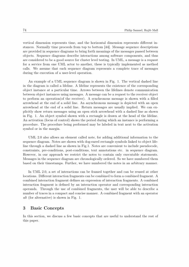
To the best of our knowledge, no full-fledged ready made tool exists that are publiclyavailable to execute UML models. Hence, for generating dynamic slices in our experimen-tation, we have simulated the executions. We made a prototype tool that implements ourmethod. Fig. 4 shows the important classes that we used to generate test cases fromsequence diagram in our implementation. SliceGenerator class creates the message depen-dency graph. It makes the sets defSet and useSet for each variable in the sequence diagram.It forms slices based on the slicing criteria for each of the messages in the sequence diagram.SliceRecord class keeps a record of slices.
DocumentParser class parses the XML file corresponding to a UML sequence diagram.We used the Document Object Model (DOM) API that comes with the standard editionof the Java platform, for parsing XML files. The package org.w3c.dom.*, provides theinterfaces for the DOM. The DOM parser begins by creating a hierarchical object modelof the input XML document. This object model is then made available to the applicationfor it to access the information it contains in a random access fashion. This allows anapplication to process only the data of interest and ignore the rest of the document.
XmlBoundary is the class of the program from which the execution starts. It accepts anXML file of sequence diagram from a user. Then it extracts the parent tag of the XML fileand passes the tag (called head) to the TestCaseController class. TestCaseController classcoordinates the different activities of the program. TestCaseBoundary class is responsiblefor displaying the list of test cases for a collaboration diagram. The source and destination

A Novel Test Case Design Technique Using Dynamic Slicing of UML Sequence Diagrams 83
Stable Edge
Unstable Edge
3
4
6
7
11
13
10
9
8
12
5
Figure 3: The Induced Subgraph of Dependency Graph of the Sequence Diagram in Fig.2 on theNode Set(3,4,5,6,7,8,9,10,11,12,13)
objects as well as the slice condition is printed along with test data.
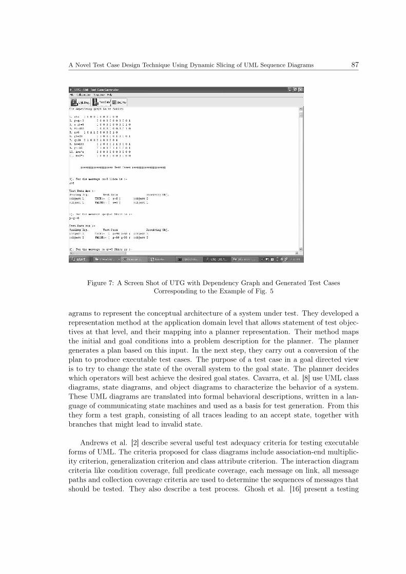
In our prototype implementation, we have considered only integer and Boolean variablesas part of the conditional expression in sequence diagrams. Other data types however caneasily be considered. Further, for the prototype implementation we have assumed that thenecessary constraints are available in notes instead of class/object diagrams. Extractingdata types of attributes, or constraints from class/object diagrams for our implementationcan be easily done. The GUI was developed using the swing component of Java. A GUIscreen along with a sample sequence diagram is shown in Fig. 5. The GUI gives theflexibility to view the sequence diagram, its XML representation and the generated testcases. Fig. 6 shows the UTG display of the XML file of example given in Fig. 5. Thecorresponding test cases generated are shown in Fig. 7. Our tool allows storing the testcases as text files for later processing.
We have implemented our method for generating test cases automatically from UMLsequence diagrams in a prototype tool named UTG. Here, UTG stands for UML behavioralTest case Generator. UTG has been implemented using Java and can easily integrate withany UML CASE tools like MagicDraw UML [24] that supports XML (Extensible MarkupLanguage) format. Since UTG takes UML models in XML format as input, UTG isindependent of any specific CASE tool. We have used the tool with several UML designsand the tool was found effective in generating test cases. The generated test cases werefound to achieve the desired coverage.
84 Philip Samuel, Rajib Mall
GeneratorSlice TestData
Record
TestCaseController
XmlBoundary
TestCaseBoundary
DocumentParser
SliceRecord
Stack
Figure 4: Class Diagram of UTG for Generating Test Cases From Sequence Diagrams
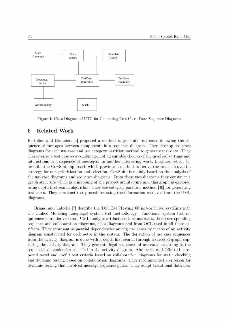
6 Related Work
Bertolino and Basanieri [4] proposed a method to generate test cases following the se-quence of messages between components in a sequence diagram. They develop sequencediagrams for each use case and use category partition method to generate test data. Theycharacterize a test case as a combination of all suitable choices of the involved settings andinteractions in a sequence of messages. In another interesting work, Basanieri, et al. [3]describe the CowSuite approach which provides a method to derive the test suites and astrategy for test prioritization and selection. CowSuite is mainly based on the analysis ofthe use case diagrams and sequence diagrams. From these two diagrams they construct agraph structure which is a mapping of the project architecture and this graph is exploredusing depth-first search algorithm. They use category partition method [46] for generatingtest cases. They construct test procedures using the information retrieved from the UMLdiagrams.
Briand and Labiche [7] describe the TOTEM (Testing Object-orienTed systEms withthe Unified Modeling Language) system test methodology. Functional system test re-quirements are derived from UML analysis artifacts such as use cases, their correspondingsequence and collaboration diagrams, class diagrams and from OCL used in all these ar-tifacts. They represent sequential dependencies among use cases by means of an activitydiagram constructed for each actor in the system. The derivation of use case sequencesfrom the activity diagram is done with a depth first search through a directed graph cap-turing the activity diagram. They generate legal sequences of use cases according to thesequential dependencies specified in the activity diagram. Abdurazik and Offutt [1] pro-posed novel and useful test criteria based on collaboration diagrams for static checkingand dynamic testing based on collaboration diagrams. They recommended a criterion fordynamic testing that involved message sequence paths. They adapt traditional data flow

A Novel Test Case Design Technique Using Dynamic Slicing of UML Sequence Diagrams 85
Figure 5: The GUI Screen of UTG With an Example Sequence Diagram
coverage criteria (eg. all definition - uses) in the context of UML collaboration diagrams.
Linzhang, et al. [36] proposed a gray-box testing method using UML activity diagrams.They propose an algorithm to generate test scenarios from activity diagrams. The informa-tion regarding input/output sequence, parameters, the constraint conditions and expectedobject method sequence is extracted from each test scenario. They recommend applyingcategory-partition method to generate possible values of all the input/output parametersto find the inconsistency between the implementation and the design.
Among all UML diagrams, test case generation from state chart diagram has possiblyreceived maximum attention from researchers [8, 22, 29, 30, 43, 49]. Offutt and Abdurazik[43] developed an interesting technique for generating test cases from UML state diagramswhich is intended to help perform class-level testing. Their method takes a state transi-tion table as input, and generates test cases for the full predicate coverage criterion. Itprocesses each outgoing transition of each source state, generates a test case that makesthe transition taken, and then generates test cases that make the transition untaken. Atest case is designed corresponding to each variable in a transition predicate. To avoidredundant test case value assignments, those variables that have already been assignedvalues are not considered in the subsequent test case value assignment process. After alltest case values are generated, an additional algorithm is run on the test cases to identify

86 Philip Samuel, Rajib Mall
Figure 6: A Screen Shot of UTG with a Portion of the XML File Corresponding to example inFig. 5
and remove redundant test cases. Kansomkeat, et al. [29] have proposed an alternatemethod for generating test sequences using UML state chart diagrams. They transformthe state chart diagram into an intermediate diagram called Testing Flow Graph (TFG)which is used to generate test sequences. TFG is a flattened hierarchy structure of states.The testing criterion they proposed is the coverage of states and transitions of TFG.
Kim, Y.G et al. [30] proposed a method for generating test cases for class testing usingUML state chart diagrams. They transform state charts to extended finite state machines(EFSMs) to derive test cases. The hierarchical and concurrent structure of states is flat-tened and broadcast communications are eliminated in the resulting EFSMs. Next dataflows are identified by transforming EFSMs into flow graphs to which conventional dataflow analysis techniques are applied. Hartmann et al. [22] augment the UML descriptionwith specific notations to create a design-based testing environment. The developers firstdefine the dynamic behavior of each system component using a state diagram. The in-teractions between components are then specified by annotating the state diagrams, andthe resulting global FSM that corresponds to the integrated system behavior is used togenerate the tests.
Scheetz et al. [49] developed an approach for generating system (black box) test casesusing an AI (Artificial Intelligence) planner. They used UML class diagrams and state di-
A Novel Test Case Design Technique Using Dynamic Slicing of UML Sequence Diagrams 87
Figure 7: A Screen Shot of UTG with Dependency Graph and Generated Test CasesCorresponding to the Example of Fig. 5
agrams to represent the conceptual architecture of a system under test. They developed arepresentation method at the application domain level that allows statement of test objec-tives at that level, and their mapping into a planner representation. Their method mapsthe initial and goal conditions into a problem description for the planner. The plannergenerates a plan based on this input. In the next step, they carry out a conversion of theplan to produce executable test cases. The purpose of a test case in a goal directed viewis to try to change the state of the overall system to the goal state. The planner decideswhich operators will best achieve the desired goal states. Cavarra, et al. [8] use UML classdiagrams, state diagrams, and object diagrams to characterize the behavior of a system.These UML diagrams are translated into formal behavioral descriptions, written in a lan-guage of communicating state machines and used as a basis for test generation. From thisthey form a test graph, consisting of all traces leading to an accept state, together withbranches that might lead to invalid state.
Andrews et al. [2] describe several useful test adequacy criteria for testing executableforms of UML. The criteria proposed for class diagrams include association-end multiplic-ity criterion, generalization criterion and class attribute criterion. The interaction diagramcriteria like condition coverage, full predicate coverage, each message on link, all messagepaths and collection coverage criteria are used to determine the sequences of messages thatshould be tested. They also describe a test process. Ghosh et al. [16] present a testing

88 Philip Samuel, Rajib Mall
method in which executable forms of Unified Modeling Language (UML) models are tested.In systematic design testing, executable models of behaviors are tested using inputs thatexercise scenarios. This can help reveal flaws in designs before they are implemented incode. Their method incorporates the use of test adequacy criteria based on UML classdiagrams and interaction diagrams. Class diagram criteria are used to determine the ob-ject configurations on which tests are run, while interaction diagram criteria are used todetermine the sequences of messages that should be tested. These criteria can be used todefine test objectives for UML designs. Engels et al. [12] discuss how consistency amongdifferent UML models can be tested. They propose dynamic meta modeling rules as anotation for the consistency conditions and provide the concept for an automated testingenvironment using these rules.
In contrast with the above discussed approaches we generate actual test cases from se-quence diagrams. Our approach can work on executable forms of UML design specificationsand is meant for cluster level testing where object interactions are tested. Correspondingto each conditional predicate on the sequence diagram, we construct dynamic slice fromits MDG and with respect to the slice we generate test data. Our test data generationscheme is automatic.
Kamkar et al. [28] explains how interprocedural dynamic slicing can be used to increasethe reliability and precision of interprocedural data flow testing. Harman and Danicic [19]presents an interesting work that illustrates how slicing will remove statements which donot affect a program variable at a location thereby simplifying the process of testing andanalysis. They also provide a program transformation algorithm to make a program ro-bust. Slicing has been used as a reduction technique on specifications like state models[34]. Anyhow this work [34] do not provide a scheme for test generation
Korel [31] generated test data based on actual execution of a program under test. Heused function minimization methods and dynamic data flow analysis. If during a programrun an undesirable execution flow is observed (e.g., the "actual" path does not correspondto the selected control path), then function minimization search algorithms are used toautomatically locate the values of input variables for which the selected path is traversed.This helps in achieving path coverage. In addition, dynamic data flow analysis is used todetermine those input variables that are responsible for the undesirable program behavior,leading to significant speedup of the search process. Hajnal et al. [17] extended the workdone by Korel [31]. They reported the use of boundary testing that requires the testingof one border only along a selected path. The test input domain may be surrounded by aboundary and each segment of the boundary is called a border. The task to generate twotest data points considering only one border for each path, is much easier. Their testingstrategy can also handle compound predicates. Jeng and Weyuker [25] have reported thatan inequality border can be tested by only two points of test input domain, one namedON point and another named OFF point. For borders in a discrete space containing nopoints lying exactly on the border, their strategy allows the ON point to be chosen frombeneath the border as long as the distance between the ON and OFF points is minimized.

A Novel Test Case Design Technique Using Dynamic Slicing of UML Sequence Diagrams 89
These works [28, 19, 31, 17, 25] discussed above have focused on unit testing of proceduralprograms.
7 Conclusion
We have presented a novel method to generate test cases by dynamic slicing UML sequencediagrams. Our approach is meant for cluster level testing where object interactions aretested. Our approach automatically generates test data, which can be used by a tool tocarry out automatic testing of a program. Generation of MDG is the only static part in ourapproach. We identify the conditional predicates associated with messages in a sequencediagram and create dynamic slice with respect to each conditional predicate. We generatetest data with respect to each constructed slice and the test data is generated satisfyingslice condition. We have formulated a test adequacy criterion named slice coverage crite-rion. We have implemented our methodology to develop a prototype tool which was foundeffective in generating test cases. The test cases generated can also be used for confor-mance testing of the actual software where the implementation is tested to check whetherit conforms to the design. The slicing approach was found to be especially advantageouswhen the number of messages in the sequence diagram is large. We need to consider onlythe slices for finding test cases instead of having to look at the whole sequence diagram.If the sequence diagram is large it becomes very complex and difficult to find test casesmanually. If we know where to look for errors it becomes a great simplification and savesa lot of time and resources. The slices help to achieve this simplification. The generatedtest cases were found to achieve slice coverage.
Acknowledgements
The authors would like to thank Pratyush Kanth and Sandeep Sahoo for implementingour approach presented in this paper.
References
[1] A. Abdurazik and J. Offutt. Using UML collaboration diagrams for static checking and testgeneration. In Proceedings of the 3rd International Conference on the UML, Lecture Notes inComputer Science, volume 1939, pages 383 – 395, York, U.K., October 2000. Springer-VerlagGmbH.
[2] A. Andrews, R. France, S. Ghosh, and G. Craig. Test adequacy criteria for UML designmodels. Software Testing Verification and Reliability, 13:97 – 127, 2003.
[3] F. Basanieri, A. Bertolino, and E. Marchetti. The cow suit approach to planning and derivingtest suites in UML projects. In Proceedings of the Fifth International Conference on theUML, LNCS, volume 2460, page 383–397, Dresden, Germany, October 2002. Springer-VerlagGmbH.
[4] A. Bertolino and F. Basanieri. A practical approach to UML-based derivation of integrationtests. In Proceedings of the 4th International Software Quality Week Europe and InternationalInternet Quality Week Europe, Brussels, Belgium, 2000. QWE.

90 Philip Samuel, Rajib Mall
[5] R. V. Binder. Testing object-oriented software: a survey. Software Testing Verification andReliability, 6(3/4):125 – 252, 1996.
[6] D. Binkley and K. Gallagher. Program Slicing, volume 43 of Advances in Computers. AcademicPress, 1996.
[7] L. Briand and Y. Labiche. A UML-based approach to system testing. In Proceedings of the4th International Conference on the UML, LNCS, volume 2185, pages 194 – 208, Toronto,Canada, January 2001. Springer-Verlag GmbH.
[8] A. Cavarra, C. Crichton, and J. Davies. A method for the automatic generation of test suitesfrom object models. Information and Software Technology, 46(5):309 – 314, 2004.
[9] H. Y. Chen, T. H. Tse, and T. Y. Chen. Taccle: a methodology for object-oriented soft-ware testing at the class and cluster levels. ACM Transactions on Software Engineering andMethodology, 10(4):56–109, January 2001.
[10] C. Cifuentes and A. Fraboulet. Intraprocedural static slicing of binary executables. In IEEEInternational Conference on Software Maintenance (ICSM’97), page 188 – 195. IEEE Com-puter Society Press, Los Alamitos, USA, 1997.
[11] T. T. Dinh-Trong. Rules for generating code from UML collaboration diagrams and activitydiagrams. Master’s thesis, Colorado State University, Fort Collins, Colorado, 2003.
[12] G. Engels, J. Hausmann, R. Heckel, and S. Sauer. Testing the consistency of dynamic UMLdiagrams. In Proceedings of the Sixth International Conference on Integrated Design andProcess Technology(IPDT), USA, 2002. Society for Design and Process Science.
[13] G. Engels, R. Hucking, S. Sauer, and A. Wagner. UML collaboration diagrams and theirtransformations to java. In Proceedings of the 2nd International Conference on the UML,LNCS, volume 1723, pages 473 – 488, Berlin / Heidelberg, October 1999. Springer.
[14] F.Tip. A survey of program slicing techniques. Journal of Programming Languages, 3(3):121– 189, June 1995.
[15] K. B. Gallagher and J. R. Lyle. Using program slicing in software maintenance. IEEETransactions on Software Engineering, 17(8):751 – 761, August 1991.
[16] S. Ghosh, R. France, C. Braganza, N. Kawane, A. Andrews, and O. Pilskalns. Test adequacyassessment for UML design model testing. In Proceedings of the 14th International Symposiumon Software Reliability Engineering (ISSRE’03), pages 332 – 343. IEEE Computer Society,November 2003.
[17] A. Hajnal and I. Forgacs. An applicable test data generation algorithm for domain errors. InACM SIGSOFT Software Engineering Notes, Proceedings of ACM SIGSOFT InternationalSymposium on Software Testing and Analysis, volume 23, 1998.
[18] D. Harel and E. Gery. Executable object modeling with statecharts. IEEE Computer, 30(7):31– 42, 1997.
[19] M. Harman and S. Danicic. Using program slicing to simplify testing. Software TestingVerification and Reliability, 5(3):143 – 162, September 1995.
[20] M. Harman, C. Fox, R. M. Hierons, D. Binkley, and S. Danicic. Program simplificationas a means of approximating undecidable propositions. In 7th IEEE Workshop on ProgramComprehension, page 208 – 217. IEEE Computer Society Press, Los Alamitos, USA, 1999.

A Novel Test Case Design Technique Using Dynamic Slicing of UML Sequence Diagrams 91
[21] M. Harman and K.B.Gallagher. Program slicing. Information and Software Technology, 40:577– 581, December 1998.
[22] J. Hartmann, C. Imoberdorf, and M. Meisinger. UML-based integration testing. In ACMSIGSOFT Software Engineering Notes, Proceedings of International Symposium on Softwaretesting and analysis, volume 25, August 2000.
[23] S. Horwitz, J. Prins, and T. Reps. Integrating non–interfering versions of programs. ACMTransactions on Programming Languages and Systems, 11(3):345 – 387, July 1989.
[24] N. M. Inc. MagicDraw UML, Version 9.5. Golden, CO, www.magicdraw.com.
[25] B. Jeng and E. J. Weyuker. A simplified domain-testing strategy. ACM Transactions onSoftware Engineering and Methodology(TOSEM), 3(3), 1994.
[26] J.Horgan and H. Agrawal. Dynamic program slicing. In Proceedings of the ACM SIGPLAN’90Conference on Programming Languages Design and Implementation, volume 25, pages 246 –256, White Plains, New York, 1990. SIGPLAN Notices, Analysis and Verification.
[27] P. C. Jorgensen and C. Erickson. Object-oriented integration testing. Communications of theACM, 37(9), September 1994.
[28] M. Kamkar, P. Fritzson, and N. Shahmehri. Interprocedural dynamic slicing applied to in-terprocedural data flow testing. In Proceedings of the Conference on Software Maintenance,page 386 – 395. IEEE Computer Society, Washington, DC, USA, 1993.
[29] S. Kansomkeat and W. Rivepiboon. Automated-generating test case using UML statechartdiagrams. In Proceedings of SAICSIT 2003, pages 296 – 300. ACM, 2003.
[30] Y. G. Kim, H. S. Hong, D. H. Bae, and S. D. Cha. Test cases generation from UML statediagrams. Proceedings: Software, 146(4):187 – 192, 1999.
[31] B. Korel. Automated software test data generation. IEEE Transactions on Software Engi-neering, 16(8):870 – 879, 1990.
[32] B. Korel and J.Laski. Dynamic program slicing. Information Processing Letters, 29(3):155 –163, October 1988.
[33] B. Korel and J. Rilling. Dynamic program slicing methods. Information and Software Tech-nology, 40:647 – 659, 1998.
[34] B. Korel, I. Singh, L. H. Tahat, and B. Vaysburg. Slicing of state-based models. In Proceedingsof the 19th International Conference on Software Maintenance (ICSM), pages 34 – 43. IEEE,2003.
[35] A. Lakhotia and J. C. Deprez. Restructuring programs by tucking statements into functions.Information and Software Technology Special Issue on Program Slicing, 40:677 – 689, 1998.
[36] W. Linzhang, Y. Jiesong, Y. Xiaofeng, H. Jun, L. Xuandong, and Z. Guoliang. Generatingtest cases from UML activity diagrams based on gray-box method. In Proceedings of the 11thAsia-Pacific Software Engineering Conference (APSEC’04), pages 284 – 291. IEEE, 2004.
[37] A. D. Lucia. Program slicing: methods and applications. In First IEEE International Work-shop on Source Code Analysis and Manipulation, page 142 – 149. IEEE, November 2001.
[38] A. D. Lucia, A. R. Fasolino, and M. Munro. Understanding function behaviours throughprogram slicing. In 4th IEEE Workshop on Program Comprehension, page 9 – 18. IEEEComputer Society Press, Los Alamitos, USA, 1996.

92 Philip Samuel, Rajib Mall
[39] J. R. Lyle and M. Weiser. Automatic program bug location by program slicing. In 2ndInternational Conference on Computers and Applications, page 877 – 882. IEEE ComputerSociety Press, Los Alamitos, USA, 1987.
[40] R. Mall. Fundamentals of Software Engineering. Prentice Hall, 2nd edition, 2003.
[41] S. J. Mellor and M. J. Balcer. Executable UML: A Foundation for Model Driven Architecture.Addison-Wesley: Reading, MA, 2002.
[42] G. Mund, R. Mall, and S. Sarkar. An efficient program slicing technique. Information andSoftware Technology, 44:123 – 132, 2002.
[43] J. Offutt and A. Abdurazik. Generating tests from UML specifications. In Proceedings ofthe 2nd International Conference on UML, Lecture Notes in Computer Science, volume 1723,pages 416 – 429, Fort Collins, TX, 1999. Springer-Verlag GmbH.
[44] OMG. Unified Modeling Language Specification, Version 2.0. Object Management Group,www.omg.org, August 2005.
[45] L. Osterweil. Strategic directions in software quality. ACM Computing Surveys (CSUR),28(4), December 1996.
[46] T. J. Ostrand and M. J. Balcer. The category-partition method for specifying and generatingfuctional tests. Communications of the ACM, 31(6), June 1998.
[47] C. Raistrick, P. Francis, J. Wright, C. Carter, and I. Wilkie. Model Driven Architecture withExecutable UML. Cambridge University Press, 2004.
[48] D. Riehle, S. Fraleigh, D. Bucka-Lassen, and N. Omorogbe. The architecture of a uml virtualmachine. In Proceedings of the 16th ACM SIGPLAN conference on Object oriented program-ming, systems, languages, and applications, volume 36, pages 327 – 341. ACM SIGPLANNotices, ACM Press, USA, October 2001.
[49] M. Scheetz, von A. Mayrhauser, and R. France. Generating test cases from an object orientedmodel with an AI planning system. In Proceedings of the 10th International Symposium onSoftware Reliability Engineering, ISSRE 99, pages 250 – 259. IEEE Computer Society Press,1999.
[50] M. D. Smith and D. J. Robson. A framework for testing object-oriented programs. Journalof Object-Oriented Programming, 5(3):45 – 53, June 1992.
[51] M. Weiser. Program slicing. IEEE Transactions on Software Engineering, 10(4):352 – 357,1984.
[52] C. E. Williams. Software testing and the UML. In Proceedings of the International Symposiumon Software Reliability Engineering, (ISSRE’99), Boca Raton, FL, November 1999.