a numerical method for dns of turbulent reacting flows ...€¦ · a numerical method for dns of...
TRANSCRIPT

A numerical method for DNS of turbulent reacting
ows using complex chemistry
Rajapandiyan Asaithambi� , Suman Muppidi y and Krishnan Maheshz
Aerospace Engineering and Mechanics, University of Minnesota,
Minneapolis, MN 55455-0513, USA
A novel compressible Navier-Stokes solver for chemically reacting ows is proposedwith an explicit Navier-Stokes predictor step and a semi-implicit corrector step for sti�chemical source terms. A modular code to read chemical mechanisms in the Chemkinformat is coupled to the solver allowing the ability to simulate multiple fuels with minimale�ort. This segregated approach allows the independent modi�cation of the Navier-Stokessolver and the chemical source term integration algorithm. Validation of a well-stirredreactor, an unsteady unstrained di�usion ame, and results from a lifted non-premixed ame in vitiated co ow in two and three dimensional con�gurations are presented.
I. Introduction
Combustion is central to many applications, including automotive and gas turbine engines, and variousburners. These applications involve turbulent transport of various species which directly a�ects the chemicalprocess and it is imperative that accurate numerical simulations reliably capture this interaction. Thedesign of the next generation of engines aimed at e�cient combustion and reduced pollutants such as NOxcan bene�t from these high-�delity computations. Simulations of combustion using Reynolds AveragedNavier Stokes (RANS) equations are computationally e�cient but may not be accurate enough for turbulentreacting ows.1 Large Eddy Simulations (LES) and Direct Numerical Simulations (DNS) are very accuratebut require suitable numerical techniques while also being computationally expensive. We are developingthe capability to perform DNS/LES of turbulent reacting ows in complex geometries.
The challenge in simulating turbulent reacting ows arises from the sti�ness imposed by chemical timescales in addition to the turbulent length scales and extra species equations. In Doom, Hou and Mahesh2
the species source term was linearized and made semi-implicit which allowed the sti�ness from chemistry tobe vastly reduced, allowing the reduction of the time step �t by a factor of 105 for hydrogen chemistry. Thealgorithm was then applied to autoignition of hydrogen vortex rings in Doom & Mahesh.3 The solver is animplicit projection-based method for all Mach numbers. An unstructured explicit solver derived from Park& Mahesh4 has been used in very large complex geometries, includes a robust modi�ed least squares uxreconstruction, a shock-capturing scheme and subgrid-scale modelling. We propose a hybrid density basedapproach where we retain the explicit method of Park & Mahesh4 for advection and di�usion and integratethe chemical source term using the semi-implicit method of Doom, Hou & Mahesh.2 The species equationis solved in two steps with advection-di�usion being the explicitly advanced predictor step. The linearizedchemical source terms are solved implicitly in the corrector step by iterating till convergence is obtained.The implicit step does not a�ect any spatial operator and therefore does not su�er from the computationaloverhead that fully implicit methods do. This algorithm is suited for high speed subsonic reacting owswhere the viscous wall limitations are not encountered such as jets. In addition, a new chemistry module isdesigned to read in detailed Chemkin input �les and automatically linearize source terms. This allows us toplug in arbitrary reaction mechanisms to the code and obtain results for various fuel/oxidizer combinations.With access to tabulated thermodynamic properties, chemical species can have realistic heat capacities as afunction of temperature.�Graduate Research Assistant, Aerospace Engineering and Mechanics, University of Minnesota, AIAA Student MemberyResearch Associate, Aerospace Engineering and Mechanics, University of Minnesota, AIAA MemberzProfessor, Aerospace Engineering and Mechanics, University of Minnesota, AIAA Associate Fellow
1 of 12
American Institute of Aeronautics and Astronautics
42nd AIAA Fluid Dynamics Conference and Exhibit25 - 28 June 2012, New Orleans, Louisiana
AIAA 2012-3252
Copyright © 2012 by Rajapandiyan Asaithambi. Published by the American Institute of Aeronautics and Astronautics, Inc., with permission.

To demonstrate the algorithm we simulate a category of ames that has been the focus of extensive exper-imental and numerical study. The experimental ames designed by Cabra et al.,5 Dally et al.,6 Mastorakoset al.7 and Oldenhof et al.8 autoignite, where no external heat source is necessary to initiate combustion.These experiments were inspired by compression engines, where there is a need to understand the ignition offuel jets when injected into a hot oxidizer. These ames pose a challenge to current modelling techniques9
and DNS of such ames could help better understand the turbulence-chemistry interaction and aid thedevelopment and validation of models.
II. Numerical Details
II.A. Governing Equations
The governing equations for an ideal thermally perfect gas are written down below. The energy equationis written for the total chemical energy and therefore the equation does not have an explicit chemical heatrelease term.
@�d
@td+@�udj@xdj
= 0 (1)
@�dYk@td
+@�dYku
dj
@xdj=
@
@xdj
�dDd
k
@Yk@xdj
!+ _!dk (2)
@gdi@td
+@gdi u
dj
@xdj= �@p
d
@xdj+@�dij@xdj
(3)
@�dEdt@td
+@
@xdj
��dEdt + pd
�udj =
@�dijudi
@xdj+
@
@xdj
kd@T d
@xdj
!(4)
where
�dij = �d
@udi@xdj
+@udj@xdi� 2
3@udk@xdk
�ij
!(5)
Edt = edt +udi u
di
2= hdt � pd=�d +
udi udi
2(6)
hdt =Z Td
Tdo
cdp(Yk; T0d)dT 0d +
nXk=1
4hof;kdYk (7)
The superscript ’d’ is used to denote dimensional quantities. We can non-dimensionalize these equationswith reference quantities denoted with the subscript ’r’ as follows:
t =td
Lr=ur; x =
xd
Lr; � =
�d
�r; ui =
udiur; gi =
gdi�rur
; � =�d
�r; p =
pd
�ru2r
; T =T d
Tr; _!k =
Lr�rur
_!dk (8)
R =Rd
Rr;W =
W d
Wr; cp =
cdpRr
; h =hd
RrTr;Mr =
urcr; pr = �rRrTr; Rr =
RunivWr
; c2r = rRrTr (9)
Re =�rurLr�r
; Sck =�d
�dDdk
; P r =�dcdpkd
(10)
The reference quantities that need to be chosen are a length scale Lr, a velocity scale by choosing Mr
and the thermodynamic properties: pressure pr, temperature Tr, and viscosity (by choosing Re) based on areference mixture Ykr
.The non-dimensional form of the equations are now written down:
2 of 12
American Institute of Aeronautics and Astronautics

@�
@t+@�uj@xj
= 0 (11)
@�Yk@t
+@�Ykuj@xj
=1
ReSck
@
@xj
��@Yk@xj
�+ _!k (12)
@gi@t
+@giuj@xj
= � @p
@xj+
1Re
@�ij@xj
(13)
@�Et@t
+@
@xj(�Et + p)uj =
1Re
@�ijui@xj
+1
rM2rRePr
@
@xj
��cp
@T
@xj
�(14)
The non-dimensional equation of state is:
�T = rM2r pW (15)
II.B. Numerical Method
The algorithm is a second order scheme in space and time, and colocated allowing the method to be appliedfor a structured or unstructured �nite volume grid. Symmetric average ux reconstruction, as describedby Park & Mahesh,4 of cell centered variables is used to obtain the values at faces in the structured solverwhereas the unstructured solver uses the modi�ed least-square method. Time advancement of the equationsis dealt with a two step predictor-corrector method. The advection and di�usion terms are advanced usinga second-order explicit Adams-Bashforth scheme. The sti� chemical source terms employ a second-ordersemi-implicit discretization as described in Doom & Mahesh.2
The following equations are explicitly solved in the predictor step:
@�
@t= � 1
Vf
Xfaces
�fvnAf (16)
@�Yk@t
= � 1Vf
Xfaces
��fYk;fvn + Jk;fnk
�Af (17)
@gi@t
= � 1Vf
Xfaces
�gi;fvn + pfni �
1Re
�ik;fnk
�Af (18)
@�Et@t
= � 1Vf
Xfaces
�(�Et + p) vn �
1Re
�ik;fui;fnk �Qk;fnk�Af (19)
These equations are solved with the following Adams-Bashforth time discretization and we get the density�, mass fractions Yk, momentum gi and total chemical energy �Et for all the cells at time (t+ 1).
qn+1 = qn +�t2�3 � rhsn(q)� rhsn�1(q)
�(20)
Note that the species equation is solved without the source term _!k and thus the explicit step gives us�Yk. This predicted species density has to be corrected to include the e�ect of chemical reactions from thesource term _!k. The sti� chemical source terms are linearized to make this term implicit which is theniteratively solved. The source term only a�ects the species equations; the mass, momentum and energy arenot a�ected and this allows us to decouple the source term in a special way. Since the quantities �t+1, gt+1
i
and Et+1t are already known, we can obtain the chemical energy et+1
t . The change in species concentrationsdue to the chemical source terms therefore is an ordinary di�erential equation with the constraint et+1
t thatthe new mass fractions Y t+1
k and T t+1 have to obey. The correction for source terms is written:
(�Yk)t+1;p � (�Yk)t+1)�t
= _!k((�Yk)t; (�Yk)t+1;p; (T )t; (T )t+1;p) = ( _!k)L(�Yk)t+1;p + ( _!k)R (21)
3 of 12
American Institute of Aeronautics and Astronautics
The linearization of _!k is done in a separate code module which parses Chemkin mechanism and ther-modynamic data �les and computes linearized source terms. The two equations we need to iteratively solvein the corrector step are:
(�Yk)t+1;p =(�Yk)t+1 + �t( _!k)R
1 + �t( _!k)L(22)
T t+1;p = f�1(ett+1; Ykt+1;p) (23)
This step yields the �nal species mass fractions and temperature at the new time step (t + 1). Theenthalpy necessary to calculate et is obtained directly from thermodynamic property tables as a function oftemperature and species concentrations. Since et and ht are both purely functions of temperature and speciescomposition and we are trying to estimate the temperature from equation 23, this step involves a mutlivariateroot �nding method. Halley’s method is used for its faster convergence as compared to Newton-Raphson.
III. Results
The algorithm is applied to four closely related problems with a logical progression in complexity. The�rst is a well-stirred reactor, without any spatial variations: a zero-dimensional problem with evolution intime only. The equations reduce to a set of ordinary di�erential equations and this serves as a validationfor the chemical source terms. The results are compared with Chemkin for two di�erent fuels. The secondproblem is an unsteady unstrained one-dimensional di�usion ame which couples chemistry with spatialvariation. The last two problems are a two-dimensional jet ame and a three-dimensional round jet ame.The two-dimensional jet serves as a useful tool to understand and evaluate the behavior of various fuels andis computationally cost-e�ective. The three-dimensional round jet can however directly address experimentalstudies.
Note: All problems in this paper implicitly take the fuel inlet conditions to be the reference mixtureat Mach number, Mr = 1, temperature Tr = 298K and pressure pr = 1atm. The reference length scale isLr = 0:005m which is representative of the problems that will be presented below. The jet diameter (for 2Dand 3D) is thus taken to be 5mm. All quantities are non-dimensional unless units are explicitly noted.
III.A. Well Stirred Reactor
time(s)
Tem
per
atu
re
H2
0 2E-05 4E-05 6E-05 8E-05 0.00011200
1400
1600
1800
2000
2200
2400
2600
2800
3000
0
0.005
0.01
0.015
0.02
0.025
0.03
0.035
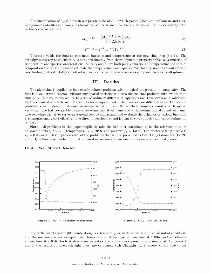
Figure 1. H2 � Air Mueller Mechanism.
Time (s)
Tem
per
atu
re
CH
4
0 5E-06 1E-05 1.5E-052400
2500
2600
2700
2800
2900
3000
3100
3200
-0.01
0
0.01
0.02
0.03
0.04
0.05
0.06
0.07
Figure 2. CH4 � Air GRI-Mech.
The well-stirred reactor (0D combustion) is a temporally accurate solution to a set of initial conditionsand the mixture reaches an equilibrium temperature. A hydrogen-air mixture at 1500K and a methane-air mixture at 2500K, both at stoichoimetric ratios and atmospheric pressure, are simulated. In �gures 1and 2, the results obtained (straight lines) are compared with Chemkin (dots) where we are able to get
4 of 12
American Institute of Aeronautics and Astronautics
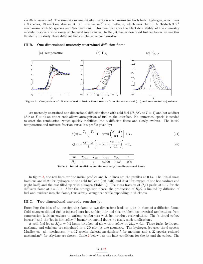
excellent agreement. The simulations use detailed reaction mechanisms for both fuels: hydrogen, which usesa 9 species, 19 reaction Mueller et. al. mechanism10 and methane, which uses the full GRI-Mech 3.011
mechanism with 53 species and 325 reactions. This demonstrates the black-box ability of the chemistrymodule to solve a wide range of chemical mechanisms. In the jet ames described further below we use this exibility to study three di�erent fuels in the same con�guration.
III.B. One-dimensional unsteady unstrained di�usion ame
(a) Temperature
x
(b) YO2
x
(c) YH2O
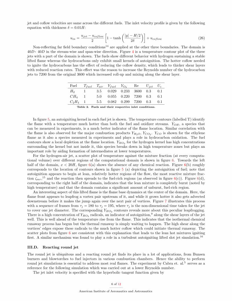
xFigure 3. Comparison of 1D unstrained di�usion ame results from the structured ( ) and unstructed ({) solvers.
An unsteady unstrained one-dimensional di�usion ame with cold fuel (H2=N2 at T = 1) and hot oxidizer(Air at T = 4) on either ends allows autoignition of fuel at the interface. No ‘numerical spark’ is neededto start the combustion, which quickly stabilizes into a di�usion ame and slowly evolves. The initialtemperature and mixture fraction curve is a pro�le given by:
T (x) =Tf � To
2
�1� tanh
�x� 20:1
��+ To (24)
�(x) =�f � �o
2
�1� tanh
�x� 20:1
��+ �o (25)
Fuel Tfuel Tair Yfuel YO2 ReH2 1 4 0.029 0.233 1000
Table 1. Initial conditions for the unsteady one-dimensional ame.
In �gure 3, the red lines are the initial pro�les and blue lines are the pro�les at 0:1s. The initial massfractions are 0:029 for hydrogen on the cold fuel end (left half) and 0:233 for oxygen of the hot oxidizer end(right half) and the rest �lled up with nitrogen (Table 1). The mass fraction of H2O peaks at 0:12 for thedi�usion ame at t = 0:1s. After the autoignition phase, the production of H2O is limited by di�usion offuel and oxidizer into the ame, thus slowly losing heat while expanding in thickness.
III.C. Two-dimensional unsteady reacting jet
Extending the idea of an autoigniting ame to two dimensions leads to a jet in place of a di�usion ame.Cold nitrogen diluted fuel is injected into hot ambient air and this problem has practical applications fromcompression ignition engines to various combustors with hot product recirculation. The ‘vitiated co owburner’5 and the ‘jet in hot co ow’6 burner are model ames to study such applications.
A cold fuel jet at Mjet = 0:3 issues into heated air with a co ow at Mco = 0:1. Three fuels: hydrogen,methane, and ethylene are simulated in a 2D slot-jet like geometry. The hydrogen jet uses the 9 speciesMueller et. al. mechanism,10 a 17-species skeletal mechanism12 for methane and a 22-species reducedmechanism13 for ethylene are chosen. Table 2 below lists the inlet conditions for the jet and the co ow. The
5 of 12
American Institute of Aeronautics and Astronautics
jet and co ow velocities are same across the di�erent fuels. The inlet velocity pro�le is given by the followingequation with thickness � = 0:01H:
uin =ujet � ucoflow
2
�1� tanh
�jyj �H=2
2�
��+ ucoflow (26)
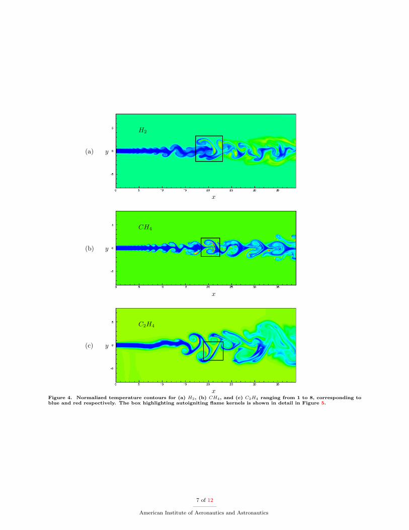
Non-re ecting far �eld boundary conditions14 are applied at the other three boundaries. The domain is40D� 40D in the stream-wise and span-wise direction. Figure 4 is a temperature contour plot of the threejets with a part of the domain is shown. The fuels show di�erent behavior with hydrogen sustaining a stablelifted ame whereas the hydrocarbons only exhibit small kernels of autoignition. The hotter co ow neededto ignite the hydrocarbons has the e�ect of reducing the co ow density, which leads to thicker shear layerswith reduced reaction rates. This e�ect was the reason to increase the Reynolds number of the hydrocarbonjets to 7200 from the original 3600 which increased roll-up and mixing along the shear layer.
Fuel Tfuel Tair Yfuel YO2 Re Ujet Uc
H2 1 3.5 0.029 0.233 3600 0.3 0.1CH4 1 5.0 0.055 0.220 7200 0.3 0.1C2H4 1 5.5 0.082 0.299 7200 0.3 0.1
Table 2. Fuels and their respective inlet conditions.
In �gure 5, an autoigniting kernel in each fuel jet is shown. The temperature contours (labelled T) identifythe ame with a temperature much hotter than both the fuel and oxidizer streams. YOH , a species thatcan be measured in experiments, is a much better indicator of the ame location. Similar correlation withthe ame is also observed for the major combustion products YH2O, YCO2 . YCO is shown for the ethylene ame as it also a species measured in experiments and plays a role in hydrocarbon oxidation. The fuelcontours show a local depletion at the ame location. YHO2 for the hydrogen kernel has high concentrationssurrounding the kernel but not inside it, this species breaks down in high temperature zones but plays animportant role by aiding formation of intermediates at lower temperatures.
For the hydrogen-air jet, a scatter plot of temperature against the mixture fraction (at every computa-tional volume) over di�erent regions of the computational domain is shown in �gure 6. Towards the lefthalf of the domain, x < 20H, �gure 6(a) shows the absence of any chemical reaction. Figure 6(b) roughlycorresponds to the location of contours shown in �gure 5 (a) depicting the autoignition of fuel; note thatautoignition appears to begin at lean, relatively hotter regions of the ow, the most reactive mixture frac-tion �mr,15 and the reaction then spreads to the fuel-rich regions (as observed in �gure 6(c)). Figure 6(d),corresponding to the right half of the domain, indicates that the lean mixture is completely burnt (noted byhigh temperature) and that the domain contains a signi�cant amount of unburnt, fuel-rich region.
An interesting aspect of this lifted ame is the ame base dynamics at the center of the domain. Here, the ame front appears to leapfrog a vortex pair upstream of it, and while it grows hotter it also gets advecteddownstream before it makes the jump again over the next pair of vortices. Figure 7 illustrates this processwith a sequence of frames from �j = 180 to �j = 195, where �j is the non-dimensional time taken for the jetto cover one jet diameter. The corresponding YHO2 contours reveals more about this peculiar leapfrogging.There is a high concentration of YHO2 radicals, an indicator of autoignition,9 along the shear layers of the jetwell. This is well ahead of the temperature rise from the ame. This indicates that the isothermal chemicalrunaway process has begun but the thermal runaway is simply waiting to happen. The high shear along thevortices’ edges expose these radicals to the much hotter co ow which could initiate thermal runaway. Thescatter plots from �gure 6 are consistent with this explanation that leads to the lean hot mixtures igniting�rst. A similar mechanism was found to play a role in a turbulent autoigniting lifted slot jet simulation.16
III.D. Reacting round jet
The round jet is ubiquitous and a reacting round jet �nds its place in a lot of applications, from Bunsenburners and blowtorches to fuel injectors in various combustion chambers. Hence the ability to performround jet simulations is essential to address most real ames. The experiment by Cabra et. al.5 serves as areference for the following simulation which was carried out at a lower Reynolds number.
The jet inlet velocity is speci�ed with the hyperbolic tangent function given by
6 of 12
American Institute of Aeronautics and Astronautics
(a)
H2
y
x
(b)
CH4
y
x
(c)
C2H4
y
xFigure 4. Normalized temperature contours for (a) H2, (b) CH4, and (c) C2H4 ranging from 1 to 8, corresponding toblue and red respectively. The box highlighting autoigniting ame kernels is shown in detail in Figure 5.
7 of 12
American Institute of Aeronautics and Astronautics

(a)
T YOH YH2 YH2O YHO2
(b)
T YOH YCH4 YCO2 YH2O
(c)
T YOH YC2H4 YCO2 YCO
Figure 5. Autoigniting ame kernels for (a) H2, (b) CH4, and (c) C2H4.
(a) x = [0; 20] (b) x = [20; 22:5]
(c) x = [22:5; 25] (d) x = [25; 40]
Figure 6. Scatter plot of temperature against mixture fraction at various intervals of x (in units of jet width H). Theautoignition of H2 at lean conditions is evident in (b) and (d) indicates that the lean mixtures have completely burnt,while there is still unburnt rich fuel indicated by the thick line at the bottom right corner.
8 of 12
American Institute of Aeronautics and Astronautics

.
�j = 180
�j = 183
�j = 186
�j = 189
�j = 192
�j = 195
(a) (b)Figure 7. Temporal evolution of (a) temperature and (b) YHO2 at the base of the lifted H2 � Air ame from �j = 180to �j = 195.
9 of 12
American Institute of Aeronautics and Astronautics

uin =ujet � ucoflow
2
�1� tanh
�r �D=2
2�
��+ ucoflow (27)
For this calculation, � = 0:01D. The Reynolds number of the jet is Rejet = 7200 and the domainsize is 40D� 40D� 40D. Non-re ecting boundary conditions14 are applied at the side and exit boundaries.Turbulent uctuations (in the form of homogeneous isotropic turbulence) are not added to the inlet, as iscommonly done in DNS studies of turbulent autoigniting ames.16 Improved transport properties are takeninto account with viscosity modi�ed by temperature, modelled with a power law, �=�� = (T=T�)0:67, and thedi�erent species are allowed to have di�erent Schmidt numbers.17 The e�ect of Lewis numbers on hydrogen ames is important and can a�ect autoignition times and intensities.3,18 This simulation took a total of 0:3million cpu-hours and was run on 1024 cpu-cores for 12:5 days for 1 ow-through time of the domain.
At these conditions, a laminar ame close to the inlet is observed. Figures 8(a) and 8(b) show the contoursof temperature and YOH which are correlated with a lifted ame height of x = 4D. YHO2 in 8(c) howeveris leading the ame by almost one jet diameter, again indicating an autoignition based ame stabilization.Figure 9 illustrates an instantaneous cutaway of isosurfaces and we can see the substantial buildup of YHO2
radicals followed by the temperature increase.A plausible reason for this ame remaining laminar in spite of the high Reynolds number can be down to
the high viscosity of the hot co ow. The e�ect of hydrogen’s low Lewis number also leads to faster ignition3
and further increases the temperature and hence viscosity downstream of the ame. This e�ect is also clearin �gure 8(d) where the mixture fraction shows increased di�usion downstream of the ame anchor location.
(a)
x
y
(b)
x
y
(c)
x
y
(d)
x
y
Figure 8. Contour plots of (a) Temperature, (b) YOH , (c) YHO2 , and (d) Mixture fraction � for the round jet.
*
Flow
Figure 9. Flame cutaway superposing the two sets of isosurfaces, the bluish-gray isosurfaces of YHO2 positioned belowthe orange temperature isosurfaces indicate that the ame is stabilized by autoignition.
10 of 12
American Institute of Aeronautics and Astronautics
IV. Summary and future work
Ongoing work on the development of an algorithm to solve turbulent reacting ows is presented. Thesemi-implicit source term discretization molli�es the sti�ness associated with the chemical source termswhile simultaneously allowing explicit methods for advection and di�usion. This segregated formulationallows us to independently modify the compressible Navier-Stokes, species and chemical source term partsof the complete solver. Colocated variable storage allows this algorithm to be extended to structured andunstructured formulations seamlessly. The chemical mechanism module allows us to simulate multiple fuelseasily and the simulations in this paper demonstrate this capability.
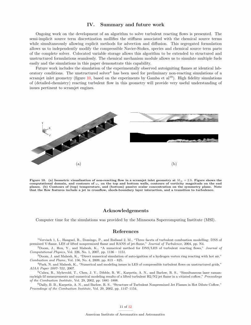
Future work includes the simulation of the experimentally observed autoigniting ames at identical lab-oratory conditions. The unstructured solver4 has been used for preliminary non-reacting simulations of ascramjet inlet geometry (�gure 10, based on the experiments by Gamba et al19). High �delity simulationsof (detailed-chemistry) reacting turbulent ow in this geometry will provide very useful understanding ofissues pertinent to scramjet engines.
(a) (b)
Figure 10. (a) Isometric visualization of non-reacting ow in a scramjet inlet geometry at M1 = 2:9. Figure shows thecomputational domain, and contours of !z on the top and bottom walls, contours of vorticity magnitude on the endplanes. (b) Contours of (top) temperature, and (bottom) passive scalar concentration on the symmetry plane. Notethat the ow features include a jet in cross ow, shock-boundary layer interaction, and a transition to turbulence.
Acknowledgements
Computer time for the simulations was provided by the Minnesota Supercomputing Institute (MSI).
References
1Vervisch 1, L., Hauguel, R., Domingo, P., and Rullaud 2, M., \Three facets of turbulent combustion modelling: DNS ofpremixed V- ame, LES of lifted nonpremixed ame and RANS of jet- ame," Journal of Turbulence, 2004, pp. N4.
2Doom, J., Hou, Y., and Mahesh, K., \A numerical method for DNS/LES of turbulent reacting ows," Journal ofComputational Physics, Vol. 226, No. 1, 2007, pp. 1136 { 1151.
3Doom, J. and Mahesh, K., \Direct numerical simulation of auto-ignition of a hydrogen vortex ring reacting with hot air,"Combustion and Flame, Vol. 156, No. 4, 2009, pp. 813 { 825.
4Park, N. and Mahesh, K., \Numerical and modeling issues in LES of compressible turbulent ows on unstructured grids,"AIAA Paper 2007{722 , 2007.
5Cabra, R., Myhrvold, T., Chen, J. Y., Dibble, R. W., Karpetis, A. N., and Barlow, R. S., \Simultaneous laser raman-rayleigh-lif measurements and numerical modeling results of a lifted turbulent H2/N2 jet ame in a vitiated co ow," Proceedingsof the Combustion Institute, Vol. 29, 2002, pp. 1881{1888.
6Dally, B. B., Karpetis, A. N., and Barlow, R. S., \Structure of Turbulent Nonpremixed Jet Flames in Hot Dilute Co ow,"Proceedings of the Combustion Institute, Vol. 29, 2002, pp. 1147{1154.
11 of 12
American Institute of Aeronautics and Astronautics
7Mastorakos, E., Markides, C., and Wright, Y. M., \Hydrogen autoignition in a turbulent duct ow: Experiments andModelling," Conference on Modelling Fluid Flow , 2003.
8Oldenhof, E., Tummers, M., van Veen, E., and Roekaerts, D., \Ignition kernel formation and lift-o� behaviour of jet-in-hot-co ow ames," Combustion and Flame, Vol. 157, No. 6, 2010, pp. 1167 { 1178.
9Mastorakos, E., \Ignition of turbulent non-premixed ames," Progress in Energy and Combustion Science, Vol. 35, No. 1,2009, pp. 57 { 97.
10Mueller, M. A., Kim, T., Yetter, R. A., and Dryer, F. L., \Flow Reactor Studies and Kinetic Modeling of the H2/O2Reaction," International Journal of Chemical Kinetics, Vol. 31, 1999, pp. 113{125.
11Smith, G. P., Golden, D. M., Frenklach, M., Moriarty, N. W., Eiteneer, B., Goldenberg, M., Bowman, C. T., Hanson,R. K., Song, S., Gardiner, W. C., Jr., V. V. L., and Qin, Z., http://www.me.berkeley.edu/gri mech/ .
12Sankaran, R., Hawkes, E., Chen, J., Lu, T., and Law, C., \Structure of a spatially developing turbulent lean methane airBunsen ame," Proceedings of the Combustion Institute, 2007, pp. 1291{1298.
13Wang, H., Personal communication, 2012.14Poinsot, T. J. and Lele, S. K., \Boundary conditions for direct simulations of compressible viscous ows," Journal of
Computational Physics, Vol. 101, 1992, pp. 104{129.15Mastorakos, E., Baritaud, T., and Poinsot, T., \Numerical simulations of autoignition in turbulent mixing ows," Com-
bustion and Flame, Vol. 109, No. 12, 1997, pp. 198 { 223.16Yoo, C. S., Sankaran, R., and Chen, J. H., \Three-dimensional direct numerical simulation of a turbulent lifted hydrogen
jet ame in heated co ow: ame stabilization and structure," Journal of Fluid Mechanics, Vol. 640, 2009, pp. 453{481.17Hawkes, E. R. and Chen, J. H., \Direct numerical simulation of hydrogen-enriched lean premixed methane-air ames,"
Combustion and Flame, Vol. 138, 2004, pp. 242{258.18Doom, J. and Mahesh, K., \DNS of auto-ignition in turbulent di�usion H2/air ames," 2009.19Gamba, M., Miller, V. A., Mungal, G., and Hanson, R. K., \Ignition and Flame Structure in a Compact Inlet/Scramjet
Combustor Model," AIAA Paper 2011{2366 , 2011.
12 of 12
American Institute of Aeronautics and Astronautics