a p r cents 1 9 3 the copy - americanradiohistory.com · a p r cents 1 9 3 the copy vacuum tub...
TRANSCRIPT

-
A p r cents1 9 3 the copy
Vacuum Tub PrecisionOscillators Oscillator
KGFW G"A Bea
TheIonosp
9!TRS - - The
Radio Social
hip, Air,roadcast
A MONTHLY JOURNAL DEVOTED TO TM?. COMMERCIAL RADIO & ALLIED FIELD
EVERY RADIO MAN WANTS BOOKS
Wynapes ofRADIO
dr
PRINCIPLES OF RADIOBy KEITH HENNEY
(2nd Edition) Published in 1934.For the Experimenter, Technician, Ser-
viceman, or Amateur. This well knownauthor, editor, and technician, contributesa fine work that will help the radio manin many a problem. Written in simple andeasily understood language. Among othersubjects television, and facsimile trans-mission are described. Calculation of se-lectivity, impedance and parallel circuits,voltmeter method of measuring resonance,audio amplifier design, bridge neutralizingsystems, measuring coil resistance, antennacapacity, inductance, wavelengths, ultra highfrequency amplifiers, Class B. amplification,Class C. radio frequency amplifiers all clear-ly described.491 pages, PA X 774 $3.50
PRINCIPLES OF RADIO COMMUNICATION
By JOHN H. MORECROFTProf. of Electrical Engineering, Columbia University
(3rd Edition) Published in 1933
Fundamental Ideas and Laws; Resistance-Inductance-Capa-city-Shielding-Laws of oscillating circuits; Spark Telegraphy;Vacuum Tubes and Their Applications; Continuous NVave Tele-graphy; Antennas and Radiation; Amplifiers; all thoroughlytreated in this wonderful book of 1084 pages, size 6 X 9 inches.A right up to the minute book by an author who needs no in-troduction to radio men $7.50
THESE ARE BOOKS YOU NEEDRadio Traffic Manual and Operating Regulations.
by Duncan & Drew (1929) $2.00How to Pass U. S. Gov't Radio License Examinations,
by Duncan & Drew (2nd edition, 1932) 2.00Principles of Radio Communication, by J. H. More -
croft (3rd edition, 1933) 7.50Elements of Radio Communication, by J. H.
Morecroft 3.00The Radio Manual, by George E. Sterling (2nd edition
1933) 6.00Radio Telegraphy and Telephony, by Duncan & Drew
(2nd edition, 1931) 7.50Radio Frequency Electrical Measurements, by Hugh
A. Brown 4.00Perpetual Trouble Shooters Manual No. 1, by John
F. Rider 7.50Perpetual Trouble Shooters Manual No. 2. by John
F. Rider 6.50Perpetual Trouble Shooters Manual No. 3, by John
F. Rider 7.50Perpetual Trouble Shooters Manual No. 4. by John
F. Rider 7.50
We will get any book published or any group of books and ship underone cover, if possible, within 24 hours after receipt of your order.Give complete title and author's name, and if possible publisher. Writeyour name and address clearly, or print it to make no doubt.
Electron Tubes and Their Ap-plication, by John H. More -croft (1933) 458 Pages $4.50
Theory of Thermionic Tubes,by Prof. E. Leon Chaffe, 652Pages, 357 illustrations $6.00
Radio Engineering, by Freder-ick E. 'Ferman, 750 pages, 418illustrations $5.00
High Frequency Measure-ments, by August A. Hund
$5.00
Televison-lts NI ethods andUses. by Edgar Felix $2.50
Radio Construction and Re-pairing, by James Moyer andJohn F. Wostrill (4th Edition)
$2.50
Radio Engineering Handbook,by Keith Hennev (583 pages)
x 7 in. $5.00
RADIO OPERATINGQUESTIONS AND
ANSWERSNilson & Hornung
By Arthur R. Nihon, Lieuten-ant ( Technicist) (Communica-tions) U. S. N. R. (Retired), andJ. L. Hornung, Radio Ins. ructorNew York University. 5th edition388 pages, 5%x8, 96 illustrations
$2.50
This book gives over 600 questionsand answers covering all radio op-erator license examinations. Ques-tions are typical of those used onexaminations; answers are fulland well illustrated. This editionhas been enlarged to include infor-mation on broadcasting, marine,aeronautical, police and amateur ra-dio operating and contains manynew questions and answers on newtransmitters, new radio laws andlicense regulations, etc.
Send Check or Money Order Only. Do Not Send Cash
BOOK DEPARTMENT, CQ Magazine Co.7 West 44th Street NEW YORK, N. Y.

PUBLICATION OFFICENEW YORK
7 West 44th StreetPhone: VAnderbilt 3-8091
VOLUME IV NO. r,
JAMES J. DELANEY,Editor
L. D. McGEADY,Business Manager-----Associate Editors:
BALTIMORE, MD.Wm. D. Kelly, WFBR
BOSTON, MASS.Harry R. Chetham
Somerville, Mass., Police RadioCROWN POINT, IND.
Fred F. HallST. LOUIS. MO.
C. H. Stoup. WIL
WHILE Congress is wrestling withmighty problems it seems premature
to think that a new member will he addedto the President's official family in theform of a Communications Commissioner.
True, the seven men acting as TheCommunications Commission, divided inthree divisions, the Broadcast Division,the Telegraph Division, and the Tele-phone Division, have their hands full.
Perhaps as some suggest local officeshandling all district matters; only refer-ring to Washington headquarters forgeneral opinions, would simplify the task.Perhaps, this would also eliminate thenecessity for the large commercial firm -maintaining their Capitol contact offices.It would also eliminate the necessity ofthe smaller ones having to trip to Wash-ington to get satisfactory hearings.
A great emergency would of course im-mediately solidify under one control thisimportant communications problem, andit is not likely that the control would remain divided by seven.
But, the immediate future does not in-dicate any particular demand or necessityfor a Commissioner of Communications.This is particularly true when viewedfrom the fact that the present Communi-cations Commission is doing their jobvery nicely.
(FORMERLY "C -Q")The Only Mago:iiie in America Devoted Entirely to the Commercial Radio Man
Contents for April, 1935
Page
Positive grid oscillator, range 500 to 550 megacycles - Front Cover
Vacuum Tubes as High Frequency Oscillators
By M. J. Kelly and A. L. Samuel 5
New Survey Shows 21,455,799 U. S. Radios 7
Song of The Spark SetBy Herman Swerdloff 7
Shipping Items of Interest - 7
How KGFW Got "A Beat"By Roy H. McConnell - 8
The IonosphereBy W. M. Goodall
Line Equalization
- 9
By Robert C. Moody - - - - 10
"In Baltimore"By Wm. D. Kelly - - 10
Forced Air RecommendedBy S. S. Davis - 10
Applications for New Broadcasting Stations - - 11
Station KROW - - - 11
News from Radio Manufacturers - - - - - 12
'I'RS-The Radio Social - - - - 13
An Adjustable Oscillator of High PrecisionBy L. Armitage - - -
Columbia Goes Into Service
\ ssignments
New Apparatus
14
16
16
22
Published Monthly by CQ Magazine Company, 7 West 44th Street, New York.N. Y., Phone VAnderbilt 3-8091. Yearly subscription rate $2.00 in U. S. and Canada;2240 foreign. Make all checks, drafts and money orders: payable to the Company.Single Copies, 20 cents. Tcxt and illustrations of this Magazine are copyrighted, andmust not be reproduced without permission.
Page Three

Rider's Manual Volume VIS READY!
JUST AN IDEAof how extensively Volume V coversthe field. This is a partial list ofthe manufacturers in Volume V.
Quantity of Quantity ofName Models Name Models
NEVER before in the history of Radio has such a stupendous com-pilation of technical servicing material been collected between
two covers. Expense was not spared to make Rider's Volume V all -embracing in its scope. Sets are explained even more lucidly thanthose of yesteryear, for complications galore are incorporated in 1935receivers. Seeing is believing-prove to yourself that Rider's Vol-ume V is without doubt the servicing sensation of the year-betterthan an other manual-the absolute peer!
Acratest 9 Hudson Ross 5Air King 5 Insulin 6 Rider's Volume V hasAlliedAnsley
215
InternationalKingston
1910 More schematics . . . more chassis layouts . . .
Atwater -Kent 36 Lafayette 26 more I -F. peaks . . . more alignment data . . . more trimmerAudiola 11 Lang 5 locations . . . more circuit descriptions . . . more socket layoutsAutocrat 6 Larkin 3 . . . more parts lists . . . assembly wiring diagrams . . . more13alkeitBelmont
716
LewolMission -Bell
56 and better everything than any other manual!
Bosch 19 Montgomery -Ward 13Colonial 16 Noblitt-Sparks 11Crosley 25 Philco 19Detrola 7 Pilot 10Dewald 24 Radolek 13 946 Models 1200 PagesEchophone 6 RCA -Victor 63Edison -Bell 7 R. K. Labe 4Elec. Spec. Export 5 Sears Roebuck 56 112 ManufacturersEmerson 13 Sentinel 26Empire 8 Sparton 16Erla 12 Stewart -Warner 38Fairbanks -Morse 22 Supreme Inst. 9Federated Tatro 5 Volume I . . . 1000 pages . $7.50 Volume IV . 1040 pages . $7.50Purchaser 27 Webster 8 Volume II . . 800 pages . $6.50 Volume V . 1200 pages . $7.50Ford Motor 4 T. C. A. 12 Volume III . 1070 pages . $7.50 Servicing Superheterodynes . $1Fordeon 7 Wells Gardner 12General Electric 40 Westinghouse 11Gilfillan 13 Weston Inst. 20Grunow 19 Wilcox Gay 13Halson 6 Wurlitzer 8 Sold with a Money -back GuaranteeHorn 5 Zenith 21
JOHN F. RIDER, Publisher 1440 BROADWAY
NEW YORK, N. Y.
Page Four

`Vacuum Tubes as High -Frequency Os-cillators*By M. J. KELLY and A. L. SAMUEL
Vacuum tubes as oscillators and amplifiers at frequencies greater than100 megacycles (3 m.) are considered in this paper. The type of construc-tion used in a large number of different tubes, and the characteristics of thetubes, are presented. Circuits for operating the tubes also are presented.Circuits for operating the tubes also are considered and the theory of oper-ation and the factors limiting ultra -high frequencies are discussed. Principalattention is given to the tubes as oscillators, with brief consideration of theproblem of amplification.
THE three types of oscillation genera-tors1. which at present are the most
efficient in the range from 100 inegacy-
so
70
60
n 50
40
4.
30
20
10
010 20 30 40 50 60 70 80 90
FREQUENCY IN MEGACYCLES PER SECOND
with substantially undiminished efficiencyand output. In this range the fre-quency at which a tube is to be employed
100
80
70
60
z
50cc
z40
w
305
20
10
0110
Fig. 1-Power output and anode efficiency as a function of frequencyfor a standard tril'ide. These carves are typical of all tubes au they ap-
proach their upper limiting frequency
des to 3000 megacycles per second willbe discussed in the following survey.These are: the negative grid tube whichat lower frequencies is the conventionalregenerative oscillator, the positive gridor Barkhausen oscillator, and the "mag-netron" oscillator. The amplification prob-lem will be briefly discussed. Becauseof the present unsettled state of the the-ory, only the most elementary and gen-erally accepted part will be included.Much theoretical and experimental workremains to be done before knowledge ofthe mechanism of oscillation and amplifi-cation in this frequency range will besatisfactory. As is often the case, theempirical knowledge of some of thesemechanisms has outdistanced the theor-etical interpretation.
The Negative Grid OscillatorThe conventional thermionic vacuum
triode, whether it be a large water cooledpower tube or a small receiving tube, maybe used as a generator of oscillations va-rying in frequency from a few cyclesper second to some 20 or 30 megacycles
*Presented at Winter Convention A. I.E. E., January 22-25, 1935. Reproducedby courtesy of The Bell System Techni-cal Journal, January, 1935.
CI
co
L0
I 11 I
is a factor of almost negligible import-ance in the determination of its charac-teristics and its form. Beyond this range,however, frequency plays an increasinglyimportant part, and as one approaches300 megacycles, it becomes the most im-portant factor in the determination oftube design.
When an attempt is made to operate astandard triode at increasingly high fre-quencies it is found that the output andefficiency begin to decrease. The frequen-cy at which this is first observed will de-pend upon the design of the tube but itwill usually be in the 10- to 60 -megacyclerange. By successive modification of thecircuit arrangement and size this de-crease in power output and efficiency canhe minimized. With optimum circuit ar-rangements, however, this decrease con-tinues until finally a frequency is reachedbeyond which oscillations can no longerbe produced.
In Pig. 1 are shown typical data for astandard 75 -watt tube, the Western Elec-tric type 242A, operated with reducedpotentials over the frequency range fromthe point where oscillation frequency no-ticeably affects performance to the pointwhere oscillations can no longer be pro-duced. The plate potential was held con-stant at 750 volts throughout the entirefrequency range. The oscillation circuitwas modified at each point in order toobtain. maximum output and efficiency,keeping the anode dissipation within themaximum rating of 100 watts and theanode circuit within the maximumrating of 0.150 amp. It can be seen fromthe curves that the output and efficiencyare independent of the frequency untilabout 20 megacycles is reached, whenthey begin to decrease. At 100 megacy-cles tie output power is only 2.5 wattsand the efficiency only 2 per cent. Thetube will not oscillate at 105 megacycles.
LGCG
Lp
CFpXCFGCt = CGP CFP CFG
Lt = LG +Lp
Fig. 2 (lef 1)-A standard Colpitts oscillator circuit. The heavy linesindicate the main oscillating circuit. The dotted portions represent the in-ter -electrode capacitances and lead inductances which play a minor role at
low frequencies
Fig. 3 (right)-The limiting circuit with the external tuning capaci-tance eliminated and the external inductance reduced to a short circuitingbar between the grid and plate leads. The main oscillating circuit, Indi-cated by the heavy lines, is seen. to include the inter -electrode capacitances
and lead inductances
Page Five
(A) (B)
+100
Fig. 4-Illustrating the mechanism which enables electrons to take energyfrom the oscillating circuit.
Effect of Energy Losses on PerformanceA tube operating in the range where
frequency affects performance must with-stand energy losses, and the resultingheating within its structure, which occurto only a negligible degree at the lowerfrequencies. Some of these losses are dueto dielectric hysteresis in the insulatingmaterials of the tube, particularly in theportions of the glass supporting stem orbulb which lies between the tube leads.The glass is sometimes so softened bythe heat thus developed that it is punc-tured by the outside air pressure. Lossesalso occur in the auxiliary metallic partsof the tube structure due to the increasededdy currents that occur at high fre-quencies. Losses in the tube electrodesand their lead-in wires are also greatlyincreased due to skin effect which in-creases their resistance, and due to theincreased charging current required bythe inter -electrode capacitances. The in-creased lead temperature, depending up-on its amount, will cause a more or lessrapid deterioration of the lead -to -glassseals which may ultimately destroy thevacuum. In order to protect the tubefrom damage because of these new typesof energy dissipation, the operating po-tentials and currents must be reduced tovalues less than those established for low -frequency operation. Some manufacturersare now giving special ratings on suchof their standard tubes as may be usedat ultra -high frequencies. These ratingsshould be adhered to when operating inthis range.
Effect of Circuit on PerformanceThe decrease in output power and plate
efficiency which sets in with the increasein frequenc7, while due in part to thelosses described above, and to the rapidincrease in radiation losses, is also dueto two additional effects of fundamentalimportance. The first to become evident,with increasing frequencies, is circuitalin nature. This can be explained by ref-erence to the conventional oscillatorshown in Fig. 2. The frequency of suchan oscillator is given by
1
f =2:EN/LC
where L and C are the effective induc-tance and capacitance of the oscillat-ing circuit. In the lower frequencyrange the LC product which determinesthe frequency is substantially equal toLA, that is, to the product of the induc-tance and capacitance of the externalcircuit. The inductance of the tube leads
Page Six
and the capacitance between its elec-trodes (indicated by the dotted lines inthe figure) play a negligible role. Inorder to tune the circuit to higher andhigher frequencies, the capacitance Cois first reduced and finally eliminated,leaving the inter -electrode capacitanceas the only capacitance in the oscillat-ing circuit. The tube leads then form apart of the main oscillating circuit, inwhich large circulating currents must ex-
ist for stable operation. For a furtherincrease in frequency the external induc-tance Lo must be reduced and, in thelimit, it becomes the shortest possibleconnection between the grid and plateterminals. The oscillating frequencyfor this limiting circuit, shown in Fig. 3,is determined by the product of the leadinductance Lt and the inter electrode ca-pacitance Ct that is,
1
2m./Lteiwhere Lt is the sum of the grid andplate lead inductance and C, is the totalgrid -plate capacitance. Even before thisfrequency limit is reached the outputpower and plate efficiency are seriouslyreduced by the lack of full control overthe relative amplitude and phase of thealternating grid and plate potentials.Whereas the ratio of these amplitudes iscontrolled in the circuit shown in Fig. 2by the condensers C, and C,, it is deter-mined in the limiting case primarily bythe fixed ratio of the grid -filament toplate -filament inter -electrode capacitance.Most tubes made especially for ultra-high frequency use are constructed so asto minimize these circuit limitations bya reduction in the inter -electrode capac-itance and lead inductance and by ad-justing the capacitance ratio.Effect of Transit Time on Performance
The second fundamental has to do withthe time required for the electrons to
(Continued on Page 17)
Fig. 5-A radiation cooled tube for use in the frequency'range from 60 to 180 megacycles per second. Note the large ratioof the plate diameter to plate length and the special arrangement
of the leads

New Survey Shows 21,455,799 U. S. RadiosThere are 25,551,569 radio receiving
sets in 21,455,799 homes in the UnitedStates -more than twice the number ofresidence telephones -and the total num-ber of radio listeners over 10 years ofage is placed at 70,804,137. These newfigures are contained in what is believedto be the most comprehensive radio sur-vey ever undertaken and just released bythe Columbia Broadcasting System incooperation with the statistical staffs ofDr. Daniel Starch, noted research expert,and of the McGraw-Hill Publishing Co.
The survey required a year of investi-gation by a nationwide field staff whichmade 125,000 house -to -house interviewsIn 321 communities, covering cities, smalltowns and farms in every state and stud-ying every type of family in the variousincome brackets.
A breakdown by states of the numberand percentage of radio -equipped homesin each, as given in the survey, follows:
No. of Radio Owner -State Families Homes ship
Alabama 602;200 216,979 36.0Arizona 111,500 53,518 48.0Arkansas 446,700 122,989 27.5California 1,759,400 1,369,365 77.8Colorado 270,800 186,598 68.9Conn. 403,700 339,845 84.2Delaware 60,500 45,898 75.9Dist. of, Col. 127,400 121,787 95.6Florida 403,800 200,674 49.7Georgia 661,600 260,011 39.3Idaho 109,300 74,284 68.0Illinois 2,019,500 1,647,283 81.6Indiana 869,500 597,696 68.7
SONG OF THE SPARK SET
By HERMAN SWERDLOFF
I am just a bit of copper and black pan-el,
I'm beloved by the Komrades of theKey,
You've heard me call out in the EnglishChannel,
My mellow voice was calling POZ.My brass is always shining very bright-
ly,My gaps are ozone -filled and sparking
right,My motor smoothly runs like the whirl-
ing Cosmic Suns,And my Leydon jars discharge their
purple light.
They read the bold defiance in yoursending
As I hurled your SOS across the sea,And tho my dying note was rather feeble
They caught your message on the "Ka-tydee";
For sixty-seven hours we were drifting,Our decks were battered by that hell-
ish sea,And that lion roaring wind left our rig-
ging far behind,While the whiplashed ratline shrieked
their melody.
You pounded out: "There's water in thebilges,
The starb'd side is listing very fast."With your fist upon the key you pound-
ed CQD,And I stuck with you, Shipmate, to
the last;
No. of Radio Owner -State Families Homes ship
Iowa 637,200 459,988 72.2Kansas 488,500 319,714 65.4Kentucky 617,900 300,877 48.7Louisiana 503,700 258,420 51.3Maine 201,000 136,840 68.1Maryland 397,900 318,877 80.1Mass. 1,057,300 903,467 85.5Michigan 1,242,200 919.946 74.1Minnesota 619,500 441,164 71.2Mississippi 478,400 113,989 23.8Missouri 943,300 649,040 68.8Montana 137,900 86,011 62.4Nebraska 348,700 244,503 70.1Nevada 26,900 16,370 60.9New Hamp. 120,500 94,186 78.2New Jersey 1,032,000 895,884 86.8New Mexico 101,600 43,394 42.7New York 3,264,700 2,928,870 89.7No. Carolina 673,700 266,924 39.6No. Dakota 146,400 84,138 57.5Ohio 1,752,800 1,336,547 76.3Oklahoma 589,300 291,595 49.5Oregon 275,000 211,103 76.8Penn. 2,285,100 1,913,349 83.7Rhode Is. 171,900 148,961 86.7So. Carolina 372,300 142,706 38.3So. Dakota 164,000 103,342 63.0Tennessee 622,300 312,491 50.2Texas 1,445,900 733,128 50.7Utah 118,200 84,293 71.3Vermont 90,300 61,274 67.9Virginia 531,700 301,894 56.8Washington 434,600 333,236 76.7West Va. 388,300 239,227 61.6Wisconsin 732,900 489,602 66.8Wyoming 59,500 33,522 56.3
U. S. Total 30,919,300 21,455,799 69.4
And yet you thot that this would be yourfinish,
That your love at home would neversee your bones,
But the gallant "Katydee" hove to inangry sea,
And snatched another prize from Da-vy Jones.
Do you recall that rough coast of Alas-ka?
The North winds and the icy roaringsea,
The night all lives were lost on the "So-phia"
You flashed the tragic story with yourkey;
You reckon how I raised that LimeyStation?
You relayed twenty TR's on the air,When the static was so bad that you
swore till you were mad,But the Limey said my spark rolled
in quite fair.
You recollect those wild Straits of Ma-gellan?
The engine crushed the Third Assis-tant's hand,
But I hurled his painful plea across athousand miles of sea,
And the doctor gave advice from Lub-ber's land.
I've saved the sinful souls of shipwreckedsailors
Who prayed and prayed to God with-out avail,
But my kilowatt of spark saved themfrom the hungry snark
AnJ brought them back alive to tellthe tale.
Shipping Items of InterestVessels under construction in U. S.
yards March 1, 1935, were of estimatedgross tons 34,990. The largest of thesewas two 9,000 ton tankers in the NewYork S. B. Co. All the others were under1,000 tons. The total includes barges,tankers, towboats, fishing vessels, tugsand ferry boats.
At Boston a conference on the coordi-nation of distress communications washeld recently in the Commandant's office,Boston Navy Yard. Represented at theconference was Navy, Coast Guard, Light-house Service, Inspector of Steam Ves-sels, representatives of several steamshiplines, as well as the commercial wirelessfirms.
The International Federation of Ra-diotelegraphists recently sent out the fol-lowing notice: To all members of theaffiliated associations. Automatic AlarmDevice. In order to get an opinion of theworking of the above instruments onboard the ships, we would ask you to sup-ply the Federation with information re-garding your experience with this appa-ratus. It is therefore kindly requestedthat you will fill in the form and send itto your national association as soon aspossible. It should be understood that weare only interested in strictly neutral in-formation which can show the actualWorking of the Automatic Alarm Devicein the Safety Service at Sea. Yours faith-fully, International Federation of Radio -
telegraphists.
Commerce Men Have Hard TimeAt the Mount Catherine beacon light
on the Seattle -Spokane airway sectioncommerce department men had to digtunnels in snow to make their inspections.The snow was 24 feet deep, and four feetabove the exhaust pipes from the gaso-line engines in the shed. Heat from theexhaust pipes kept holes open in the snowso that the shed could be found. It tookthe men five hours digging snow to getin to make their inspection. That's workfor radio men.
I've made your lonely cruise a cheerfulpassage.
My waves of sparks have conqueredwaves of sea;
Far I sentinel the air when the shipsare in despair
And my shipmate is the pounder ofthe key.
We've sailed the seven lonely seas to-gether,
We've felt that pride that only sea-men know,
In our conquest of the sea with myspark gaps and your key,
Yet we've danced with death a dozentimes or so.
They say ashore that you have been afailure.
It doesn't matter what you might havebeen,
But where sky and water meet you're the- PRIDE of every fleet,And they hail you as the savior of the
seaOur silent deeds are written on time's
pagesThat the restesa roving sons of men
may see,And with every storm that rages they
will hear in distant agesThe saga of the SPARKS upon the
sea.
Page Seven
How KGFW Got "a Beat"Stratosphere Balloon Descent Was the Opportune Moment With Equipment on Hand
By ROY H. McCONNELL, Chief Eng. KGFWIF some one had told staff members of
radio station KGFW that they wouldbroadcast the descent of the stratosphereballoon when preparations were beingmade for its flight into the high alti-tudes, I am very sure they would havedone some tall laughing.
Yet that is just what happened. How-ever, no one excepting those who live in
out of the gondola. Ile said, "I thoughtmaybe your listeners would like to knowabout the balloon." We thanked him forthe information and relayed it on to ourlisteners.
By this time we were getting numer-ous phone calls from persons askingabout the sphere and also calls bearingnews of its whereabouts. Probably fif-
K
The KGFW Shack. Verle Edminston, Announcer,Operator, Shown
central Nebraska have ever heard aboutit for the press avoided mentioning thefact. Perhaps you have heard that thenewspapers don't care much for radiostations. This would seem to prove theassertion as no mention was made regard-ing the fact that KGFW broadcast thelast two hours of the descent of the strat-osphere balloon, giving data on the descent at frequent intervals.
Our first information regarding theflight of the balloon came from a list-ener who sent us a telegram from Goth-enburg, Neb. He said, "The stratosphereballoon is right over my house, think it isabout two miles up, seems to be in trou-ble, we can see something hanging looseon one side of the bag. It looks to beabout three inches in diameter. Thoughtmaybe you would like to tell your list-eners about it." This we proceeded to doimmediately. About thirty minutes laterwe received a telephone call from a far-mer who said that he lived about tenmiles north of Sumner, Neb., and thatthe balloon was at that moment passingover his house. He thought that it wasabout two miles high and that all wasnot well aboard. With the aid of a smalltelescope he could see that some of therigging was misplaced and he believedthat one of the passengers was partlyPage Eight
and M. E. Thrlen,
teen minutes later we sighted the balloonwest of the station. It was coming out ofa cloud, looked about as large as a com-mon marble and appeared to be White incolor. The stratosphere seemed to remainalmost stationary, as to height, for sev-eral minutes and then started to settle.It was drifting rapidly southeast and be-gan to sink speedily towards the earth.
Perhaps twenty minutes after it beganto settle, the balloon collapsed and divedtowards the earth. We had placed a mi-crophone outside the studio and werewatching the balloon through a pair offield glasses, giving our listeners a playby play description of the flight. Wecould see that something was hanging onthe right side of the balloon. It lookedlike a parachute. The gondola was a tinyspeck of silver hanging below the balloonthe bottom of which seemed to be miss-ing. We learned later that what appearedto be a parachute was part of the balloonwhich had torn loose and was hangingdown.
Apparently the whole top tore out ofthe balloon and it dropped like a plum-met. Naturally we assumed that the menwere in the gondola and it was with sadhearts that we told our listeners that theballoon had fallen. We made no predic-tions concerning the passengers as wewere too far away to see them ;jump.
A few minutes after the balloon fellwe received a telephone call informingus that the members of the balloon crewescaped via the parachute route. Thisgood news was passed on to the hundredsof listeners who were anxiously waitingto learn what had happened to the daringairmen.
Shortly before the balloon landed, we(Continued on Page 11)
Verle Edminston, Announcer, watching stratosphere balloon descent andgiving the news to SOFTY listeners.

THE IONOSPHEREBy W. M. GOODALL
Member of the Technical Staff, Bell Telephone Laboratories
EN you pick up your telephone andWHEN with a friend in Europe, SouthAmerica, or Hawaii, the radio waves coin-monly employed to carry your voice donot cling to the earth in their journey,but reach their destination after beingreflected from some point high in the at-mosphere. For short-wave transmission,it has been known for some time that asthe receiver is moved away from thetransmitter, the received signal becomesweaker and at a comparatively short dis-tance-from 50 to 100 miles-disappearsentirely into the background of noise. Asthe distance is further increased, how-ever, the signal will reappear, and be-come strong. This phenomenon is knownas the "skip" effect. Its observation ledto the inference that short-wave signalsare returned to the transmitter by beingreflected from some of the upper layers
VIRTUALHEIGHT
ACTUALHEIGHT
Fig. 1-Radio waves are not reflectedas light from the surface of a mirror, butin effect curve around at a decreasedvelocity.
of the atmosphere. Without such a re-flecting region, long-distance radio com-munication by short waves would be im-possible. It is obviously desirable to haveas sound a knowledge as possible, both ofthe physical nature of this regionand of the method by which ra-dio waves are propagated through it.With this in view, experiments have beencarried on for some time by J. P. Scha-fer and the writer at the Deal Labora-tory.
Early in 1882, Balfour Stewart hadsuggested the existence of a conductinglayer high in the atmosphere to explainvariations in the magnetic field of theearth. In 1902, Kennelly and Heavisidehad independently also used the assump-tion of a conducting layer to provide amechanism capable of reflecting radiowaves. In spite of these early suggestions,however, it was not until the last decadethat experiments had been carried outwhich were sufficiently direct to the bit-ter end that a conducting layer is an un-necessary assumption. Today, however, noone questions its existence. The evidenceadmits of no other interpretation.
Present-day knowledge of conductivityin gases suggests that this conducting
layer is an ionized region of the atmos-phere. Ultra -violet light from the sun, is,under favorable conditions, a powerfulionizing agency, and might well producethese ionized regions. From measure-ments made by the Laboratories duringa recent solar eclipse, moreover, it ap-pears that the sun is largely responsiblefor ionization in at least two of the re-flecting regions of the upper atmosphere.
The atmosphere surrounding the earthmay be divided into two or more layers.The lower of these, extending upward toabout eleven kilometers above the earth,is known as the troposphere. In this re-gion clouds form and temperature de-creases in proportion to altitude. In theregion above this level, called the strato-sphere, the temperature does not varywith the altitude and cloud formations ofthe type found in the troposphere never
700
GOOonasa
5000
00K
0 300
714 2
a
10
: loo
JUNE 19,19331255 TO 1.14 Phi
..-INTERMEDIATELAYER
aI
b
2000 3000 4000 5000FREOUENCY IN KILOCYCLES PER SECOND
Fig. 2-A plot of virtual height againstfrequeney showing at least three critical
frequencies
appear. It is in a still higher region thatradio waves are reflected, and it has beensuggested that this latter region becalled the ionosphere, a name that wasderived from its most important attrib-ute-ionization.
A convenient method of studying theionosphere is to measure the time required for a radio signal to travel to thereflecting layer and back to the earth.Knowing the velocity of the waves, onecan easily compute the distance to thepoint of reflection from the total elapsedtime, much as the distance to a mountaincould be calculated by timing the returnof a sound echo. With radio waves, how-ever, an uncertainty enters because thereflection does not occur sharply at aplane. The wave penetrates the ionizedregion for some distance and in this re-gion its velocity is reduced.
Because of this, two heights are re-ferred to-the virtual height and the ac-tual height. Virtual height is that calcu-lated on the assumption that the radiowave travels with the velocity of lightto the reflecting plane where it is sharplyreflected and returns at the same veloc-ity. Actual height is that of the highestpoint the wave reaches. The situation is
suggested diagrammatically in Figure I.When the virtual height is independentof frequency for a considerable range offrequencies, the virtual height is prob-ably not greatly different from the actualheight. When virtual height changes withfrequency, it may be several times the ac-tual height. Only the virtual height canbe measured directly, but from plots ofvirtual height against frequency togetherwith certain reasonable assumptions, itis possible to estimate ionic density ofthe different reflecting regions and tomake approximate estimates of the ac-tual heights.
For measuring virtual heights a radiotransmitter and receiver are mounted sideby side so as to be controlled by a singleoperator. Transmitting and receiving an-tennas are located above the small build-ing housing the, testing apparatus. Short
Fig. 3-Positions of various ionized re-gions in the upper atmosphere
pulses are sent out from the transmitterat the rate of sixty per second, whichtravel up to the reflecting layer and backto the ground. The receiver picks up boththe direct and the reflected signal, andthe time displacement of the two is ameasure of the virtual height of the re-flecting layer.
The output of the receiver is connectedto one pair of deflecting plates of a cath-ode ray tube, while the other pair of de-flecting plates is connected to the sixty -cycle source that controls the rate ofemission of the transmitted pulses. Whenno signals are being sent out, the patternon the cathode ray tube is a horizontalstraight line caused by the electronstream sweeping back and forth acrossthe tube sixty times a second. When puls-es are being transmitted, the motion ofthe electron stream across the tube willbe deflected vertically twice or more eachtrip --once for the direct pulse picked upand once or more for the reflected pulses.The time of sending the pulse relative tothe -sixty cycle current can be adjusted,and is usually chosen to bring the first ordirect -received pulse near the left edge ofthe tube and at the zero of the smallscale fastened on the front of the tube.
Page Nine
The position of the second or reflectedpulse can then be read directly from thisscale. Since the receiving antenna is im-mediately adjacent to the transmitter,the direct signals are much stronger thanthe reflected ones. If the gain of the re-ceiver is increased until the reflected sig-nal produces a satisfactory deflection,however, the overloading effect limits theamplitude of the direct pulse to a satis-factory value.
An extremely useful method of study-ing the structure of the ionosphere is tomeasure the virtual height as a functionof frequency. To secure such data, thefrequency is changed so rapidly that thecondition of ionization remains essential-ly constant (luring the experiment. A plotof one such set of measurements is shownin Figure 2. The significant feature ofthe relationship shown is that the virtualheight remains essentially constant fora range of frequencies and then sudden-ly increases. Beyond these critical fre-quencies the virtual height rapidly de-creases, but always to a value higher thanfound below the critical frequency. Thecritical frequency is that at which thelower reflecting layer is completely pene-trated, and the virtual height beyond thecritical frequency is that of the next
700
SOS
,00
2 400
300
MIIIIIMEINIFELIIII 00..:5.1013 IIIIIIIIIIMil 1113103 70 12 OS PS. Ellin
MIEMINIIIIMMIll111111MEE=1711111
11111111111111000 3001. 0000 5000 0000 MOO
3020301C7r, 1L0CKLES 020 5ec0040
Fig. 4 - i rt not height and frequencyplot for two components of reflected
wave
higher layer. The large virtual height ob-tained at the critical frequency is not dueto a greater penetration but to a decreasein velocity of travel through the pene-
trated layer at the critical frequency.From such sets of measurements it be-comes evident that there is niore than onereflecting layer in the ionosphere.
At one time it was thought that therewere two general ionized regions, an up-per and a lower, designated the 10 andthe E respectively. As a result of studiesmade by the Laboratories, however, it isnow known that the ionosphere is composed of at least five, and possibly more,reflecting regions. Their heights are notconstant and may even shift relative toeach other but a typical indication oftheir arrangement is shown in Figure 3.The various regions differ not only intheir heights but in the manner in whichtheir ionization varies.
In regions E, and F1, the ionizationthroughout the day varies uniformly withtime in a manner that would be expectedif the ionizing agent were the sun. Thesame cycle of ionic density repeats itselfday after day, attaining a maximumshortly after noon. Tests made duringthe solar eclipse a few years ago indicatestrongly that ultra -violet light from thesun is the ionizing agency. In the otherregions, the ionization varies in an er-ratic manner from day to day and evenfrom hour to hour. During winter theionic density in the F. region may changeas much as 50 per cent. in from 15 to 30minutes. The maximum for this regionusually occurs about noon in winter andabout sunset in summer. The ionization
Page Ten
of the M region sometimes varies in aconstant manner, as does that of the E,and F, regions, and sometimes varies er-ratically from hour to hour.
Because of this variation in ionic den-sity, it is not always possible to find allthe regions at the same time. If, for ex-ample, the ionic density of the E. regionshould be greater than that of any high-er regions, signals that completely pene-trated the E. layer would not be returnedto the earth, giving no indication of theexistence of higher levels. In general asignal that completely penetrates onelayer will be reflected only by a layer ofhigher density.
Besides this complexity of reflectingregions, there is an additional complication caused by the effect of the earth'smagnetic field. In such a field the signalis split into two components, each ofwhich in general is reflected at a different virtual height and has a differentcritical frequency. This is indicated inFigure 4, where one component is indi-cated by black dots and the other by cirdes.
The effects described so far are detect-ed when the transmitter and receiver areside by side, and the signal is transmit-ted up and back vertically. When the re
;/
/
./1/
Fig. 5 --Possible multiple paths for radiotransmission
ceiver is at a considerable distance fromthe transmitter, however, the reflectionphenomena are further complicated bythere being a number of paths which usedifferent parts of the ionosphere for re-flection as shown in Figure 5. When itis remembered that the reflection alongall of these paths encounters the diver-sity of reflecting regions and the split-ting effect of the magnetic field alreadydescribed, it becomes apparent that thetransmission of short waves must be avery complicated process. Fundamentalstudies of the elements of this type ofpropagation should contribute materiallyto the improvements in long-distance ra-dio transmission which the next few yearsshould bring forth.
"IN BALTIMORE"
By WM. D. KELLY
The Institute of Radio Confrees in;Baltimore held their first annual danceFebruary first. A very good time washad by all. There were eats, good orches-tra and a good crowd. Messrs. Sterling,Ellert, Cohen and Chapin of the R. I.staff in -Baltimore were all there as wellas Jack Lynch from WCAU, W. Wilsonof Delaware Radio Sales. The A. T. andT. was well represented as well as West-ern Electric. All of the broadcast sta-tions were well represented as well a.,the local police radio station. There
(Continued on Page 12)
LINE EQUALIZATIONBy ROBERT C. MOODY
Chief Engineer, KDBWhile the trend in broadcasting is
without a doubt for higher fidelity andquality of transmission there are still inuse a great number of Grade C lines forwire transmission. Most of these of courseare used in minor networks and haulswhere high quality high speed lines oreven Grade A lines are not economicallypractical. Such lines call for transmissionat a given power level at 1000 cycles andno attention is paid to transmission atother frequencies. In one such line a fre-quency run showed 2.9 mills at 1000 cy-cles, 0.9 mill at 100 cycles and 1.1 millat 4500 cycles. This represents an ampli-tude distortion of somewhat more than10 db. Naturally one could not expect toequalize such an error especially sincethere are repeaters in the line whose amplitude distortion may not follow the in-verse response of any simple equalizer.It is possible to alleviate the conditionvery noticeably with two equalizers; onea 5000 -cycle and the other tuned to about80 or 100 cycles. For the 5000 cycleequalizer one can use a 5 millihenry coilin parallel with a .17 condenser. A 1000ohm rheostat is put in series with the par-allel circuit and the line. In case theequalizer tunes too sharply sonic resist-ance should be put in series with the coil.A 50 -ohm rheostat should work well. Us-ually about 15 to 25 ohms is necessary.For the low frequency equalizer a 2 hen-ry coil and a 2 microfarad condenser canbe used, connected the same as the highfrequency equalizer. Use a 1000 ohm theostat in series as already described andsome resistance in series with the coil, ifnecessary. If the coil is an iron corechoke in the case of the low frequencyequalizer care should be taken that theresistance too high. The d. c. re-sistance should be quite low, say under25 ohms or 50 at the most. Otherwise theequalizer will tune too broadly. I haveused an old type 71-H choke to good ad-vantage from a Western Electric 8-A am-plifier. It is best of course to equalizewith sonic sort of an audio frequency os-cillator but good results can be had byadjusting the 1000 ohm rheostats by ear.Such equalizers can often be used to goodadvantage in other cases and may bemade to show up on the jack panel. Itmust be remembered that equalizers ofthis type work on the principle of atten-uating all frequencies except those in theneighborhood of the resonant frequency.The overall level may drop anywherefrom a few to 15 or 20 db when theequalizer is bridged across the line andadjusted and hence additional amplifica-tion may be necessary. The writer has al-ways held that if everything is as itshould be equalization is hardly neces-sary especially for low frequencies buthaving such equalizers handy will oftenmake a poor remote control or networkprogram sound much better.
Forced Air RecommendedBy S. S. DAVIS, Chief Engineer, KFJB
In low power transmitters, using aircooled tubes, such as the '49 and the '04A,I have found that greater efficiency maybe obtained if the temperature of theoperating room is kept between 65 and70 degrees, and a forced circulation ofair (room temperature) is played upontubes and resistances.
Another point of advantage this forcedcirculation gives is the life of the tubesis generally increased.

Applications for New
Broadcasting StationsMorton S. Zaller, Lakewood, 0., re-
questing 1310 kc, 100 watts.H. K. Glass -M. C. Kirkland, Eustis,
Fla., requesting 1310 kc., 100 watts.Florida Capitol Broadcasters, Inc., Tal-
lahassee, Fla., request 1310 kc, 100 wattsPalm Beach Broad. Service, West Palm
nem+, Fla., requests 1370 ke., 100 watts.Hearst Radio, Inc., Albany, N. Y., re-
quests 970 ke., 1 kw.Pampa Daily News, Inc., Pampa, Tex.,
requests 630 ke., 100 watts.G. D. Goff, Tampa, Fla., requests 1500
kc., 100 watts.Evansville on the Air, Inc., Evansville,
Ind., requests 1370 kc., 100 watts.Amon G. Carter, Ft. Worth, Tex., re
quests 790 ke., 5 kw.Lawrence B. Holman, Atlanta, Ga., re-
quests 590 kr., 250 watts.Roy L. Albertson, Buffalo, N. Y., re-
quests 1370 ke., 100 watts.Harold H. Hanseth, Fresno, Cal., re-
quests 1410 ke, 1 kw.D. A. Wark and H. H. Hedstrom, Twin
Falls, Ida., requests 1500 kc., 100 watts.George Bissell and Herbert Littlefield,
Watertown, N. Y., requests 1420 kc., 100watts.
Wyoming Radio Ed. Asso., Cheyenne,Wyo., requests 780 kc., 100 watts.
Ward Walker, Seattle, Wash., requests760 ke., 250 watts.
Clark Standiford, Porterville, Cal., re-quests 1420 ke., 100 watts.
Duluth Broad. Co., Duluth, Minn., re-quests 1200 kc., 100 watts.
Paul Sullivan Andrews, Lewiston, Me.,requests 560 ke., 250 watts.
Dallas Broad. Co., Dallas, Tex., re-quests 1500 ke., 100 watts.
Hammond -Calumet Broad. Corp., Ham-mond, Ind., requests 1480 kc., 5 kw.
Times Herald Pub. Co., Vallejo, Cal.,requests 850 kc., 250 watts.
Hauser Radio Co., Ventura, Cal., re-quests 1810 ke., 100 watts.
Monocacy Broad. Co., Frederick, Md.,requests 900 ke., 500 watts.
Springfield Newspapers, Inc., Spring-field, Mo., requests 1120 kc., 250 watts.
Pittsburg Pub. Co., Pittsburg, Kans.,requests 1500 kc., 100 watts.
Commercial Broadcasters, Inc., Moor-head, Minn., requests 1310 kc., 100 watts.
Robert L. Sanders, San Pedro, Cal., re-quests 1180 kc., 250 watts.
Harry Prezant, Los Angeles, Cal., re-quests 1120 ke., 1 kw.
Radio Chapel of the Air, Minneapolis,Minn., requests 1370 kc., 100 watts.
Southern Oregon Pub. Co., Roseburg,Ore., requests 1500 kc., 100 watts.
Big Spring Herald, Inc., Big Spring,Tex., requests 1500 kc., 100 watts.
Guilford Broad. Co., Abilene, Tex., re-quests 1420 kc., 100 watts.
Clark Standiford, Visalia, Cal., re-quests 850 kc., 100 watts.
Clark Standiford, Chico, Cal., requests1210 kc , 100 watts.
Robert E. Cole, Washington, Pa., re-quests 1200 kc., 100 watts.
Reporter Pub. Co., Abiline, Tex., re-quests 1420 kc., 100 watts.
North Texas Pub. Co., Paris, Tex., re-quests 1500 kc., 100 watts.
J. W. Birdwell and S. R. Jennings,Johnson City, Tenn., requests 1200 ke.,100 watts.
Big Spring Herald, Inc., Big Spring,Tex., requests 1500 kc., 100 watts.
W. H. Kindig, Hollywood, Cal., re-quests 1160 ke., 1 kw.
How KGFW Got "a Beat"(Continued from Page 8)
received a communieation from Mr. H.H. Neilsen of the A. T. & T. Co. whowas at the Bell Telephone headquartersin Grand Island, Neb. He wanted toknow whether we would lend him a re-mote control amplifier to take to Loomis,Neb., in order that Major Kentner mightbroadcast his experiences over a chainnet work.
We informed Mr. Nielsen that he waswelcome to use our equipment for such apurpose and he replied that he and hisassistants would be up as soon as possi-ble, pick up the equipment and proceedto Loomis, Neb., for the broadcast. Theyarrived in about 50 minutes. Mr. Neilsenlearned from officials and phone companyemployees at Loomis that Major Kentnerhad already broadcast using a regularcountry telephone. We did not get to hearhis talk as the net used does not have astation that can be heard here.
Sonic time later we received the fol-lowing letter from the National Broad-casting Company, thanking us for ourcooperation. It follows:"Engineer in Charge,"Radio Station KGFW,"Kearney, Nebraska.
"Dear Sir:"It has been brought to my attention
that on July 29th Mr. H. H. Nielsen ofthe A. T. & T. Company and Mr. Cart-wright of the Northwestern Bell Com-pany, both stationed at Grand Island onthd day of the National Geographic So-ciety -Army Air Corps Stratosphere flight,acting in an emergency, borrowed audiopick up equipment from your radio sta-tion and proceeded to the home of RubenJohnson to place Major Kepner on ournetwork after he had landed safely atthe end of the balloon flight.
"Although these two men arrived atMr. Johnson's home after Major Kepnerhad concluded his talk to the net work,we wish to thank you for your coopera-tion in lending equipment to the tele-phone company personal. This is a fineexample of the spirit of helpfulnesswhich exists among radio broadcasters inthis country. It is the kind of cooperationthat helps us keep the public fully ad-vised at all times during the broadcastof current major events.
"Please accept this as an expression ofour appreciation.
"Yours sincerely,"GEORGE McELRATH,
"Operating Engineer"It was a unique experience to have
been able to make this broadcast, one ofthose things that happen once in a lifetime and one that makes radio broadcast-ing an interesting game.
Ray J. Arend, Rochester, Minn., re-quests 1200 kc., 100 watts.
Plainview Broad. Co., Plainview, Tex.,requests 1500 kc., 100 watts.
Milton Kaufman and Jonas Weiland,Kinston, N. C., requests 620 ke., 1 kw.
A. Corenson, Ventura, Cal., request.1210 kc., 100 watts.
A. B. C. Broad. Co., Big Spring, Tex.,requests 1500 kc., 100 watts.
Fountain of Youth Properties, St. Au-gustine, Fla., requests 1210 le., 100 watts
Clark Standiford, San Jose, Cal., re-quests 1490 kc., 100 watts.
A. Corenson, Pasadena, Cal., requests1480 kc., 100 watts.
Station KROWFinal Installation Completed
HAVING operated since the early partof January of this year with high
fidelity equipment of a temporary na-ture, the permanent equipment in theSan Francisco studios of the Education-al Broadcasting Corporation, owners andoperators of station KROW, Oakland -San Francisco, Calif., has just been com-pletely installed, is reported by TedBindner, chief technician for the com-pany.
The equipment was manufactured bythe Remler Company to the specifica-tions of Mr. Bindner and C. E. Downey,radio engineer. It ineudes the latest de-velopments and refinements in speechin -put equipment, is entirely AC oper-ated, and provides amplification andmixer facilities in duplicate. This fore-stalls any delay to a program due to abreakdown in any unit, as a switch tothe other unit can be made in the frac-tion of a second.
These San Francisco studios provideKBOW with facilities for servicingtheir sponsored programs emanatingfrom that side of the Bay. Two studiosare in use, with more space available asit is needed.
Equipment ConvertedDuring the past two months, techni-
cians of station KROW, of Oakland,Calif., have converted all speech in -putequipment to High Fidelity standards,with complete conversion to AC opera-tion, and further refinements in thetransmitter proper. The work has beendone under the supervision of Ted Bind-
tier, chief technician, and C. E Downey,radio engineer for the company.Limited Equipment Tests Ingenuity of
Radio TechnicianA few years ago, Ted Bindner, chief
radio technician for the EducationalBroadcasting Corporation-owners andoperators of station KROW, of Oakland -
San Francisco, Calif., was confrontedwith the task of properly handling re-mote control broadcasts with equipmentsomewhat antiquated and extremely lim-ited.
He needed a means of simplifying amethod of "cuing" on remote pickups,and he was limited to one broadcast line,or loop, with no co-ordination circuit.So, he evolved the idea -new to him-of providing output of the monitor am-plifier to the broadcast line running tothe remote pickup point, and of automa-tically disconnecting the monitor output(or feedback as it has been termed)from the line when switching to the re-mote at the actual time of the programoriginating there.
This means that the operator at theremote pickup point may, by means ofa headset across the line, hear the pre-ceding program for a line test, and alsohear the "swinging" announcement fora "cue"-which enables him to ascertainthe exact moment the remote programis to begin.
It is obvious that the above eliminatesthe necessity of a radio set, or a separatetelephone circuit from the main studios,and provides a satisfactory means oftesting the lines prior to the remote pro-gram. "Ted" does not claim this asnecessarily a new wrinkle, but at leastit was new to him.
Studio ItemsTed Bindner, chief technician for the
Page Eleven

Educational Broadcasting ..Corporation-KROW of Oakland and San Francis-co-claims that his greatest thrill wasin 1922 when as wireless operator on anocean-going vessel he was obliged tosend an SOS call. They were off Bal-boa and a heavy sea was running. For-tunately the call was later cancelled andthe boat limped into port.
CID CID CID
Scott Weakley, production managerfor station KROW-Oakland and SanFrancisco, Calif.-went through the 1921typhoon in Florida as a member of theNaval Reserve Radio station at St. Pe-tersburg. For a time that station wasthe only means of outside contact withthe rest of the world. Was he thrilled?
cto cto
C. E. Downey, radio engineer for sta-tion. KROW, of Oakland and San Fran-cisco, Calif., commenced his radio ca-reer in 1920 as operator on a boat ply-ing the Great Lakes. His greatest radiothrill to date, he claims, was when heconstructed a 150 kw job-and it workedright off.
Bill Meyer and Ted Bindner, sportsannouncer and chief technician respective-ly of station KROW at Oakland, Calif.,recently completed their 300th remotecontrol broadcast together. And this ina period of 15 months, and without ahitch of any kind. The events includedprizefights, ice hockey matches, motor-cycle races, and leading current events.
An Adjustable Oscillatorof High Frequency
(Continued from Page 21)calibration chart at approximately 92,500cycles. When these two frequenciesare combined in modulation C', thedifference frequency is 9,167 which issufficiently spaced from the other prod-ucts to make it a simple matter to allowthe output circuit of the modulator tomake the necessary discrimination.
The frequency selected from the G'oscillator. is 92,105-83,333, or 8,772 cy-cles. This in turn is combined with the9,167 modulation product, and results ina difference frequency of 395, which againis low enough compared to other productsto make discrimination easy without fil-ters. This 395 -cycle current is applied tothe synchronous motor but is too high infrequency to operate it. The vernier onthe output oscillator is thus manuallyoperated to reduce this frequency. Whenthe output frequency gets as low as about92,125 cycles the synchronous motor willoperate, and will then reduce the frequen-cy to the desired 92,105 and hold it there.
The precision of setting of the over-lapping oscillator unit of Section 1 isvery high. There are on the average for-ty-five marked divisions on a precisionair condenser of this unit per cycle. Thisis equivalent to approximately two andone-half linear inches per cycle. Forthe entire range of the oscillator, fromten to one thousand kc, the equivalentlength of the scale is thus approximatelyforty miles. A heterodyne oscillator ofthis range, allowing an average of onlyone -thirty-second inch per cycle, wouldrequire a dial eight hundred feet, in dia-meter. If placed horizontally such a dialwould require about fifteen acres ofground, while twelve square feet; of floorspace is all that is needed for this newoscillator.
Page Twelve
"In Baltimore"(Continued from Page 10)
were several hams from the EasternShore of Maryland there, too.
Mr. L. C. Herndon, well-known R. I.of Baltimore, has been transferred to Se-attle, Wash. The story goes that he droveout there from Baltimore and got intoa sandstorm on the way, and now hehas a new paint job on his ear.
Also there is a rumor that the local R.I. Labs will be moved to Washington,D. C. .
Station NewsSammy Houston of WCBM gets a
new Ford (new to him). Only three yearsold this time. His last one was fiveyears old.
Snyder (WCBM) is going into theheavyweight operators' class. He is onthe way to the 200 pound class.
Kries is going to Johns Hopkins andis taking up electrical engineering-healso winds transformers at home and stilltries to make 'em work in his ham sta-tion.
A good one on George Porter HoustonIII-one day he came down town andfound a swell parking place seven blocksaway from the studios of WCBM andthen walked the seven blocks to work andwas blowing about what a good placehe found to park this morning. l'he sto-ry goes that it was a holiday and hecould have pariicu right in eront of thestudios.
Here is one for the math hounds butit should be easy --
A commuter arrives at his local sta-tion at 5 p.m. usually, but today he gotoff earlier and arrived at the station at4 p.m. His chauffeur was not there tomeet him so he started to walk and meetthe automobile. He meets the chauffeuron the way and drives the rest of theway home, and arrives home 20 minutesearlier than usual. HOW LONG DIDTHE MAN WALK?
Ed Laker of WCBM has gone in for P.A. work and is using the new RCA P.A. equipment. His first job was the Bal-timore Automobile show and he did agood job on it.
Lynch of WCAO has gone andswapped his new Chevvy ('34) for oneof the new Fords ('35). Out of the fireinto the frying pan-so to speak.
Bassford of WCAO is on the sick list.Here is hoping that he gets into highagain soon.
Jones of WCAO claims th.t he freez-es in the control room and yet 'tie saidthat he goes swimming in February.
Jimmy Schultz, WCAO's chief, hastaken his 500 watt phone off the airfor two good reasons. He loaned his RK20 to someone and the filter cond. blewup on him. He said that he is going tospend about a thousand dollars on it-when he wins on his Irish S. S. ticket.
There has been no change in the en-gineering force at WBAL. Yo,. knowWEAL is the latest addition to HearstRadio, Inc.
Clem Holloway of WFBR has gone into brushing up on his continental. Setthat he needs it.
Carlton Nopper is still DRing with hisScott and no one else gets a word inedgewise when he is around.
Bill Kelly, the Control Room super-
visor, is a philatelist -1 (stamp collec-tor to you). He has a few of them things.
Bill Ranft still swears by his Fordand the Plymouth and Ford owners can'ttalk him out of it.
Paul Ruckert is planning already forhis vacation to Canada this summer.
Eddie Stover is still WFBR's short-est rider to work-the distance of one -eighth mile.
Ted Crozier is still pounding brass onthe SS Clairton.
Do you remember Edward Bennett ofold Independent Wireless Telegraph Co.1Well he is the government's R. I. inNorjok.
The March meeting of the I. R. C.was held in Roland Hall, Johns HopkinsUniversity, at 8 p.m., March 15. Thespeaker of the evening was Dr. J. C.Hubbard, Prof. of Physics, J. H. U., whospoke on "Piezo Electric Applications toRadio."
News From Radio ManufacturersWestinghouse announces that a three
week radio training school for a specialfield force of police signal system wasstarted at the Chicopee Falls, Mass.,works, by J. G. Beard, CommercialRadio Engineer. The school is intendedto give each attendant a comprehensiveknowlege of radio as applicable to po-lice work in connection with the West-inghouse organization. Sales of appara-tus is announced to the police of IdahoFalls, Ida., and Police Department ofMacon, Ga.
Seven stations have ordered apparatusof the 5 kilowatt broadcast transmittertype from Western Electric Company,KFRC, San Francisco; KHJ, Los An-geles; WSPD, Toledo; WJAS, Pitts-burgh; KLZ, Denver; WOW, Omaha,and WTCN, Minneapolis. The generalcircuit of the transmitter is a quartzcontrolled oscillator operating into abuffer amplifier, followed by a parallelstage which drives a modulating ampli-fier consisting of two tubes in push-pull,followed by two amplifiers in caccade,each a push-pull combination. The gridand plate voltages are obtained frommercury -filled rectifiers.
A new aircraft transmitter is an-nounced by Westinghouse. Class B mod-ulation is used. Output is 50 watts, fr.-quency range 3,000 to 6,000 ke, eighttubes including two rectifiers. Designa-tion is Type CL, total weight about 50lbs., with additional 40 lbs. for Gem ral-Dynamotor.
A two band, superheterodyne radioreceiver for aircraft for weather beaconand broadcast reception is announced byWestern Electric, intended for privatefliers, under the designation of No. 17A.Frequency range is 200 to 400 and 550to 1500 ke. Operates from either 6 or 12volt battery, with plate supply furnishedby a dynamotor operating firm' battery.Unequipped weight is 9% lbs. Front di-mensions of the receiver are Us than 8inches, and side dimensions less than 14inches. It is intended to cover the pri-vate flying demands for both necessaryinformation as well as radio entertain-ment while in the air.
A new dynamic microphone is an-nounced by Universal Microphone Co.,Inglewood, Calif. Response from 50 to10,000 cycles is claimed. One stage ofpre -amplification is needed for ordinaryuse. No D. C. exciting voltage is needed.
R s - The Radio SocialHERE is your big chance. Commercial men every-
where have been wanting a local club where theycan meet other commercial men. THE RADIO SOCIALis the answer.
Local clubs will be formed of men holding com-mercial radio operator's licenses from the FederalCommunications Commission. This is the one re-quirement. The other is the spirit of good fellow-ship. The field is broad, men engaged in broadcaststation work, airway radio work, police transmittingwork, ship men, point-to-point men, ship -to -shorestation men; in fact everywhere a commercial radiooperator's license is required. Every man holding acommercial radio operator's license is eligible.
The Annual Dues are practically nothing, TwoDollars a year. This includes a one year subscrip-tion to "Commercial Radio." Just enough to coverthe expense of postage requirements, office expenseswhich will be held down to a minimum, and actualworking expenses of carrying out the purpose ofTHE RADIO SOCIAL. Local clubs already organizedare asked to cooperate, under the standard of socia-bility.
Charter memberships are open now. Annual ban-quets in your territory will be arranged wherever thenumber warrants it. These will be as near as possiblethe same date all over the country. THE RADIOSOCIAL will attempt to bring together in every local-ity men holding a commercial radio operator's li-cense.
Many requests have been received asking where men so-cially inclined would be able to meet with other men hold-ing commercial radio licenses. Where are these units/
Local units will have to guide their own affairs to agreat extent. They will have to arrange their own meetingplaces, and time of their meetings. They will agree to theannual meeting and banquet as set by the national group-ing which will he set long in :Oil:1111P.
Memberships are now open. Two things are essential inthe application for membership: One the class of commer-cial operating license held by the applicant, the other thedate and place that the license was issued.
Membership identifications will be issued. In the case ofgroup memberships this information together with mailingaddress of each member must be furnished.
Membership activities will be published regularly in"Commercial Radio." Men are wanted to work up localunits, and build up membership. All assistance along thisline is furnished voluntarily, and no other motive than thesocial cause outlined herein shall be offered.
Tus Mum° SOCIAL shall not conflict with any present or-ganization, either local or national. It is as its name indi-cates, purely a national organization of commercially li-censed radio men wishing to meet other men in the samefield for purely social purposes. A wider acquaintance withmen in the same endeavor.
Much good can and will come out of this contact. It is amove which covers a gap not at present covered. It offers abasis of comradeship locally and nationally which has beena missing unit up to this time.
Applications for membership will be published in thesecolumns, as long as it is physically possible to do so. Mem-berships will be acted upon in the order of receipt.
No one applying for membership assumes responsibilityother than that outlined herein, and may at his own dis-cretion withdraw from membership at any time.
The spirit of comradeship, the wish, to meet other men,in other fields, holding similar requirements as your own,the commercial license issued by the Government. The wishto at least once a year, where it can be arranged, attenda local banquet, dinner, or get together is the purpose ofthe organization. Those wishing to join with this intentionwill be heartily welcomed to membership.
APPLICATION FOR MEMBERSHIPTHE RADIO SOCIAL,
7 West 44th St.,New York City
Gentlemen:
I wish to make formal application for member ship in THE RADIO SOCIAL. Enclosed herewith is TwoDollars for my Entrance Fee, and First Year's Dues. If for any reason my Membership is rejected, thisis to be returned to me. Inform me of activities.
At the present time I hold License.
This was issued to me at
Signature
St. and No.
City
Print name here for proper spelling Employed by
Page Thirteen

An Adjustable Oscillator of High PrecisionBy L. ARMITAGE
Member of the Technical Staff, Bell Telephone Laboratories
INDETERMI 1 Nt.. the ,-haraeteris-
tics of high precision filter elements,recently developed for carrier -on -cableand other projects, the frequencies atwhich measurements are made must bevery precisely known. Moreover, in re-gions where the properties of the appa-ratus vary rapidly with frequency, mea-surements must be made at very smallfrequency intervals over a band twen-ty to thirty cycles wide, which may belocated anywhere in the range of ten toa thousand kilocycles. To make suchmeasurements an oscillator was requiredhaving an accuracy of about three cycles.At the high end of the frequency rangethis accuracy corresponds to three partsin a million which is about the same asone inch in five miles.
The difficulty in measuring within agiven absolute error depends on how greatthis error is in relation to the quantitybeing measured. Thus an accuracy ofthree cycles in three thousand, or 0.1per cent, is fairly easy of attainment,while an accuracy of three cycles in amillion, or 0.0003 per cent, is exceeding-ly difficult. There is one exception tothis rule. If a constant frequency isavailable, such as the Laboratories' fre-quency standard, any exact multiple orsub -multiple of that frequency may beobtained to a precision equalling that ofthe standard. Advantage is taken ofthese facts in the design of the new os-cillator by employing a series of discretefrequencies of high precision derivedfrom the primary standard, and a lowrange adjustable oscillator to overlapthe gaps between them.
Page Fourteen
SECTION I10-100 KILOCYCLES
10-100 KCSUBMULTIPLE
GENERATORAND
HARMONICSELECTOR
C'
10-100 KCMODULATOR
100 KCSUBMULTIPLE
GENERATOR
The method employed can be illustrat-ed by an analogy. Suppose it were de-sired to strike off a line having a lengthwithin the range of ten thousand to amillion units, and that the required ac-curacy in establishing the length of thisline is two or three units regardless ofits total length. To measure this linethere is available a standard a millionunits long, which is marked, starting at10,000, at certain discrete points alongits length. These markings are relatively few but the distance between any twois never greater than 3,400 units. Sup-pose that besides this basic standardthere is available an accurately calibrat-ed scale, 3,400 units long. This short-er scale is employed by placing one endon one of the marked points of the longscale and marking the correct distancebeyond this point by the short scale.From its method of use this shorter scalemay be called the overlapping scale.
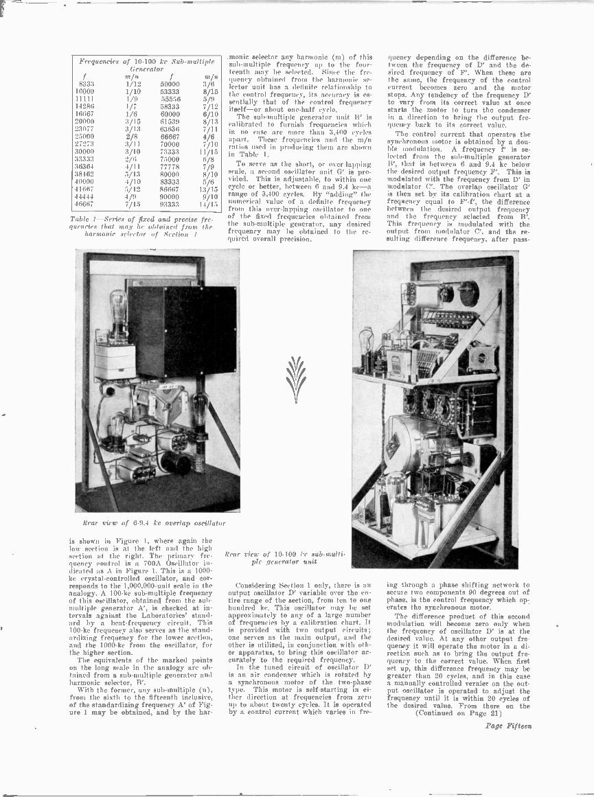
In the design of the new oscillator thecomplete range of 10 to 1,000 ke is divid-ed into two sub -ranges: one from 10 to100 ke, and the other from 100 to 1,000Ice, and except for the control oscillator,separate apparatus is employed for ob-taining frequencies in these two ranges.The two sections are essentially alike ex-cept for the frequency values. In the pho-tograph of the complete oscillator at thehead of this article, the two panels atthe left comprise the lower range sec-tion, and those at the right, the higherrange. A schematic of the separate piec-es of apparatus comprising the oscillator
SECTION IS100-1000 KILOCYCLES
F'±AF'-f'
6-9A KCOVERLAP
OSCILLATOR
F'-
10-100 KCOUTPUT
OSCILLATOR
LCCIRCUIT
100 KCFREQUENCYSTANDARD
FOR CHECKING
E'NO. 6A
CONTROLUNIT
PHASE SHIFTNETWORK
ANDMODULATOR
A1000 KC
CRYSTALCONTROLLEDOSCILLATOR
B
100 -1000 KCSUBMULTIPLEGENERATOR
ANDHARMONICSELECTOR
C
100-1000 KCMODULATOR
F+,6F
F±,6F-F
60-94 KCOVERLAP
OSC ILLATOR
100-1000 KCOUTPUT
OSCILLATOR
LCCIRCUIT
F
NO. 6ACONTROL
UNIT
PHASE SHIFTNETWORK
ANDMODULATOR
OUTPUT OUTPUTFREQUENCY FREQUENCY
F' F
Fig. 1-Block schematic of new oscillator showing division into two sections-one witha frequency range from 10 to 100 kc and one from. 100 to 1000 kc
Frequencies of 10-100 kc Sub -multipleGenerator
f min f min8333 1/12 50000 3/6
10000 1/10 53333 8/1511111 1/9 55556 5/914286 1/7 58333 7/1216667 1/6 60000 6/1020000 3/15 61539 8/1323077 3/13 63636 7/1125000 2/8 66667 4/627273 3/11 70000 7/1030000 3/10 73333 11/1533333 2/6 75000 6/836364 4/11 77778 7/938462 5/13 80000 8/1040000 4/10 83333 5/641667 5/12 86667 13/1544444 4/9 90000 9/1046667 7/15 93333 14/15
Table 1-Series of fixed and precise fre-quencies that may be obtained from the
harmonic selector of Section 1
.monic selector any harmonic (m) of thissub -multiple frequency up to the four-teenth may be selected. Since the fre-quency obtained front the harmonic se-lector unit has a definite relationship tothe control frequency, its accuracy is es-sentially that of the control frequencyitself-or about one-half cycle.
The sub -multiple generator unit B' iscalibrated to furnish frequencies whichin no case are more than 3,400 cyclesapart. These frequencies and the m/nratios used in producing them are shownin Table 1.
To serve as the short, or over -lappingscale, a second oscillator unit G' is pro-vided. This is adjustable, to within onecycle or better, between 6 and 9.4 ke-arange of 3,400 cycles. By "adding" thenumerical value of a definite frequencyfront this over -lapping oscillator to oneof the fixed frequencies obtained frontthe sub -multiple generator, any desiredfrequency may be obtained to the re-quired overall precision.
Rear view of 6-9.4 kc overlap oscillator
is shown in Figure 1, where again thelow section is at the left and the highsection at the right. The primary fre-quency control is a 700A Oscillator in-dicated as A in Figure 1. This is a 1000-kc crystal -controlled oscillator, and cor-responds to the 1,000,000 -unit scale in theanalogy. A 100-kc sub -multiple frequencyof this oscillator, obtained from the sub -multiple generator A', is checked at in-tervals against the Laboratories' stand-ard by a beat -frequency circuit. This100-kc frequency also serves as the stand-ardizing frequency for the lower section,and the 1000-kc from the oscillator, forthe higher section.
The equivalents of the marked pointson the long scale in the analogy are ob-tained from a sub -multiple generator andharmonic selector, B'.
With the former, any sub -multiple (n),from the sixth to the fifteenth inclusive,of the standardizing frequency A' of Fig-ure 1 may be obtained, and by the har-
Rear view of 10-100 ke sub -multi-ple generator unit
Considering Section 1 only, there is anoutput oscillator D' variable over the en-tire range of the section, from ten to onehundred ke. This oscillator may be setapproximately to any of a large numberof frequencies by a calibration chart. Itis provided with two output circuits;one serves as the main output, and theother is utilized, in conjunction with oth-er apparatus, to bring this oscillator ac-curately to the required frequency.
In the tuned circuit of oscillator D'is an air condenser which is rotated bya synchronous motor of the two-phasetype. This motor is self-starting in ei-ther direction at frequencies from zeroup to about twenty cycles. It is operatedby a control current which varies in fre-
queney depending on the difference be-tween the frequency of D' and the de-sired frequency of F'. When these arethe same, the frequency of the controlcurrent becomes zero and the motorstops. Any tendency of the frequency D'to vary from its correct value at oncestarts the motor to turn the condenserin a direction to bring the output fre-quency back to its correct value.
The control current that operates thesynchronous motor is obtained by a dou-ble modulation. A frequency f' is se-lected front the sub -multiple generatorB', that is between 6 and 9.4 kc belowthe desired output frequency F'. This ismodulated with the frequency from D' inmodulator C'. The overlap oscillator G'is then set by its calibration chart at afrequency equal to F' -f', the differencebetween the desired output frequencyand the frequency selected from B'.This frequency is modulated with theoutput from modulator C', and the re-sulting difference frequency, after pass-
ing through a phase shifting network tosecure two components 90 degrees out ofphase, is the control frequency which op-.crates the synchronous motor.
The difference product of this secondmodulation will become zero only whenthe frequency of oscillator D' is at thedesired value. At any other output fre-quency it will operate the motor in a di-rection such as to bring the output fre-quency to the correct value. When firstset up, this difference frequency may begreater than 20 cycles, and in this casea manually controlled vernier on the out-put oscillator is operated to adjust thefreqnency until it is within 20 cycles ofthe desired value. From there on the
(Continued on Page 21)
Page Fifteen

COLUMBIA GOES INTO SERVICE
The Columbia passing the Statue of Liberty in New York Harbor
The American flag was raised over the SS Columbia, on January 26th. Miss Eleanor Roosevelt was sponsor for the boat,which is a 39,935 -ton liner, and is now in the Panama -Pacific Line service, doing cruise service to Nas,:iu, Miami, and Havana.
ASSIGNMENTSMackay Radio-New York
Vessel Radio OfficerSS Ario-L. MasonSS Cherokee-J. Bamberg (Junior)SS Shawnee-S. Rosenberg (Junior)SS Cities Svc Empire-T. BurnsY. Doromar-Chas. ThomanSS W. R. Keever-E. TabakmanSS Manhattan-H. Burns (Third officer)SS Shawnee-P. Kimball (Junior)85 City of Dalhart-A. GyorfiSS Seminole-W. Weber (Junior)
Radiomarine Corp.-New YorkOriente-C.-D. ShortPan Bolivar-A. L. BergomSanta Elisa-W. P. PaschalNosa Queen-A. H. RoweMariana-M. DeValezOriente-S. SanchezCaracas-T. D. CaryCity of New York-L. R. ShawAmerican Shipper-J. H. SwallowBeaconstar-K. C. PetersonSanta Clara-C. J. MelvilleMadison-K. R. WilliamsDaylight-H. E. AndersonWalter Luckenbach-L. H. BrennanE. M. Clark-E. M. FullerMaine-H. G. WrightExilona-M. KamkeAcme-J. GatelyAmerican Banker-V. MadsenOriente-T. L. SiglinPaul H. Harwood-H. SudboroughPage Sixteen
Santa Cecilia-E. G. WashingtonSanta Cecilia-V. E. PentaColumbia-D. L. ShawColumbia-W. K. KochColumbia-I. MargolisGatun-H. SheerinWalter Jennings-J. GorbigCerro Azul-Ed. RoegerAllan Jackson-H. C. WagarAmerican Farmer-A. FinchSanta Maria-Everett PerryNosa Prince-J. R. HortonSanta Monica-Van Orstrand
RMCA-BostonTrawler Maine-J. Fish
Cities Svc Oklahoma-M. Wakefield (re-lief)
Cities Svc Oklahoma-A. Iodice (re-turned)
Mackay-BostonTrawler Plymouth-H. MacCalmonTrawler Dorchester-A. SoutherlandTrawler T. J. Whalen-C. KelleherShawmut-W. D. Thomas
States Steamship CompanyGeneral Pershing-Roy WelbonGeneral Pershing-Harry SchoolaeldGeneral Sherman-Karl SteinerGeneral Sherman-Ted ToppiGeneral Lee-Everett HenryGeneral Lee-James CrouseCalifornia-Ben CohenTexas-Roy WhittingtonMichigan-Dallas L. HughesIllinois-W. T. ShultrichNew York-Gordon BurnettWisconsin-Walter F. MeeWashington-John RobinsonPennsylvania-Kenneth HarrisKentucky-A. A. MarshOregon-Howard McMahonIowa-Rupert S. BeanSan Angelo-Frank CaldwellSan Anselmo-Earl GarrickSan Bernardino-Herbert OliverSan Clemente-David YoungbergSan Diego-Claude WarehamSan Domingo-Dewayne DuncanSan Felipe-M. R. Derby

Vacuum Tubes as High -Frequency Oscillators
(Continued from Page 6)travel from the cathode to the anodewithin the tube structure. This time, theso-called transit time, is very small inpresent day commercial types of powertubes, usually much less than one micro-second. Obviously at low frequenciesit can be neglected and, in fact, for ma-ny tubes it still plays a minor role ei-ther in determining the output and effi-ciency in the high -frequency range or inestablishing the limiting frequency foroscillations. When the frequency rangeof oscillation of a tube is extended by anadequate decrease in energy losses andby improvements in electrical design,transit time becomes a dominating fac-tor in the reduction of output power andefficiency and in establishing the limitingfrequency of oscillation.
This comes about in two ways. In thefirst place, the relative phase of the al-ternating grid and plate potentials forbest operation must be altered to com-pensate for the time required for theelectrons to travel from the region iuwhich the grid has its greatest effectupon their motion to the region inwhich their motion has the greatest ef-fect upon the plate current. The avail-able control over these phases is usual-ly insufficient to permit a realization ofthe optimum adjustment. In terms ofthe measured characteristics of the tube,the transconductance has become com-plex. But even with the optimum phaseadjustment the efficiency is reduced bylosses which occur because of the varia-tions in grid and) plate potentials duringthe transit time. Electrons arriving atthe plate will in general have velocitiesgreater than the velocity correspondingto the potential of the anode at the in-stant of their arrival. The excess ener-gy corresponding to the greater veloci-
Fig. 7-A tube for use at frequenciesup to 350 megacycles
150
140
130
120
110
100
90
t-
h 80
D 70a.
0 60
50
40
30
20
10
0
,............
\\
OUTPUT %. EFFICIENCY
\S.
"t.
\
60 70 80 90 100 110 120 130 140 150 160FREQUENCY IN MEGACYCLES PER SECOND
Fig. 6t-Output and efficiency as a function of frequency for the tubeshown in Fig. 5. A comparison of these curves with those shown in Fig. 1iltustratati the intprovemient obtained by taking account of those factors -
which become important at higl frequencies.
75
70
65
60
55
50
45 LI,
ce
40 ctz
35z
30 2_
25
20
15
10
5
0
60
W 50U
ILICC
40a.
z 30zW 20
LL
: 10
0
120
110
100
90
80
70
60
50
40
30
20
10
050 75 100 125 150 175 200 225 250 275 300 325 350 375 400
FREQUENCY IN MEGACYCLES PER SECOND
Fig. 8-Output and efficiency curves for 2 tubes of the type shown in Fig. 7.
Page Seventeen
170 180 190
Eb.750ft
ft
500 ftft ft....
Eb=1250
1000
750
500

Fig. 9-A typical push-pull circuit for use at ultra -high fit gat 'lett.). A circuitof this type was used to obtain the data shown in Figs. 8 and 11
ty is obtained from the oscillating cir-cuit and is dissipated at the plate in theform of heat. Again in terms of themeasured characteristics, the input con-ductance has been increased above itslow -frequency value.
The mechanism which enables electronsto take energy from the oscillatory cir-cuit in their passage across the tube isevident from a consideration of a some-what simplified ease as shown in Fig. 4.Assume that the anode is held at a con-stant potential of 100 volts, and that thegrid is held at 50 volts positive just longenough to allow an electron to come fromthe cathode to the grid plane (very nearone of the wires), where its velocity willcorrespond to a fall of 50 volts. The po-tential of the grid is then suddenlychanged to 50 volts negative. The elec-tron will then fall through an addition.al potential difference of 150 volts, ar-riving at the anode with a velocity cor-responding to 200 volts, producing justtwice as much heat as it would have donehad the grid potential not been changedduring the transit time. This added en-ergy must come from the source whichproduced the change in the grid poten-tial. In the actual case the change ingrid potential is not abrupt but a simi-lar loss occurs. This limits the usefulfrequency range of a tube to values forwhich the oscillation period is long com-pared to the electron transit time.Special Designs Required for Different
Ranges of High FrequenciesMost standard power tubes reach their
upper frequency limit of oscillation some -
Page Eighteen
where in the 10- to 100 -megacycle fre-quency range. For frequencies above this,specially designed tubes are required.The frequency range in which a given de-sign is near the optimum is limited.Therefore, there is a succession of tubes,each rated for a band of frequencies.Characteristics such as a high mutualconductance and a sharp cut-off whichmake a tube a good oscillator at lowfrequencies, while still of importanceat ultra -high frequencies, are apt to besecondary to the special frequency re-quirements. Although some progress hasbeen made in the modification of con-ventionally designed water-cooled tubes
30
25
I- 20
Z
a.a.
8 to
5
0200 250
for use above 100 megacycles, more at-tention has so far been given to the de-velopment of radiation -cooled tubes forthis frequency range.
A departure from conventional de-sign with increasing frequency is illus-trated by a radiation -cooled tube de.seri bed by Me Arthur and Spitzer inwhich the ratio of the plate diameter to
Fig. 10 --This tube will oscillate at fre-quencies up to 740 megacycles. Note theabsence of the usual press and the ex-
tremely small size of the elements
the plate length is much larger than forthe conventional tube. Radiating fins arcemployed to compensate for the decreasein heat radiating ability of the platewhich would otherwise occur because ofits short length. In Fig. 5 is shown a pho-tograph of this tube. It will be notedthat the tube electrodes are supported di-rectly from their leads. The complete ab-sence of auxiliary supporting memberseither of metal or of insulating materialand the large size of leads reduce radia-tion, eddy current, and conduction cur-rent losses. That portion of the inter -electrode capacitances due to the sup-porting structure is also made small bythis method of support.
The inter -electrode capacitances aregiven below, together with the corre-sponding values for the type 242A tube,which has the same plate dissipation
(Continued on Page 20)
-----...... ----1.,....Eb=400EFFICIENCY ..
----- -...s.,. 300....
-- ......
400 s'OUTPUT
3° "--2N
......
...
300 350 400 450 500 550 600FREQUENCY IN MEGACYCLES PER SECOND
650 700
30
25
z200
a
15
z
i0 5LL
0750
Fig. 11-Output and cfficency curves for 2 tubes of the type shown in Fig. 10

THE NEW HIGH FIDELITY"
BROADCAST TRANSMITTERTYPE 5-C
A DE LUXE 5000 WATT EQUIPMENT FOR1/2.5, 1/5 AND 5 K.W. BROADCASTING STATIONS
FEATURING:1 High Fidelity Performance
2 Low Operating Cost
3 Complete A. C. Operation
4 Ingenious Hum Compensation
6 Cathode Ray Indicator for Modulation
7 Complete Harmonic Suppression
8 Automatic Overload Protection
9 Mycalex and Isolantite Insulation5 Safety and Convenience of Operation 10 Strikingly Attractive Modern Design
THE STANDARD OF MODERN BROADCAST PERFORMANCE
RCA MANUFACTURING COMPANY, INC.CAMDEN, N. J. "RADIO HEADQUARTERS"
Page Nineteen

Vacuum Tubes as High -
Frequency Oscillators(Continued from Page 18)
rating but is designed for use at lowerfrequencies:
High FrequencyTube 242A
Plate to grid ____3 µµf 13.0 AlifGrid to filament ___2 Aulf 6.5 tutfPlate to filament__] µµf 4.0 AOThe decrease in capacitance by a factorof approximately 4 makes possible amuch greater improvement in perform -
watts with substantially the same plateloss. This strikingly illustrates the im-provement obtained by taking into ac-count the factors which become impor-tant in the high -frequency range.Transit Time Becomes More Important
In extending the frequency range to300 megacycles the importance of elec-tron transit time becomes relativelygreater. It must be kept as low as pos-sible even at the expense of relativelyhigher interelectrode capacitances. Inthe tube just described for the frequencyrange around, 100 megacycles the reverseprocedure is followed in order to make
Fig. 1$-These reiaisi al a further extensi,,,, in design according tothe principles under dismission. 77,, smaller one will sc-o al 1200 megacycles
/55 I' See011d
ance in the 60- to 150 -megacycle per -sec-ond frequency range than the corres-ponding degradation in performance dueto the lower mutual conductance and theincreased electron transit time result-ing from the increased spacing. Thematerial increase in plate impedancemakes it necessary to employ an anodepotential approximately twice as greatwith the high -frequency tube.
Output and efficiency curves are shownin Fig. 6. (For the sake of uniformity,curves taken from published papers have,in most cases, been reilrt wn.) The particular shape of the output curve is dueto the manner in which the applied an-ode potential was reduced with increas-ing frequency to minimize the danger oftube failure from the increased energylosses which occur at high frequencies.The limiting frequency as set by theinter -electrode capacitances and lead inductances is given by the authors as 230megacycles. An extension of the effi-ciency curve to higher values indicatesthat the tube will probably fail to oscil-late before this limit is reached. Fromthis it call be inferred that the decreasein efficiency in the range from 150 to200 megacycles is due largely to the ef-fect of the relatively large transit time,since the authors' method of arriving atthe output by taking the difference between the measured input and the meas-ured plate losses includes circuit andlead losses as a part of the output. Acomparison of the data of Fig. 1 andFig. 6 shows that at 100 megacycles theoutput of the type 242A tube is 2 wattsand the corresponding output of thehigh -frequency tube is approximately 86
Page Twenty
the inter -electrode capacitances as smallas possible, transit times are increased.Fay and Samuel in a recent paper pre-
sented before the International ScientificRadio Union (U. R. S. I.) describe a tubedesigned for use at 300 megacycleswhich well illustrates this point. The tubeis shown in Fig. 7. It differs from theone previously discussed in the closespacings between elements, particularlybetween the grid and filament. The leadlength is further decreased and lead di-ameter made considerably larger in or-der to increase lead inductance and re-sistance. The inter -electrode capacit:nu-es are:Plate to grid 2.5 µµfGrid to filament 2.0 ItAtfPlate to filament 0.67 '1;4
While these capacitances are substan-tially the same as for the tube shown illFig. 5, the limiting frequency, as set by
ANODE
CATHODE
GR
Fig. 14-A sectional view of the triodedeveloped by Thompson and Rose
circuit resonance is somewhat beyond400 megacycles as contrasted with 230megacycles for the other tube. This isdue, primarily, to the material decreasein lead inductance. The decreased lossesresulting front the minimized transit timemore then compensate for the increasedcircuit loss resulting from the required
1
Fig. 13-Receiving tubes of extremely small dimensions. A conventional receitittg type tube is shown at the right for comparison.

higher charging currents to the inter-electrodo capacitances. Its mutual con-ductance of 2200 micro -ohms and thesharp cut-off shown by the static char-acteristics indicate that those electricalcharacteristics which are important forefficient oscillators in the low -frequencyrange have not been, sacrified in meetingthe requirements of 300 -megacycle opera-tion.
Output and efficiency curves for thistube are shown in Fig. 8. These data arefor two tubes operated in the push-pullcircuit shown in Fig. 9. The output shownrepresents only useful power, since it isthe photometrically measured power con-sumed in a lamp load. It will be notedthat, whereas the maximum output at100 megacycles is 55 watts per tube andthe efficiency 50 per cent., correspondingroughly to the 86 watts output. at 47 percent. efficiency for the tube of Fig. 5,the output at 200 megacycles is 34 wattsat 33 per cent. efficiency as compared toless than 10 watts at an efficiency of onlya few per cent. for the other tube. At300 megacycles the higher frequency tubegives an output of 13 watts, while thetube of Fig. 5 no longer oscillates. Thisdifference in behavior is due primarilyto the decreases in transit time and in cir-cuit losses, and to the more nearly opti-mum ratio existing between the inter -electrode capacitances. It is due to aconsiderably less extent to the increasein the frequency limit set by circuit res-onance.
(To be Continued in Next Issue)
An Adjustable Oscillatorof High Precision
(Continued from Page 15)motor will automatically hold it at thatvalue.
The apparatus of Section 2 is identicalin function to Section 1. Because of thehigher range, however-running from 100to 1000 kc-the overlap oscillator has arange of 34,000 cycles, or from 60 to 94kc. It can be set by its calibration chartto anywhere within ten or fifteen cyclesof the desired value. A frequency be-tween sixty and ninety-four ke, however,is within the range of Section 1, and sowhere greater precision than ten or fif-teen cycles is required, Section 1 is substituted for the overlap oscillator of Sec-tion 2. The switching by which this isdone is indicated in Figure 1. Since theoutput of Section 1 is accurate to with-in one or one and one-half cycles, theoutput of Section 2 will be held to prac-tically a like accuracy.
The principle of operation adopted forthis oscillator has quite appreciably re-duced its cost by making it unnecessaryto employ filters, which are generally re-quired to eliminate the unwanted prod-ucts of modulation. With this oscillatorthe two frequencies modulated are in ev-ery case quite close in value, and of atleast moderately high frequency. As aresult, there is a wide spread betweenthe difference frequency and the othermodulation products. The spread is sogreat that the necessary discriminationis obtained in the modulator output cir-cuit without tuning. An example willillustrate this feature and, in addition,will show the general method of operation.
Assume a frequency of 92,105 cycles isdesired. From Figure 2 it is quickly seenthat the frequency obtainable from B'which will be less than 92,105 by 6 to 9.4kc is 83,333 cycles. The output oscillator,on the other hand, can be set from its
(Continued on Page 12)
Added Features. Among
In Stock --ImmediateDelivery
The New
PATTERSON PR -12r R.12them are: 2 stage of Pre -Selection -3 1. P. Stages-Accurate logging band spread.
NET DELIVERED PRICESComplete with tubes, 10%2" dynamic speaker, etc. (Absolutely nothing else to buy!)PR -]2 Crackle cabinet without crys- PR -12 Console with crystal 105.55
tal $82.00 Chassis also availablePEAK Pre -Selector 19.80PR -12 Crackle cabinet 'with crystal 87.90 PATTERSON Pre Selector 17.64
PR -l2 Console without crystal 99.65 SARGENT Pre -Selector 14.75NEW "MARINE" 100 Watt Phone-C.W. XMITTER.
Many exclusive features including Visual distortion Indicator -Modulation Percent-age Indicator (Built-in Cathode Ray Oscilloscope). Send stamp for descriptivefolder and details.SHIPPED PREPAID if full purchase price accompanies your order. Send
for our bulletin "Amateur Transmitter" whichlists and describes "Everything for the Ham."
L. I. MARINVer ELECTRIC COA163-18 Jamaica Ave.
W2GOT-W2GRQ---Dept. C3 JAMAICA, N. Y.
('Nile Address "ELECMARINE NEW YORK"4=.Mr..111..411111...4M.M.0.11.M004MkOOMP0414.4=1414M.04=10,
Sending is EASYWith ti c Genuine Martin No, 6
New VIBROPLEXReg. Trade Marks: Vihroplex ; Bug;
Lightning BugIN COLORS -):Iae. Green. Red
The smoothest, easiest -working hug onthe market. Easy to learn. Easy to oper-ate. Makes sending ea°y.
MARTIN JUNIOR
$10
Improved MARTIN Vibroplex
Black or f217Colored sW
Nickel- 4219Plated /PA
Special Martin Radio Bug-Extra large.Specially Constructed Contact points fordirect use without relayBlack or colors. $25
Why hi misled by offerr of anything but thc GEN-UINE MARTIN VIBROPLEX? MARTIN JUNIORembodies all standard Martin teaturcs and quality.Like Improved Martin but furnished on 234 poundblack japanned base, Remit by Money Order or Reg-istered Mall.
THE VIBROPLEX COMPANY, Inc.825 Broadway, New York City
Cable Address: "VIBROPLEX" New YorkM=INMIMP.1.1=1,0.04§M 44M104=0.11
CARDWELLTRANSMITTING
CONDENSERS"THE STANDARD OF COMPARISON"
For Over a Decade-Send for Literature-
THE ALLEN D. CARDWELL MFG.CORP.
Prospect and Pearl Sts.,Brooklyn, N. Y.
Page Twenty-one

COMMERCIALRADIO GEAR
The new 1935 ALLIED Ra-dio Catalog, which is your,for the asking, offers a com-plete listing of Trarssmittingand Receiving Equipment.Covers professional ShortWave Receivers, transmit-ting tubes, Keys, relays,phones, meters, S. W. parts.Az. Write for this valuabbook, as well as for informa-tion covering C oturh-Brengte professional equipment
such as oscilloscopes, beat -note oscillators.vacuum tube volt -ohmmeters ---Bliley "A"and "AT" cut xtals for commercial fry-luencies-the new RCA-ACR 136 Communi-cations receiver, etc.
Send for Our Catalog
Allied Radio_CORPORATION833 W. Jackson Boulevard
CHICAGO, Ill. Dept. CQ
New--DUCOS--NewPAPER CONDENSERIN NEAT BAKELITECONTAINERSCOST NO MORE THANCHEAP PAPER CONDENSERS
Patents )'ending
OIL IMPREGNATED600V -1000V -1500V
Guaranteed Two Years
Send for Free Catalog-Sales andJobber Territory Open
lfarntfacturcd by
Dumont Electric Co.453C Broome St., New York City
SUBSCRIBE NOW!
You who have been fol-lowing our b o o k
should know better than oth-ers that an issue lost leavessomething to be wanted.NOW is the time to makesure of receiving every issue.
Send $2.00 at once to"Commercial Radio"
7 West 44th St.
New York, N. Y.
NEW APPARATUSNew 75 -Watt Aircraft Trans-
mitter Weighs 75 PoundsA NEW long distance telegraph trans-
mitter weighing only 15 pounds anddelivering a nominal 75 watts of continu-ous wave radio frequency power to theantenna, is announced by the radio di-vision of Westinghouse Electric & Man-ufacturing Company, Chicopee Falls,Mass. The new CH transmitter repre-sents 5 watts for each pound of trans-mitter unit, and operates on frequenciesranging front 333 kilocycles up to 10000kilocycles by means of plug-in coil as-semblies. This provides for operationwith marine stations including ships atsea as well as operation on the aviationcommunication bands.
The set operates from the 12 volt bat-tery system of the plane through dyna-motor. The relatively low plate supplyvoltage of 500 utilized for a transmitterof this power, as compared with 1000volts usually employed, is a decided ad-vantage for reliable operation under va-t ions climatic conditions.
The dynamotor is purposely designedfor aircraft service. It is unusuallylight in weight although ruggedness hasnot been sacrificed. The use of magne-sium alloy castings combined with care-ful design has resulted in a machine of131%t pounds weight capable of deliver-ing 150 watts of 500 volt power to the
transmitter. This represents a factor o11 watts per pound of dynamotor.
In brief, specifications of the nesttransmitter are:
Power Output -75 watts nominalType of Signals-Continuous Wave
TelegraphCoil Systems:
2700-3450 kilocycles3450 -4420 -kilocycles4420-5890 kilocycles5890-741(1 kilocycles7410-8620 kilocycles8620-9700 kilocycles500 kilocycles with external anten-
na coilkilocycles with external atnten-
na coilPower Supply: 12 to 14 volts D.C.
through a 500 volt dynamotorTube Complement:
1-UX-210 as Master Oscillator4-UX-210's as Power Amplifier
Weights: lbs.Transmitter Unit with one set ofcoils and shock absorbing base 15Operator's Control Unit 1
Dynamotor 13%Flameproof Telegraph Key
FOR SERVICINGA new test oscillator specifically de-
signed to meet the servicing require-ments of modern all -wave radio receiv-ers has been announced by the WestonElectrical Instrument Corporation, New-ark, N. J. It has a frequency range from100 kilocycles to 22 megacycles, and aspecial attenuator system which makespossible an approximate output of onemicrovolt. This low minimum signal isa factor of increasing importance in ser-vicing operations, as it permits align-ment of receivers equipped with auto-matic volume control below the a.v.c.level.
Constant output over the wide frequen-cy range is provided by means of sixindividual coils, which are plugged intoa doubly shielded compartment for op-eration on each of six frequency bands.The use of plug-in coils eliminatesswitching leads, thus reducing electro-magnetic and electro-static fields withinthe oscillator. Complete shielding of thecoil in use, in addition to over-all shield-ing, prevents interaction and resonanceeffects with coils not in use on otherparts of the circuit.
Output of the Model 692 oscillatormay be attenuated from a 0.2 -volt max-imum to approximately one microvolt, aconstant impedance of 200 ohms beingmaintained at the output jack pins thru-out this attenuator range. Thus the at-tenuator setting does not affect inputimpedance at the antenna and groundposts of the receiver and alignment maybe carried without upsetting the firsttuned circuit of the receiver by subse-quent changes in attenuator adjustment.All attenuation is done ahead of theconstant output resistance, so that in-accuracies resulting from the commonpractice of short-circuiting the outputposts to obtain a signal of low value areeliminated.
The unit is equipped with two Type30 tubes, one of which operates in aseparate modulator circuit to provideconstant internal modulation of 50%at all frequencies. Tests have shownthat only an independent modulator cir-cuit will provide this constant modula-tion on high frequency bands. A switchcutting out internal modulation per-mits the unit to be used as a pure r.f.oscillator for tuning receivers by theHiss or Tuning Meter method. In addi-tion, two pin jacks are provided on thepanel for introducing external modula-tion when desired. This feature is par-ticularly useful for making fidelity mea-surements on receivers by means of con-stant phonograph records now available.
Page Twenty-ttco

CLASSIFIED ADSCOMMERCIAL L41)1() will accept classified adver-
tising at the special rate of five cents per word.Remittance in full must accompany copy. Closing date
for classified advertisements is the 15th of the month pre-ceding publication date.
FOR SALE -Radio Model Vibroplex, heavy contacts,$10.50. Like new. Guaranteed. John Morgan, 54 'lard
ing Drive, Glen Oaks, Rye, N. V.
ONE NEW SET Van Nostrand Mathematic books:Arith-metk, Algebra, Trigonometry, Calculus and How
Study; 4 vols. $3.50, list price $7.00. LO., care CommercialRadio, 7 W. 44th St., N. V. City.
!Pr The 7-P0 I NTMICROPHONEACCLAIMED SUPERIOR!
"Send 3 more microphones" ... "Best we've everhad"... "Dropped 20 feet. still good as ever"...Typical comments of engineers who are using theAmperite SR -60 Velocity Microphone. (Proof onrequest): Because of its wider area of coverage,the SR -80 does the work of 3 ordinary mikes. Ithas 7 points of advantage which give you thegreatest value in velocity microphones availabletoday, Conviace yourself. Write for IllustratedBulletin E-3.
AMPER1T£ Grporation
Army & Navy Surplus
Relay and Jac s combination, 350 ohms,volt, $1.00
1 N DUCTION COILS, Battery TelephoneType $1.26
NEW -Edison Storage Battery Type BB-C 10 volt, 37 amp., contain.: 7 cells. Com-plete in steel portable case $10.00
Nlagnaatox anti -noise microphone, good forhome broadcasting $1.50
CONDENSERS, Mica, op. volts 12,600cap. .004
Dubilier, new $9.50Dubilier, uaed 6.00Wireless spec., new 6.00Wheless spec., used 3.60Condenser, Dubilicr, mica, volts 40,000,
cap. .0012-.001-.0006 or .003 12.00Condenser, Dubilier, mica, op. volts
8,500 cap. .004 7.00Conden.:ers, Dubilier, mica, op. volts
8,600 capacity .0004 mfd. 7.00t 'ondenset s, Murdock .002 mfd. 6000
volt 1.50
Anti -Capacity Switcher. W. E. 12 anu 14Terminal..., all with Platinum Contacts.value $3.50 each. Our price ..$1.25 each
MOTOR GENERATORS120 d.t , Ilti t,t 220 a.e., 500 cycle
250 watt $35.00120 d.c , 110 or 220 ac., 500 cycle
500 watt $60.00 to $80.00120 d.c., 110 or 220 a.c., 500 cycle
1 kw. $80.00 to $110.00120 d. c , 110 or 220 a.c., 600 cycle
2 kw. $60.00 to $170.00120 d. c.. 110 or 220 a. c., 600 cycle
5 kw. $96.00 to $260.00120 d.c., to 20 d.c.. 2 kw 70.00120 d.c., to 400 d.c.. 2 kw. 65.00120 d.c.. to 600 d.c., 2 kw. 75.00
You Know theQuality
SPECIALCan be used with the new Vacuum Con-
tact when operated on 45 volts. WesternElectric Signal "Drops," 1000 ohm, type.D-12 $2.00
U.S. Navy OxidizedBrass RunningLights, 16 incheshigh overall -12 lbs.Either red or green.$7.60 each or $12.00per pair. Kerosenetype, easily con-
verted to electric.
GENERATORS110 volt a. c. 900 cycle self-excited
200 watts $12.00165 volt a.c. 600 cycle self-excited
250 watts 17.00110 volt a.c. 600 cycle, self-excited
250 watts 08.001500 volt d.c. 660 mills, 1 kw., Esco
1750 r.p.m. 50.00240 volt 500 cycle. self-excited 2500
r.p.m. 250 watt, (retro hand drive) 28.00120 volt d.c., 5 kw. 65.00120 volt d.c., 20 kw. 126.00000 volt d.c. 2 kw. 50.00220 volt a.c.. 500 cycle 1 kw 60.00220 volt a c., 500 cycle 2 kw. 70.0012 volt d.c., 60 amp. 18.0012 volt d.c.. 33 amp. 9.50
Postage and deposit of 20 per
cent. required on C. 0. D. orders
No orders shipped for less than $1
WE 1)0 NOT ISSUE CATALOGS
JOHN REARDONSURPLUS SPECIALIST
725 Longacre Bldg.1457 Broadway
NEW YORK, N. Y.
Baldwin Headphones. Genuine Mica Dia-phiagni 2000 ohm. Regular $15 val. $3.58
VOLTMETERS, D. C. portable newWeston model 45, 3 scale 0-3-15-160 guar-anteed 1-4 of 1 per cent accurate ..$50.00Ammeters, D.C., portable, new Weston
model 46; 3 scale 04-546-150 with 3scale external shunt and leads 1-4 of 1per cent accurate $40.00
EDISON STORAGEBATTERIES
All Types1.2 Volts per Cell
A-1 Amps. 175 per cell $4.60A-6 Amps. 225. per cell 6.00A-8 Amps. 300. per cell 6.0011-4 Amps. 90. per cell 4.60114 Amps. 11. per cell 2.001.-40 Aanps. 25. per cell 2.60.1-3 Attrpr. 3/. per cell 440
Ampere hourmete r. San-gamo. batterycharge a n ddischarge, typeMS 0-500 scale.capacity 1 6
.$12.00
NAVY AIRCRAFT DYNAMOTOR. Gcn.Eh,. new 24-1000 volts, 1 amp, extendedshaft with pulley, can be driven by motoror ',lonelier. giving 24 volts output fortilanalst and 1000 volts for plate or drivenby its own input of 24 volts. Value $250.00.I lur special price. $60.00
DYNAMOTORS24-750 volt Gen. Electric 200 mills..$30.0024-1000 Gen. Elec. 1000 mills 60.0024-4500 Gen. Elcc. 2% kw. output 105.0012-300 volt 80 mills 20.0012-750 volt 200 mills 33.0032-350 volt SO mills 10.0032-300 volt 60 mills 8.00Dynamotor Armatures, General Electric
triple commutators. d.c. 24-1500 v 14.00

Your Subscription s$
BY SENDINGALL YOUR MAGAZINESUBSCRIPTIONS IN ATONE TIME TO US YOU
SAVE BOTH TIMEAND MONEY !
SUBSCRIPTIONSARE IMMEDIATELY
CLEARED BY USTO THE PUBLISHERSOF YOUR FAVORITE
MAGAZINES
('tubPrice Alone
ClubPrice Alone
$2.25 Radio News $2.50 Commercial Radio $2.002.00 Radio Craft 2.50 Electronics 3.001.75 Radio Engineering 2.00 Broadcasting 3.000.25 Proceedings of the Institute Radio 3.00
of Radio Engineers 10.00 QST 2.50R/9 1.50
Electrical Engineering Radio Music Merchant 2.00General Electric Review 3.00 Radio & Electric Sales 1.00
Electric Journal 2.00 Radio World 6.00Bell System Tech.Tournal 1.50 Radio Retailing 2.00
Club Price
SystemPopular Mechanics
Regular
$3.002.25
GENERAL MAGAZINESClub Price Regular
American Magazine $2.50American Boy 1.00
Club Price
Good HousekeepingJudge
Regular
$2.501.50
$1.35 Popular Science 1.50 Aero Digest 3.00 Ladies Home Journal 1.00
2.50
2.25
Review of ReviewsRed Book
3.00
2.50 $3.75AdventureAtlantic MonthlyBoys' Life
3.004.001.00
LibertyLifeMcCall's
2.001.351.00
3.75 Scribners 4.00 1.75 Colliers Weekly 2.00 Motor Boating 3.002.25 Science & Mechanics 2.50 2.75 Current History 3.00 National Geographic 3.50
3.75 Scientific American 4.00 Delinestor 1.00Nations BusinessPictorial Review
3.001.00Saturday Evening Post 2.00 Esquire 5.00 1.85 Today 2.00
Cosmopolitan 2.50 2.25 Field & Stream 2.50 True Story 1.50
C. / 1.11M. 14MIr 4M OM. 4111111 NM. 14/M 1Ml. .41.10. NMI.INNIN14111
Iwrite us. We hare a limited number of catalogues of magazine subscription prices and will send for the asking whilethey last.
MID441=11.1
DO NOT SEND CASH. SEND CHECK OR MONEY ORDER
WRSCRIPTION DEPARTMENT
CQ MAGAZINE COMPANY, 7 WEST 44TH ST., NEW YORK CITY
If there are any magazines on which you wish a special quotation not listed above, or any group of magazines-