a pencil-and-paper method for elucidating halide double ...directionality (s and p character) and...
TRANSCRIPT

ChemicalScience
EDGE ARTICLE
A pencil-and-pap
aDepartment of Chemistry, Stanford Unive
[email protected] of Physics, University of Bayreuth,cStanford Institute for Materials and Ener
Laboratory, Menlo Park, California 94025,
† Electronic supplementary informationsupplementary gures, detailed groupp-bonding bands. See DOI: 10.1039/c9sc0
Cite this: Chem. Sci., 2019, 10, 11041
All publication charges for this articlehave been paid for by the Royal Societyof Chemistry
Received 29th June 2019Accepted 30th September 2019
DOI: 10.1039/c9sc03219c
rsc.li/chemical-science
This journal is © The Royal Society of C
er method for elucidating halidedouble perovskite band structures†
Adam H. Slavney, a Bridget A. Connor, a Linn Leppertb
and Hemamala I. Karunadasa *ac
Halide double perovskites are an important emerging alternative to lead-halide perovskites in a variety of
optoelectronic applications. Compared to ABX3 single perovskites (A ¼ monovalent cation, X ¼ halide),
A2BB0X6 double perovskites exhibit a wider array of compositions and electronic structures, promising
finer control over physical and electronic properties through synthetic design. However, a clear
understanding of how chemical composition dictates the electronic structures of this large family of
materials is still lacking. Herein, we develop a qualitative Linear Combination of Atomic Orbitals (LCAO)
model that describes the full range of band structures for double perovskites. Our simple model allows
for a direct connection between the inherently local bonding between atoms in the double perovskite
and the resulting delocalized bands of the solid. In particular, we show how bands in halide double
perovskites originate from the molecular orbitals of metal–hexahalide coordination complexes and
describe how these molecular orbitals vary within a band. Our results provide both an enhanced
understanding of known perovskite compositions and predictive power for identifying new compositions
with targeted properties. We present a table, which permits the position of the conduction band
minimum and valence band maximum in most double perovskites to be immediately determined from
the frontier atomic orbitals of the B-site metals. Using purely qualitative arguments based on orbital
symmetries and their relative energies, the direct/indirect nature of the bandgap of almost all halide
double perovskites can thus be correctly predicted. We hope that this theory provides an intuitive
understanding of halide double perovskite band structures and enables lessons from molecular
chemistry to be applied to these extended solids.
1. Introduction
Perovskites encompass a vast structural and compositionaldiversity featuring 0-, 1-, 2-, and 3-dimensional lattices incor-porating s-, p-, d-, and f-block metals. This diversity is reectedin the widely varying properties of perovskites, which have beenstudied as superconductors,1 catalysts,2 rare-earth phosphorhosts,3 and conductors for lithium ions,4 oxide ions,5 andprotons.6 The most-studied perovskites are oxides. However,halide perovskites have recently attracted a resurgence ofinterest. This is largely due to the outstanding photovoltaicperformance of the lead-halide 3D perovskites (Fig. 1A), whichhave afforded solar cells with power conversion efficienciesexceeding 24% 7 only 10 years since their initial demonstration.8
rsity, Stanford, CA 94305, USA. E-mail:
Bayreuth, 95440, Germany
gy Sciences, SLAC National Accelerator
USA
(ESI) available: Computation methods,theoretical analysis, and analysis of3219c
hemistry 2019
However, the inherent instability, high toxicity, and environ-mental mobility of these water-soluble Pb2+ salts9,10 have insti-gated a large effort to identify other compositions that possesssimilar electronic properties.
The recent revival of interest in halide double perovskites(elpasolites),11–13 which have been known since the 1880s,14 hasbeen primarily motivated by the desire to replicate the elec-tronic structures of the lead-halide perovskites15 in alternativecompositions. We have been deeply invested in this effort,primarily through the introduction of double perovskites aspotential solar absorbers11 and the synthesis of targeted newcompositions for obtaining suitable bandgaps for sunlightabsorption.16,17 The AI
2BB0X6 double perovskites (A ¼ mono-valent cation, X ¼ halide; Fig. 1B) have the same connectivity asthe ABIIX3 single perovskites but divide the formally 2+ charge atthe octahedral site (the B site) unevenly over two sites, allowingfor the incorporation of metals with oxidation states from +1 to+4. This uneven division is advantageous because almost everyelement has a stable oxidation state between +1 and +4 allowinga wider variety of metals to be incorporated. The compositionalexibility of double perovskites leads to an incredible degree ofcomplexity and diversity in their electronic structures. In these
Chem. Sci., 2019, 10, 11041–11053 | 11041
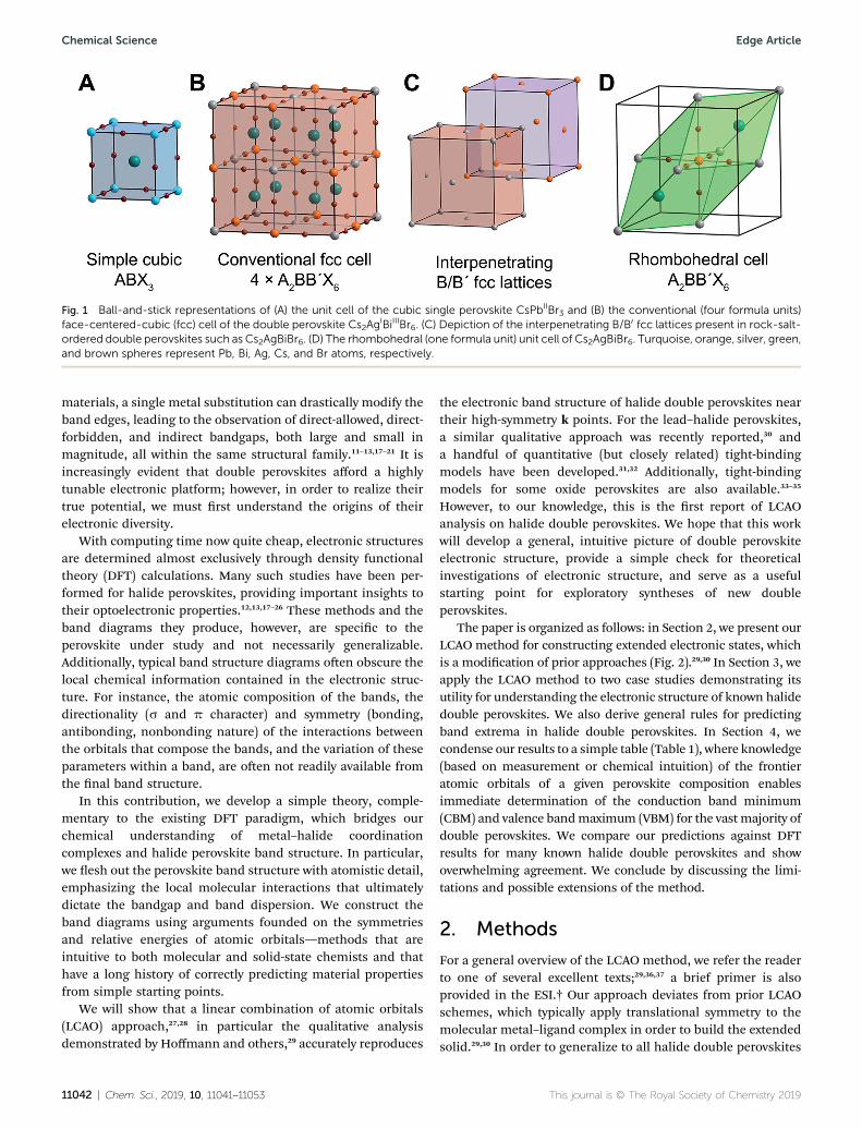
Fig. 1 Ball-and-stick representations of (A) the unit cell of the cubic single perovskite CsPbIIBr3 and (B) the conventional (four formula units)face-centered-cubic (fcc) cell of the double perovskite Cs2Ag
IBiIIIBr6. (C) Depiction of the interpenetrating B/B0 fcc lattices present in rock-salt-ordered double perovskites such as Cs2AgBiBr6. (D) The rhombohedral (one formula unit) unit cell of Cs2AgBiBr6. Turquoise, orange, silver, green,and brown spheres represent Pb, Bi, Ag, Cs, and Br atoms, respectively.
Chemical Science Edge Article
materials, a single metal substitution can drastically modify theband edges, leading to the observation of direct-allowed, direct-forbidden, and indirect bandgaps, both large and small inmagnitude, all within the same structural family.11–13,17–21 It isincreasingly evident that double perovskites afford a highlytunable electronic platform; however, in order to realize theirtrue potential, we must rst understand the origins of theirelectronic diversity.
With computing time now quite cheap, electronic structuresare determined almost exclusively through density functionaltheory (DFT) calculations. Many such studies have been per-formed for halide perovskites, providing important insights totheir optoelectronic properties.12,13,17–26 These methods and theband diagrams they produce, however, are specic to theperovskite under study and not necessarily generalizable.Additionally, typical band structure diagrams oen obscure thelocal chemical information contained in the electronic struc-ture. For instance, the atomic composition of the bands, thedirectionality (s and p character) and symmetry (bonding,antibonding, nonbonding nature) of the interactions betweenthe orbitals that compose the bands, and the variation of theseparameters within a band, are oen not readily available fromthe nal band structure.
In this contribution, we develop a simple theory, comple-mentary to the existing DFT paradigm, which bridges ourchemical understanding of metal–halide coordinationcomplexes and halide perovskite band structure. In particular,we esh out the perovskite band structure with atomistic detail,emphasizing the local molecular interactions that ultimatelydictate the bandgap and band dispersion. We construct theband diagrams using arguments founded on the symmetriesand relative energies of atomic orbitals—methods that areintuitive to both molecular and solid-state chemists and thathave a long history of correctly predicting material propertiesfrom simple starting points.
We will show that a linear combination of atomic orbitals(LCAO) approach,27,28 in particular the qualitative analysisdemonstrated by Hoffmann and others,29 accurately reproduces
11042 | Chem. Sci., 2019, 10, 11041–11053
the electronic band structure of halide double perovskites neartheir high-symmetry k points. For the lead–halide perovskites,a similar qualitative approach was recently reported,30 anda handful of quantitative (but closely related) tight-bindingmodels have been developed.31,32 Additionally, tight-bindingmodels for some oxide perovskites are also available.33–35
However, to our knowledge, this is the rst report of LCAOanalysis on halide double perovskites. We hope that this workwill develop a general, intuitive picture of double perovskiteelectronic structure, provide a simple check for theoreticalinvestigations of electronic structure, and serve as a usefulstarting point for exploratory syntheses of new doubleperovskites.
The paper is organized as follows: in Section 2, we present ourLCAO method for constructing extended electronic states, whichis a modication of prior approaches (Fig. 2).29,30 In Section 3, weapply the LCAO method to two case studies demonstrating itsutility for understanding the electronic structure of known halidedouble perovskites. We also derive general rules for predictingband extrema in halide double perovskites. In Section 4, wecondense our results to a simple table (Table 1), where knowledge(based on measurement or chemical intuition) of the frontieratomic orbitals of a given perovskite composition enablesimmediate determination of the conduction band minimum(CBM) and valence bandmaximum (VBM) for the vast majority ofdouble perovskites. We compare our predictions against DFTresults for many known halide double perovskites and showoverwhelming agreement. We conclude by discussing the limi-tations and possible extensions of the method.
2. Methods
For a general overview of the LCAO method, we refer the readerto one of several excellent texts;29,36,37 a brief primer is alsoprovided in the ESI.† Our approach deviates from prior LCAOschemes, which typically apply translational symmetry to themolecular metal–ligand complex in order to build the extendedsolid.29,30 In order to generalize to all halide double perovskites
This journal is © The Royal Society of Chemistry 2019
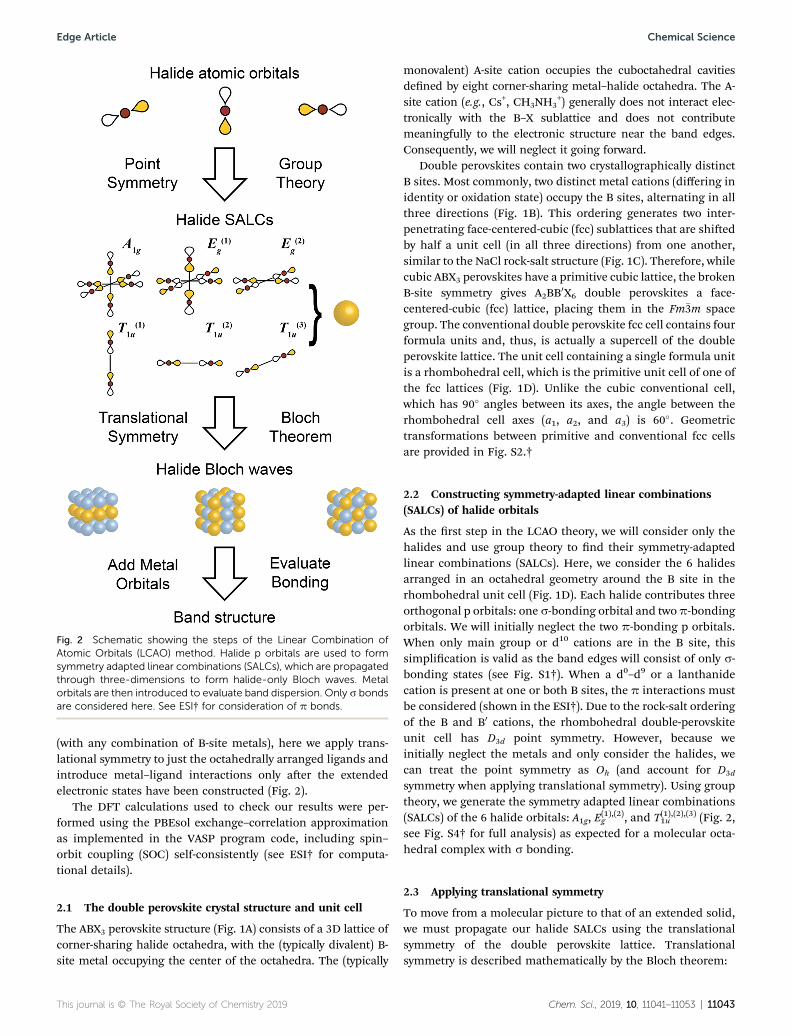
Fig. 2 Schematic showing the steps of the Linear Combination ofAtomic Orbitals (LCAO) method. Halide p orbitals are used to formsymmetry adapted linear combinations (SALCs), which are propagatedthrough three-dimensions to form halide-only Bloch waves. Metalorbitals are then introduced to evaluate band dispersion. Only s bondsare considered here. See ESI† for consideration of p bonds.
Edge Article Chemical Science
(with any combination of B-site metals), here we apply trans-lational symmetry to just the octahedrally arranged ligands andintroduce metal–ligand interactions only aer the extendedelectronic states have been constructed (Fig. 2).
The DFT calculations used to check our results were per-formed using the PBEsol exchange–correlation approximationas implemented in the VASP program code, including spin–orbit coupling (SOC) self-consistently (see ESI† for computa-tional details).
2.1 The double perovskite crystal structure and unit cell
The ABX3 perovskite structure (Fig. 1A) consists of a 3D lattice ofcorner-sharing halide octahedra, with the (typically divalent) B-site metal occupying the center of the octahedra. The (typically
This journal is © The Royal Society of Chemistry 2019
monovalent) A-site cation occupies the cuboctahedral cavitiesdened by eight corner-sharing metal–halide octahedra. The A-site cation (e.g., Cs+, CH3NH3
+) generally does not interact elec-tronically with the B–X sublattice and does not contributemeaningfully to the electronic structure near the band edges.Consequently, we will neglect it going forward.
Double perovskites contain two crystallographically distinctB sites. Most commonly, two distinct metal cations (differing inidentity or oxidation state) occupy the B sites, alternating in allthree directions (Fig. 1B). This ordering generates two inter-penetrating face-centered-cubic (fcc) sublattices that are shiedby half a unit cell (in all three directions) from one another,similar to the NaCl rock-salt structure (Fig. 1C). Therefore, whilecubic ABX3 perovskites have a primitive cubic lattice, the brokenB-site symmetry gives A2BB0X6 double perovskites a face-centered-cubic (fcc) lattice, placing them in the Fm�3m spacegroup. The conventional double perovskite fcc cell contains fourformula units and, thus, is actually a supercell of the doubleperovskite lattice. The unit cell containing a single formula unitis a rhombohedral cell, which is the primitive unit cell of one ofthe fcc lattices (Fig. 1D). Unlike the cubic conventional cell,which has 90� angles between its axes, the angle between therhombohedral cell axes (a1, a2, and a3) is 60�. Geometrictransformations between primitive and conventional fcc cellsare provided in Fig. S2.†
2.2 Constructing symmetry-adapted linear combinations(SALCs) of halide orbitals
As the rst step in the LCAO theory, we will consider only thehalides and use group theory to nd their symmetry-adaptedlinear combinations (SALCs). Here, we consider the 6 halidesarranged in an octahedral geometry around the B site in therhombohedral unit cell (Fig. 1D). Each halide contributes threeorthogonal p orbitals: one s-bonding orbital and twop-bondingorbitals. We will initially neglect the two p-bonding p orbitals.When only main group or d10 cations are in the B site, thissimplication is valid as the band edges will consist of only s-bonding states (see Fig. S1†). When a d0–d9 or a lanthanidecation is present at one or both B sites, the p interactions mustbe considered (shown in the ESI†). Due to the rock-salt orderingof the B and B0 cations, the rhombohedral double-perovskiteunit cell has D3d point symmetry. However, because weinitially neglect the metals and only consider the halides, wecan treat the point symmetry as Oh (and account for D3d
symmetry when applying translational symmetry). Using grouptheory, we generate the symmetry adapted linear combinations(SALCs) of the 6 halide orbitals: A1g, E
(1),(2)g , and T(1),(2),(3)1u (Fig. 2,
see Fig. S4† for full analysis) as expected for a molecular octa-hedral complex with s bonding.
2.3 Applying translational symmetry
To move from a molecular picture to that of an extended solid,we must propagate our halide SALCs using the translationalsymmetry of the double perovskite lattice. Translationalsymmetry is described mathematically by the Bloch theorem:
Chem. Sci., 2019, 10, 11041–11053 | 11043

Fig. 3 The translational symmetry, in real space, of the high-symmetryk points (G, L & X) for the double-perovskite structure.
Chemical Science Edge Article
j(r + R) ¼ eik$Rj(r)
where j(r) represents the wavefunction of a single unit cell (herea halide SALC) at the origin, the vector R describes the positionof a second unit cell with respect to the origin, and the vector kdescribes how the phase of the wavefunction (the SALC)changes upon translation. Thus, the Bloch theorem states thatthe wavefunction in a crystalline solid may only change bya phase factor (the exponential factor) upon translating fromone unit cell to the next (Fig. 3). The degree of that phase changeis described by the translational quantum number k. For threedimensional materials, k is a vector with coordinates derivedfrom the three lattice vectors of the unit cell. We will focus ouranalysis on the high-symmetry k points, where the coordinatesof k adopt values of either 0 or p/a (a ¼ unit-cell length). Acoordinate of 0 denotes symmetric translation of the wave-function along the corresponding direction (j(r)ei$0$a ¼ j(r))whereas a coordinate of p/a denotes antisymmetric translation(j(r)ei$(p/a)$a ¼ �j(r)). At lower-symmetry k points, k holds anintermediate value, resulting in some unit cells having wave-functions with less than the maximal amplitude. For example,a coordinate of p/2a results in every unit cell being out of phasewith its second-nearest neighbours and in phase with its fourth-nearest neighbours, while the rst- and third-nearest neigh-bours are nodes with zero amplitude. The Bloch theorem thusproduces periodic patterns of in-phase and/or out-of-phaseSALCs, termed Bloch waves. High-symmetry k points produceBloch waves where the wavefunction of every unit cell hasmaximal amplitude, allowing for strong bonding and anti-bonding interactions. Thus, band extrema (the most bonding orantibonding states within a band) typically occur at high-symmetry k points.
For our analysis, we will consider the three highest-symmetryk points of the fcc lattice: G: (0,0,0), L: (p/a,p/a,p/a), and X: (p/a,0,p/a). Here, G corresponds to in-phase SALCs along eachaxis, L to out-of-phase SALCs along each axis, and X to out-of-phase SALCs along the a1 and a3 axes and in-phase SALCsalong the a2 axis (see Fig. 3). These axes are dened with respectto the rhombohedral unit cell and point at 60� angles withrespect to one another. Visualizing translations along thesenon-orthogonal rhombohedral lattice vectors is rather difficult,so we use a geometric trick to transform the three rhombohe-dral vectors into two orthogonal vectors that lie within a Carte-sian plane (see Fig. S2†).
We now apply translational symmetry to the SALCs toconstruct halide-based Bloch waves (Fig. 4). We arbitrarily pickone unit cell as the origin and place a halide SALC around the B(or B0) site. Note that for ease of visualization, the unit-cellorigin in Fig. 4 has been shied from that in Fig. 1D. We thentranslate the SALC along one of the two orthogonal vectors tothe adjacent unit cell. Depending on the coordinate of k for ourchosen direction, the phases of the orbitals in the new unit cellwill either be in-phase or out-of-phase with respect to the SALCat the origin. We continue to propagate the Bloch wave bytranslating to additional unit cells, making use of bothorthogonal vectors. This yields a Bloch wave propagated alongtwo dimensions (x and z in Fig. 4). Different combinations of
11044 | Chem. Sci., 2019, 10, 11041–11053
the rhombohedral vectors allow for propagation of the Blochwave along the xy (or yz) plane. Note that the translationalsymmetry at some k points results in Bloch waves that li thedegeneracies of formerly degenerate SALCs (the two Eg andthree T1u SALCS). In particular, whileG and L are isotropic (ka1 ¼ka2 ¼ ka3) X is anisotropic (ka1 ¼ ka3 s ka2), leading to splitting ofboth the Eg and T1u SALCs at X. Overall, this procedure gener-ates 11 high-symmetry non-degenerate Bloch waves, 3 each at Gand L and 5 at X (see Fig. 5).
At high-symmetry k points, the SALCs around every B site inthe lattice will be identical (although the phases may be ip-ped), and likewise, every B0 site will be identical. Note that this isnot true for lower-symmetry k points. Thus, it is sufficient torepresent each Bloch wave at high-symmetry k points byshowing the SALCs around just one B and one B0 site. Fig. 5depicts this for all eleven Bloch waves. Complete pictures of the11 nondegenerate Bloch waves are given in Fig. S5–S17.†
There are several important observations we canmake at thispoint. Inspection of Fig. 5 shows that, although the localsymmetry at the B site is set by our initial choice of SALC, theenvironment around the B0 site is generated entirely by thetranslational symmetry of the double perovskite lattice at thevarious k points. Additionally, many of the SALCs that surroundthe B and B0 sites appear to be a combination of two of theoriginal SALCs (A1g, T1u, Eg). Note that, due to the application oftranslational symmetry, the Bloch waves do not necessarilymaintain the degeneracy of their parent SALC (i.e., an Eg SALCdoes not form a doubly degenerate Bloch wave at all k points).However, to make the connection between the original inputSALC and the Bloch wave derived from it explicit, we refer toBloch waves as “X-derived”, where X is one of the original three
This journal is © The Royal Society of Chemistry 2019

Fig. 4 An example of how to obtain the halide-based Bloch waves at one of the high-symmetry k points of the double-perovskite lattice. TheSALC we place at the B site (the “input SALC” highlighted in red, in this example T1u) is propagated along the unit-cell axes using the translationalsymmetry of the k point (in this example L). Here, translational symmetry generates a SALC at the B0 site that exhibits A1g symmetry (the “outputSALC”, highlighted in pink). Yellow and white lobes represent positive and negative phases, respectively.
Edge Article Chemical Science
SALCs (A1g, Eg, T1u). For example, Fig. 4 shows a T1u-derivedBloch wave.
2.4 Adding the metals and evaluating bonding interactions
Thus far, we have focused on symmetry and neglected anyenergetic considerations. Now we consider how the halide-onlyBloch waves we have constructed interact with the B-site metalatomic orbitals and use this to rank all the possible Bloch waveson a relative energy scale. Although this approach will work forany set of orbitals, because we are primarily concerned with thevalence band maximum (VBM) and conduction band minimum(CBM), we can limit our discussion to the frontier atomicorbitals of the B and B0 elements. This is because, when metalcontributions are present, the highest occupied and lowestunoccupied molecular orbitals (HOMO and LUMO, respec-tively) will give rise to the highest-energy valence and lowest-energy conduction bands, respectively.
Intuitively, the energy of a given Bloch wave is proportionalto the sum of all the bonding and anti-bonding interactions itgenerates throughout the material. The large number of atomsin the unit cell and complex geometry of the structure makesthis sum difficult to evaluate fully. Instead, we must decidewhich interactions have the largest effect on the overall energyand are the most important to consider. Fig. 6 summarizes ourkey assumptions. The B–X nearest-neighbour interactions (sbonds) are, by far, the largest contributors to the overallenergy. This statement can be justied by observing that B–Xbonds are the shortest bonds in the perovskite structure and,therefore, large orbital overlap and strong energy-level split-ting are expected. The next strongest interactions, althoughmuch weaker than B–X bonds, are the 90� X–X interactions andthe 180� X–X s bonds that occur between the halidessurrounding the B site. Whereas the 90� X–X interactionoccurs over a shorter distance, the 180� X–X s bond might beexpected to have better overlap due to the head-to-headorientation of the p orbitals. However, empirically we nd
This journal is © The Royal Society of Chemistry 2019
that, for chlorides, bromides, and iodides, treating the 90� X–Xinteraction as the stronger of the two interactions gives thecorrect results (see Section 3.2). This may differ for uorides oroxides, which have smaller p orbitals and lattice spacings.Evaluating the energy of each Bloch wave considering justthese B–X and 90� X–X interactions leads to correct predictionsof the CBM and VBM of the vast majority of double perovskiteband structures. This approach is the qualitative equivalent ofa tight-binding model, which includes both nearest-neighbourand second-nearest-neighbour interactions.
3. Results
To demonstrate our methodology, we now present two casestudies of known perovskites. These studies represent caseswhere the material's band extrema are determined by B–Xinteractions only, X–X interactions only, or a combination ofB–X and X–X interactions. These three situations cover allpossibilities for cubic double perovskites and the rules wedevelop for them can be generalized to predict the extrema ofdouble perovskites with any combination of B-site cations. Wethen evaluate the success of our LCAO theory against a largenumber of known perovskites.
3.1 Case study 1: perovskites where both B-site frontierorbitals participate in the band
Summary: in perovskites where both the B- and B0-site metalorbitals contribute to a band, the conduction bandminimum orvalence band maximum occurs at the k point where thesymmetry of the halide SALCs around the B and B0 sites matchthe symmetry of the metal frontier orbitals at both sites.
When both the B and B0 elements have orbitals that partic-ipate in a band, our assumption that B–X interactions largelydetermine the relative energies of the Bloch waves at the high-symmetry k points is valid. It is instructive to use Cs2AgBiBr6as an example of this case. The indirect bandgap of this
Chem. Sci., 2019, 10, 11041–11053 | 11045

Fig. 5 Summary of all possible Bloch waves for the s-bonding halide SALCs at the high-symmetry k points G, L, and X and their interactions withmetal-centered orbitals. The “input SALC” is shown on the left side and the “output SALC”, which is generated by translational symmetry (seeFig. 4 for further explanation), is shown on the right side. Here, only one unit cell is shown, but all other unit cells will have the same symmetry.Colored and empty lobes represent positive and negative phases respectively. For ease of visualization, the three degenerate T1u SALCs(T(1)1u, T
(2)1u, T
(3)1u) and their associated Bloch waves are shown together whereas the two degenerate Eg SALCs (E
(1)g , E(2)g ) and their associated Bloch
waves are shown separately. Both degenerate sets (Eg and T1u) split at X with the new non-degenerate SALCs and associated Bloch wavesseparated by solid black lines. Metal orbitals are assigned by inspecting the symmetry around the B and B0 sites.
11046 | Chem. Sci., 2019, 10, 11041–11053 This journal is © The Royal Society of Chemistry 2019
Chemical Science Edge Article

Fig. 6 Hierarchy of bonding interactions in a halide perovskite lattice.Distances are given for Cs2AgBiBr6.10 B ¼ metal, X ¼ Cl, Br or I.
Edge Article Chemical Science
perovskite has been experimentally and theoretically veried byseveral different groups.11–13 Using our analysis we can under-stand the atomistic origins of this indirect transition.
We will begin by examining the valence band. We know thatthe VBM will occur at one of the high-symmetry k points, so ourtask is to determine which of these points has the highestenergy. We postulate that the frontier orbitals of both metals(Ag+ 4dz2/4dx2�y2 and Bi3+ 6s) have sufficiently similar energies tocontribute to the valence band (Section 3.2 will address perov-skites where this is not the case). For cations with the valenceelectron conguration of 4d105s0 (Ag+) or 6s26p0 (Bi3+), a simpleoctahedral MO diagram (Fig. S1†) indicates that the HOMO(and therefore the VBM) will have antibonding character.Therefore, to nd the highest-energy k point of the valenceband, we simply need to nd which of the Bloch waves in Fig. 5maximizes the number of antibonding interactions between thehalide SALCs and the metal orbitals. A metal orbital will formbonding or antibonding interactions with a halide SALC thatmatches its symmetry and a nonbonding interaction witha SALC that does not. Since both lled Bi3+ 6s and Ag+ 4dorbitals participate in the valence band, the Bloch wave withmaximal antibonding interactions should involve SALCs thatmatch the symmetry of the s and dz2/dx2�y2 orbitals. Inspectionof Fig. 5 shows that two Bloch waves, both at X, simultaneouslymatch the symmetry of the Bi3+ 6s and the Ag+ 4dz2 orbitalsimplying that the VBM will be at X (Fig. 7B). Due to the splittingof the Eg-derived Bloch waves at X, the Ag+ 4dx2�y2 orbital formsa separate band that has fewer overall antibonding interactionsand is, therefore, not the VBM.
A similar analysis is possible for the CBM. Again, we assumethat the B and B0 frontier orbitals (empty Bi3+ 6p and Ag+ 5sorbitals) both participate in the band. We know from the simpleoctahedral MO diagram (Fig. S1†) that the LUMO is antibond-ing, meaning that the conduction band will be antibondingoverall. We are seeking the lowest-energy k point for the CBM;therefore, we should maximize bonding interactions whilemaintaining an overall antibonding character to the band.Because both metals contribute to the CBM, the lowest-energynet-antibonding state is one where one metal is bonding and
This journal is © The Royal Society of Chemistry 2019
the other is anti-bonding with the halides. As long as the anti-bonding metal contributes more to the electronic state, theband will remain net antibonding. Importantly, we do not needto know which metal is antibonding and which is bonding withthe halides in order to correctly predict the CBM since bothbonding and antibonding interactions require a symmetrymatch between the metal orbital and SALC. As for the VBM, wesimply need to determine which Bloch wave has SALCs thatmatch the orbital symmetry of both metals. In this case, thesymmetry of the Bi3+ 6p and Ag+ 5s orbitals are matched by twoBloch waves, which both occur at L, indicating that the CBM isat L (Fig. 7A).
We can check our results against the band structure of Cs2-AgBiBr6 computed through DFT (Fig. 7C). Consistent with ourmodel's predictions, the VBM lies at X and the CBM at L,yielding the experimentally observed indirect gap. The bandstructure can be deconstructed with atomic detail by projectingthe electronic states from the DFT calculation onto sphericalharmonics centered at each metal ion (plotted in color inFig. 7C). We can view each individual band as arising froma root metal–hexahalide (BX6
n–) molecular orbital at the B site,whose energy is perturbed by the additional metal–halideinteractions around the B0 site (or vice versa). For the twohighest-energy valence bands, Fig. 7C shows Ag d characterpresent at all values of k. This means that the MOs formed froman antibonding combination of Ag 4dz2 or 4dx2�y2 atomicorbitals with the Eg SALCs can be considered as the root MOsthat form these bands. One of these MOs will be a component ofevery electronic state in the upper two valence bands. Readingdown the Eg column in Fig. 5 gives the Bloch waves for thesebands at G, L, and X (Fig. 7B; L not shown). From Fig. 5, the dz2and dx2�y2 bands are degenerate at G and split at X, which isreproduced in the band structure. In both bands, the SALCaround the Ag site remains constant, while the SALC around theBi site changes with k. For example, in the Ag dz2 band along theG to X direction, the Bi-centered SALC gradually transitionsfrom Eg symmetry to A1g symmetry and its interaction with theBi 6s orbital changes from non-bonding atG to antibonding at X(Fig. 5). This increased antibonding character pushes the energyat X above that at G to form the VBM at X. Consistent with thisprediction, Fig. 7C shows Bi s character only near X, coincidentwith an upturn in the Ag dz2 band's energy. In contrast, the Agdx2�y2 band remains nonbonding with the Bi 6s orbital fromG toX and is energetically at. According to Fig. 5, the two bandsshould be degenerate at L, but they are split in the DFT bandstructure due to spin–orbit coupling (see Fig. S3 and discussionin the ESI†).
We can perform a similar analysis for the conduction bands.Here the presence of Bi p character at all k points in Fig. 7Aindicates that these bands' root MOs are the antibondingcombinations of the three Bi 6p orbitals with the T1u symmetryhalide SALCs, leading to the observation of Bi p character at allk points in Fig. 7C. From the T1u column of Fig. 5, we nd that,moving from G to L, the symmetry of the SALC at the Ag sitegradually changes from T1u symmetry to A1g symmetry (Fig. 7A).As the symmetry of the SALC approaches A1g, the bondinginteraction between the SALC and the Ag 5s orbital becomes
Chem. Sci., 2019, 10, 11041–11053 | 11047

Fig. 7 LCAO representations of (A) the conduction band (CB) at L and G and (B) the valence band (VB) at X and G for Cs2AgBiBr6, obtained usingthe LCAO theory illustrated in Fig. 5. Net nonbonding interactions between the halide SALCs and the metal s orbitals explain the missing Ag 5s0
(orange arrow) and Bi 6s2 (red arrow) orbital contributions at G at the CB and VB, respectively. Colored and empty lobes represent positive andnegative phases, respectively. (C) Band structure of the double perovskite Cs2AgBiBr6 computed using DFT, showing an indirect gap from X to L.The band structure is shown in duplicate and the orbital contributions of the B-site atoms (Ag and Bi) are given in color with the dot sizeproportional to the size of the orbital contribution. Bromide contributions are present but not shown. Note that Ag 5s character is absent at the G
point in the CB and that Bi 6s character is absent at the G point in the VB (denoted by orange and red arrows, respectively), in agreement with theLCAO analysis.
Chemical Science Edge Article
more signicant, lowering the energy of the band at L relative tothat at G and forming the CBM at L. Notice again that while theband is derived from a Bi-centered MO, the dispersion (thevariation of a band's energy with k) is determined by changes inthe bonding around the Ag site. The three conduction bands inFig. 7C (derived from mixtures of px, py, and pz orbitals) are notdegenerate at G and L although they are expected to be fromFig. 5. As in the valence band, this is due to spin–orbit coupling(see Fig. S3 and discussion in the ESI†).
DFT provided information about which orbital was presentat all k points within a given band (and therefore was the rootMO) and which was present at only one, enabling us to developa detailed and intuitive description of band dispersion in Cs2-AgBiBr6. However, we were able to correctly predict the VBM/CBM without utilizing DFT, relying on qualitative argumentsalone. In general, if both orbitals participate in the band edges,determining the VBM/CBM only requires knowledge of thefrontier orbitals. The results, for every possible combination ofB and B0 orbitals, are summarized in Table 1. Here, theconduction band and the valence band should be evaluatedindependently. For example, using Table 1 for Cs2AgBiBr6, thelled Ag and Bi frontier orbitals that form the valence band ared and s orbitals, respectively, affording a maximum at X. Simi-larly, empty Ag s and Bi p orbitals compose the conductionband, generating a minimum at L.
11048 | Chem. Sci., 2019, 10, 11041–11053
3.2 Case study 2: perovskites where at least one B-sitefrontier orbital does not participate in the band
Summary: in perovskites where only one metal contributes tothe band, the conduction band minimum or valence bandmaximum is set by the 90� interactions of the halidessurrounding the other (nonparticipating) metal site.
The analysis in Section 3.1 requires both B-site atoms tohave orbitals that participate in the bands near the bandgap.However, there are several examples of double perovskiteswhere one of the B sites is empty, as in A2B
IV,X6 (, ¼vacancy),38–42 or where the orbitals of one or both of the B-siteHOMOs/LUMOs are of incorrect energy to be near the bandgap(for example the valence band of Cs2AgTlX6).17 We use theexample of Cs2Sn
IV,Br6 to illustrate how to use weaker X–Xinteractions to obtain the correct band structure in thesecases.
The Sn4+ LUMO is the 5s orbital and, from Fig. S1,†we expectit to be a major component of the lowest-energy Cs2Sn
IV,Br6conduction band. To match the Sn 5s orbital symmetry, theBloch waves of this conduction band must be derived from theA1g SALC. Reading down the A1g column in Fig. 5 gives the Blochwaves for the Cs2Sn
IV,Br6 conduction band at G, L, and X(Fig. 8A). Because the SALC around the Sn site is the same in allthree of these Bloch waves, each has the same number of B–Xantibonding interactions. In fact, the three Bloch waves onlydiffer in what SALC is generated around the vacant B0 site where
This journal is © The Royal Society of Chemistry 2019

Edge Article Chemical Science
B–X interactions are not possible. Therefore, to understand thedispersion of this band and energetically distinguish the three kpoints, we must consider how the weaker X–X interactionsaffect the energy of each Bloch wave.
There are two possible X–X interactions that may be signif-icant: the 180� X–X s interaction and the 90� X–X interaction(Fig. 6). We will consider three limiting scenarios. First, thatonly the 180� interactions are important, second that only the90� X–X interactions are important, and third that both the 180�
and 90� interactions are equally important. The relative ener-gies of the three SALCs surrounding the vacant site in Fig. 8Acan be evaluated based on the number of bonding and anti-bonding interactions they produce under each of theseassumptions (Fig. S18†). For a stronger 180� X–X s interaction,the conduction band Bloch waves at the high-symmetry k pointsare ranked from lowest to highest energy as follows: G ¼ X < L.Assuming a stronger 90� X–X interaction gives: G < L < X. If bothinteractions are equally signicant, the ordering becomes G < X< L. To distinguish between these scenarios, we use informationfrom DFT.
The DFT band structure of Cs2SnIV,Br6 is shown in Fig. 8C
with the Sn contributions shown in color. As expected, the Sn 5sorbital is present at all k points in the conduction band. Therelative energies of the conduction band Bloch waves in Fig. 8C(G < L < X) is consistent with the 90� X–X interaction beingstronger than the 180� X–X interaction. In fact, every reportedA2B
IV,X6 perovskite electronic structure (BIV¼ Sn4+, Pd4+, Hf4+,
Fig. 8 LCAO representations of (A) the conduction band (CB) and (B) vrepresent positive phases and empty lobes represent negative phases. Gactions, respectively, between the bromide p orbitals. (C) DFT band structhe Sn atom are given in color with dot size proportional to the size of o
This journal is © The Royal Society of Chemistry 2019
Te4+, Ti4+)38–42 supports the conclusion that the 90� X–X inter-action is, aer B–X interactions, the most important.
In some double perovskites, no metal orbital has the correctenergy to be present near the valence band maximum and theband is composed of pure halide orbitals that are non-bondingwith respect to the B-site metals. The valence band of Cs2-SnIV,Br6 is one such case. The Sn4+ HOMO, a 4d orbital, hasa binding energy of 23–27 eV below vacuum, as determined byX-ray photoelectron spectroscopy,43 too low in energy to partic-ipate in bonding. Thus, the bandgap transition is a pure ligand-to-metal charge transfer (LMCT). Although there are no B–Xinteractions in the Cs2Sn
IV,Br6 valence band, the 90� X–Xinteractions are still present, and these alone will determine theVBM. Fig. 8B shows the Bloch waves from Fig. 5 with the mostX–X antibonding character at L, G, and X. These Bloch wavescorrespond to the highest-energy occupied states at each high-symmetry k point in the valence band. The Bloch wave at Lshows 4 net-antibonding interactions, whereas both G and Xshow 8 net-antibonding interactions. The Eg-derived Blochwaves at G and X, thus produce the VBM. While the valenceband Bloch waves at G and X have the same number of netantibonding interactions, in the DFT band structure of Cs2-SnIV,I6, X lies slightly below G. This can be justied by notingthat antibonding interactions are slightly more destabilizingthan their corresponding bonding interactions are stabilizing.This should push G slightly higher than X as it has more anti-bonding interactions overall. However, this phenomenon doesnot appear to be general; other compounds with halide-only
alence band (VB) of Cs2SnIV,Br6 obtained from Fig. 5. Colored lobes
reen and red lines show the 90� X–X bonding and antibonding inter-ture of the double perovskite Cs2Sn
IV,Br6. The orbital contributions ofrbital contribution. Bromide contributions are present but not shown.
Chem. Sci., 2019, 10, 11041–11053 | 11049

Chemical Science Edge Article
valence bands (Cs2HfIV,I6, Cs2PdIV,Br6, Cs2Ti
IV,I6) showa much closer match between G and X.40–42 We collect predic-tions for all possible perovskite compositions where only one B-site orbital or no B-site orbitals participate in the band edges inTable 1.
Finally, we note that the diagrams we construct in Fig. 8Aand B contain additional information beyond the relativeenergies of the high-symmetry k points. For example, Cs2-SnIV,Br6 is isostructural and isoelectronic with Cs2Sn
IV,I6,which is known to possess a parity-forbidden bandgap.39
Parity-forbidden bandgaps have been identied in severalother double perovskites,17,44 and are an emerging topic ofinterest. While treating this problem exhaustively is beyondthe scope of our current work, we can see from Fig. 8 how theparity-forbidden bandgap arises in Cs2Sn
IV,I6. Inspection ofFig. 8A and B at G show that, around both the B and B0 site, theCBM consists of A1g symmetry SALCs and the VBM consists ofEg symmetry SALCs. The gerade symmetry of both the VBM andCBM states means that an optical transition between them isparity (or Laporte) forbidden.
4. Discussion4.1 Rules for determining band extrema
We have now treated all possible scenarios involving perov-skites with s-bonding orbitals at their band edges (main groupand d10 cations). A similar analysis for perovskites with p-bonding orbitals at their band edges (d0–d9 cations) is given inthe ESI.† It is worth pausing at this point to summarize ourresults and benchmark them to literature DFT reports of double
Table 1 Expected k points of the conduction band minimum (CBM)and valence band maximum (VBM) for all possible combinations of Band B0 orbitals. Note that the VBM and CBM must be evaluatedseparately for a given perovskite
Orbitals Prediction
B B0 VBM CBM
s-Bonding statesa
s s G G
p p G G
dx2�y2/dz2 dx2�y2/dz2 G & X G & Xs p L Ls dx2�y2/dz2 X Xp dx2�y2/dz2 — —s Null X G
p Null L Ldx2�y2/dz2 Null G & X XNull Null G & X —
p-Bonding statesa
dxy/yz/xz dxy/yz/xz G & X G & Xdxy/yz/xz Null X G & XNull Null Gb —
a p- and s-bonding states involve orthogonal orbitals and cannotinteract (see ESI). b The s-bonding halide-only states have more 90�X–X interactions than the p-bonding ones and will oen form theband extrema (see ESI).
11050 | Chem. Sci., 2019, 10, 11041–11053
perovskites (Section 4.2). From the case studies, we havedeveloped three rules for determining band extrema:
1. If both B and B0 metal orbitals contribute substantially tothe band, the band extremum will be at the k point where thehalide SALCs around each site match the symmetry of the B andB0 HOMOs (for the VBM) or LUMOs (for the CBM).
2. If only one B-site metal orbital is signicantly involved ina band, the VBMwill be at the k point with SALCs that match thesymmetry of the HOMO around the participating metal andmaximize the 90� X–X antibonding interactions around thenon-participating metal site. Similarly, the CBM will be at the kpoint with SALCs that match the symmetry of the LUMO aroundthe participating metal and maximize the 90� X–X bondinginteractions around the non-participating metal site.
3. If no B-site metal orbitals participate in the valence band,the VBM will occur at the k point that maximizes the number of90� X–X antibonding interactions around both sites. This willalways be at the G and X points.
Following these rules allows for predictions of band extremafor all possible combinations of orbitals. These predictions aresummarized in Table 1.
4.2 Comparison of the theory to experiment andcalculations
For the LCAO theory to be successful, it must accurately predictthe k point of both the VBM and CBM for the full range ofdouble perovskites. In Table 2, we compare the predictionscontained in Table 1 to predictions determined by DFT-basedmethods for a wide range of known cubic double perovskites.To ensure consistency in making this comparison, we use thecomputed density of states to determine the orbital composi-tion of the valence and conduction bands of each compound. Inmany cases, this additional information is unnecessary asdetermining the orbital composition of these bands fromchemical reasoning or experimental measurement of orbitalenergies results in the correct answer. The LCAO theory isremarkably successful, showing full agreement with DFT resultsfor all synthesized double perovskite compositions of which weare aware, except for one. The exception is the valence band ofCs2AgYCl6. Here, the reported density of states shows predom-inantly Ag orbital character in the VBM and a bandmaximum atL, instead of a maximum at G or X as our model predicts fora pure Ag d band. Nevertheless, the overwhelming agreementbetween our predictions and computational methods instilscondence in the validity of our approach.
4.3 Limitations of the theory
The major limitation of the LCAO approach is that priorknowledge of the orbital compositions of the bands is necessaryto obtain accurate results. In our construction of Table 2, weused the calculated wavefunction projections to determine theorbital composition of the bands, but ideally, the theory wouldrequire no computational inputs. In fact, for many doubleperovskites, an experienced chemist can accurately guess theorbital compositions of the band, and therefore the bandextrema using the three rules presented here, using chemical
This journal is © The Royal Society of Chemistry 2019

Table 2 Comparison of the band extrema predicted in Table 1 to those predicted by DFT calculations for a wide range of cubic doubleperovskites. The B and B0 orbitals that contribute to a band were determined from DFT density-of-states calculations but, in principle, couldcome from chemical reasoning or experimental information. For a given perovskite, the k points corresponding to band extrema that arecalculated to be within 0.1 eV of each other are listed together
Compound
Valence band maximum Conduction band minimum
Bandgap ReferenceB B0 Pred. Calc. B B0 Pred. Calc.
Cs2AgBiBr6a Ag 4dz2 Bi 6s X X Ag 5s Bi 6p L L Indirect 12
Cs2AgInCl6 Ag 4dz2b Null G G Ag 5s In 5s G G Direct 18
Cs2AgSbBr6a Ag 4dz2 Sb 5s X X Ag 5s Sb 5p L L Indirect 46
Cs2AgTlBr6a Ag 4dz2
b Null G G Ag 5s Tl 6s G G Direct 17Cs2AgYCl6 Ag 4dz2
b Null G & X L Ag 5s Nullc G G Indirect 47Cs2KBiCl6 K 3p Bi 6s L L K 4pd Bi 6p G G & L Direct See ESICs2KYCl6 Null Null G & X G & X Null Y 4dxy
e G G Direct 44Cs2NaBiCl6 Null Bi 6s X X Na 3pd Bi 6p G G & L Indirect See ESICs2NaInBr6
a,f Null Null G & X G & X Null In 5s G G Direct 48 and 49(MA)2TlBiBr6
g Tl 6s Bi 6s G G Tl 6p Bi 6p G G Direct 19Cs2TlTlCl6
h Tl 6s Null X X Tl 6p Tl 6s L L Indirect 50Cs2HfIV,Cl6
a Null Null G & X G & X Hf 5dxye Null G & X G & X Indirect 41
Cs2PdIV,Br6 Null Null G & X G & X Pd 4dz2 Null X X Direct 40
Cs2SnIV,I6
a Null Null G & X G Sn 5s Null G G Direct 38Cs2Te
IV,I6 Te 6s Null X X Te 6p Null L L Indirect 39Cs2Ti
IV,I6a Null Null G & X G Ti 3dxy
e Null G & X G & X Indirect 42
a Isostructural compounds with other halides are known. These compounds are also well-described by the LCAO model. b The dz2 orbital isdegenerate with the dx2�y2 orbital.
c Bands originating from the Y 4dxy orbitals p-bonding with the halides are also present near the CBM butare at slightly higher energies and don't interact with the s-bonding Ag 5s states (see ESI). d See ESI for extended discussion of the appearanceof alkali p character in the conduction band of these materials. e The dxy orbital is degenerate with dxz and dyz orbitals.
f The calculated densityof states is only available for the bromide, which has not been synthesized experimentally. The isostructural Cs2NaInCl6 has been synthesized.g “MA” corresponds to CH3NH3
+. h The reported density of states does not distinguish between Tl+ and Tl3+ contributions. These weredetermined based on chemical reasoning.
Edge Article Chemical Science
reasoning alone (considering the electronic conguration of themetals). We consider this a primary advantage of the LCAOapproach as one can oen rapidly obtain the most salientaspects of the band structure from nothing more than thechemical formula and Table 1. In more ambiguous cases, it ispossible to use experimental orbital energies (determined fromphotoelectron spectroscopy)45 to identify the correct bandcomposition. We used this approach in Section 3.2 to determinethat the Sn 4d orbitals are not involved in the Cs2Sn,Br6valence band. However, for many orbitals (particularly themetalLUMOs), photoelectron data are not available. To remedy this,we are currently compiling a database of frontier orbital ener-gies for a variety of metal cations, which will be presented ina future publication.
We also must caution the reader against applying this LCAOtheory too aggressively in compounds that lack dispersivebands. Flatter bands imply weaker B–X and X–X interactionseither due to greater energetic mismatch between B and Xorbitals or reduced X–X overlap resulting from smaller X anions(e.g., F� replacing I�). To construct Table 1, we have focusedonly on B–X and the 90� X–X interactions and neglected othereffects (for example the 180� X–X interactions). If the B–X and90� X–X interactions are weak, then these neglected effects mayindeed inuence the band extrema. Additionally, atter bandsimply that the absolute energetic differences between differentk points are small, making distinguishing between them moredifficult and less meaningful.
This journal is © The Royal Society of Chemistry 2019
It is also important to recognize that our theory is a nonrel-ativistic one and does not account for the effects of spin–orbitcoupling (SOC) on the band structure. Despite this, we obtainremarkable correspondence between our predictions and DFTcalculations, which include SOC, even in compounds withheavy elements where relativistic effects are known to besignicant. In general, SOC can be viewed as a relatively smallperturbation to the overall energy of the electronic states. Theprimary effects of this perturbation are additional splitting ofnominally degenerate bands derived from p and d orbitals. Therelative dispersion of each band is also affected to a lesserextent.
In all of the double perovskites examined here, SOC does notchange the position of the VBM or CBM. Nevertheless, inSection 3.1, we noted two examples in which SOC leads to subtlevariations in band structure, providing a reminder that it isimportant to consider potential effects of SOC when applyingthis theory.
4.4 Extensions of the theory
In this work, we have focused exclusively on double perovskitesthat adopt the undistorted cubic Fm�3m structure, accountingfor most known halide double perovskite compositions.However, this excludes a number of double perovskites thatshow tilting between octahedra (for example, Rb2Sn
IV,I6)51 orcontain metals that exhibit Jahn–Teller distortions, which lowerthe local symmetry from octahedral point symmetry (e.g.,
Chem. Sci., 2019, 10, 11041–11053 | 11051

Chemical Science Edge Article
Cs2AuIAuIIICl6).52 The theory can be adapted to these cases as
well, and we will provide a detailed analysis in future work.We also see opportunities in extending the LCAO theory to
address more complicated situations. In particular, there havebeen many recent reports of complex, non-stochiometricmixtures of B-site cations16,21,39,46,49,53 which, due to theirdisorder and low concentrations of dopants, are difficult tomodel computationally. We expect that our LCAO theory canaccurately describe several limiting cases in these alloyedsystems, potentially allowing for rapid identication of inter-esting and useful double perovskite alloys.
5. Conclusions
We demonstrate a qualitative approach for determining bandstructures of double perovskites with a high level of accuracy.Beginning from the double perovskite crystal structure andusing basic LCAO methodologies, we explicitly determine allpossible halide wavefunctions at the high-symmetry k points G,X, and L. By examining how these wavefunctions interact withthe B-site metal frontier orbitals as well as the halide–halideinteractions within the wavefunctions themselves, we are ableto accurately predict the band extrema for almost all experi-mentally known halide double perovskites. In many cases, thedirect/indirect nature of the bandgap of a halide doubleperovskite can be estimated immediately from the material'satomic composition. Our results show that double perovskiteband structures are dominated by the match or mismatch ofsymmetry between the frontier orbitals of the B- and B0-sitemetals. We also highlight the important role that halide–halideinteractions, specically those between halides oriented 90�
from one another, have in determining band dispersion whenthere is no contribution to the band from a B-site orbital.Importantly, we nd that when the B and B0 cations areisoelectronic and participate in the band edges, a directbandgap at G is expected, whereas other cases can produceindirect or direct bandgaps (Tables 1 and 2). We hope that thistheory will provide a platform for developing an intuitiveunderstanding of double perovskite band structures and thatTable 1 serves as a useful guide for identifying new and inter-esting double perovskite compositions.
Conflicts of interest
There are no conicts to declare.
Note added after first publication
This article replaces the version published on 30 Sep 2019,which contained an error in the rst equation in section 2.3.
Acknowledgements
This work was supported by the Department of Energy, Office ofBasic Energy Sciences, Division of Materials Sciences andEngineering, under contract DE-AC02-76SF00515. B. A. C. issupported by an NSF graduate fellowship (DGE-114747). L. L.
11052 | Chem. Sci., 2019, 10, 11041–11053
acknowledges support by the Bavarian State Ministry of Science,Research, and the Arts through the grant “Solar Technologies goHybrid (SolTech)”, the Elite Network Bavaria, and computa-tional resources provided by the Bavarian Polymer Institute andthe German Research Foundation (DFG) through SFB840.
Notes and references
1 J. G. Bednorz and K. A. Muller, Z. Phys. B: Condens. Matter,1986, 64, 189.
2 S. Royer, D. Duprez, F. Can, X. Courtois, C. Batiot-Dupeyrat,S. Laassiri and H. Alamdari, Chem. Rev., 2014, 114, 10292.
3 C. M. Combes, P. Dorenbos, C. W. E. van Eijk, K. W. Kramerand H. U. Gudel, J. Lumin., 1999, 82, 299.
4 Y. Li, W. Zhou, S. Xin, S. Li, J. Zhu, X. Lu, Z. Cui, Q. Jia,J. Zhou, Y. Zhao and J. B. Goodenough, Angew. Chem., Int.Ed., 2016, 55, 9965.
5 M. Li, M. J. Pietrowski, R. A. De Souza, H. Zhang,I. M. Reaney, S. N. Cook, J. A. Kilner and D. C. Sinclair,Nat. Mater., 2014, 13, 31.
6 Y. Zhou, X. Guan, H. Zhou, K. Ramadoss, S. Adam, H. Liu,S. Lee, J. Shi, M. Tsuchiya, D. D. Fong and S. Ramanathan,Nature, 2016, 534, 231.
7 NREL record efficiency chart. <https://www.nrel.gov/pv/assets/pdfs/best-research-cell-efficiencies-190416.pdf>Accessed June 12, 2019. This plot is courtesy of the NationalRenewable Energy Laboratory.
8 A. Kojima, K. Teshima, Y. Shirai and T. Miyasaka, J. Am.Chem. Soc., 2009, 131, 6050.
9 A. Babayigit, A. Ethirajan, M. Muller and B. Conings, Nat.Mater., 2016, 15, 247.
10 A. H. Slavney, R. W. Smaha, I. C. Smith, A. Jaffe, D. Umeyamaand H. I. Karunadasa, Inorg. Chem., 2017, 56, 46.
11 A. H. Slavney, T. Hu, A. M. Lindenberg and H. I. Karunadasa,J. Am. Chem. Soc., 2016, 138, 2138.
12 E. T. McClure, M. R. Ball, W. Windl and P. M. Woodward,Chem. Mater., 2016, 28, 1348.
13 G. Volonakis, M. R. Filip, A. A. Haghighirad, N. Sakai,B. Wenger, H. J. Snaith and F. Giustino, J. Phys. Chem.Lett., 2016, 7, 1254.
14 C. W. Cross and W. F. Hillebrand, Am. J. Sci., 1883, 26, 271.15 J. Huang, Y. Yuan, Y. Shao and Y. Yan, Nat. Rev. Mater., 2017,
2, 17042.16 A. H. Slavney, L. Leppert, D. Bartesaghi, A. Gold-Parker,
M. F. Toney, T. J. Savenije, J. B. Neaton andH. I. Karunadasa, J. Am. Chem. Soc., 2017, 139, 5015.
17 A. H. Slavney, L. Leppert, A. Saldivar Valdes, D. Bartesaghi,T. J. Savenije, J. B. Neaton and H. I. Karunadasa, Angew.Chem., Int. Ed., 2018, 57, 12765.
18 G. Volonakis, A. A. Haghighirad, R. L. Milot, W. H. Sio,M. R. Filip, B. Wenger, M. B. Johnston, L. M. Herz,H. J. Snaith and F. Giustino, J. Phys. Chem. Lett., 2017, 8, 772.
19 Z. Deng, F. Wei, S. Sun, G. Kieslich, A. K. Cheetham andP. D. Bristowe, J. Mater. Chem. A, 2016, 4, 12025.
20 F. Wei, Z. Deng, S. Sun, F. Xie, G. Kieslich, D. M. Evans,M. A. Carpenter, P. D. Bristowe and A. K. Cheetham,Mater. Horiz., 2016, 3, 328.
This journal is © The Royal Society of Chemistry 2019

Edge Article Chemical Science
21 T. T. Tran, J. R. Panella, J. R. Chamorro, J. R. Morey andT. M. McQueen, Mater. Horiz., 2017, 4, 688.
22 M. R. Filip and F. Giustino, J. Phys. Chem. C, 2016, 120, 166.23 Y. Cai, W. Xie, H. Ding, Y. Chen, K. Thirumal, L. H. Wong,
N. Mathews, S. G. Mhaisalkar, M. Sherburne and M. Asta,Chem. Mater., 2017, 29, 7740.
24 X.-G. Zhao, D. Yang, Y. Sun, T. Li, L. Zhang, L. Yu andA. Zunger, J. Am. Chem. Soc., 2017, 139, 6718.
25 S. Korbel, M. A. L. Marques and S. Botti, J. Mater. Chem. C,2016, 4, 3157.
26 F. A. Faber, A. Lindmaa, O. A. von Lilienfeld andR. Armiento, Phys. Rev. Lett., 2016, 117, 135502.
27 F. Bloch, Z. Phys., 1929, 52, 555.28 J. C. Slater and G. F. Koster, Phys. Rev., 1954, 94, 1498.29 R. Hoffmann, Solids and Surfaces: A Chemist's View of Bonding
in Extended Structures, Wiley-VCH, 1988.30 M. G. Goesten and R. Hoffmann, J. Am. Chem. Soc., 2018,
140, 12996.31 S. Boyer-Richard, C. Katan, B. Traore, R. Scholz, J.-M. Jancu
and J. Even, J. Phys. Chem. Lett., 2016, 7, 3833.32 M. Kim, J. Im, A. J. Freeman, J. Ihm and H. Jin, Proc. Natl.
Acad. Sci. U. S. A., 2014, 111, 6900.33 T. Wolfram and S. Ellialtıoglu, Electronic and Optical
Properties of d-Band Perovskites, Cambridge UniversityPress, 2006.
34 J. M. Honig, J. O. Dimmock andW. H. Kleiner, J. Chem. Phys.,1969, 50, 5232.
35 A. H. Kahn and A. J. Leyendecker, Phys. Rev., 1964, 135,A1321.
36 N. W. Ashcro and N. D. Mermin, Solid State Physics, Holt,Rinehart, and Winston, 1976.
37 W. A. Harrison, Electronic Structure and the Properties ofSolids, W. H. Freeman, 1980.
38 B. Lee, C. C. Stoumpos, N. Zhou, F. Hao, C. Malliakas,C.-Y. Yeh, T. J. Marks, M. G. Kanatzidis andR. P. H. Chang, J. Am. Chem. Soc., 2014, 136, 15379.
This journal is © The Royal Society of Chemistry 2019
39 A. E. Maughan, A. M. Ganose, M. M. Bordelon, E. M. Miller,D. O. Scanlon and J. R. Neilson, J. Am. Chem. Soc., 2016, 138,8453.
40 N. Sakai, A. A. Haghighirad, M. R. Filip, P. K. Nayak,S. Nayak, A. Ramadan, Z. Wang, F. Giustino andH. J. Snaith, J. Am. Chem. Soc., 2017, 139, 6030.
41 B. Kang and K. Biswas, J. Phys. Chem. C, 2016, 120, 12187.42 M.-G. Ju, M. Chen, Y. Zhou, H. F. Garces, J. Dai, L. Ma,
N. P. Padture and X. C. Zeng, ACS Energy Lett., 2018, 3, 297.43 P. A. Grutsch, M. V. Zeller and T. P. Fehlner, Inorg. Chem.,
1973, 12, 1431.44 W. Meng, X. Wang, Z. Xiao, J. Wang, D. B. Mitzi and Y. Yan, J.
Phys. Chem. Lett., 2017, 8, 2999.45 NIST X-ray Photoelectron Spectroscopy Database, National
Institute of Standards and Technology, Gaithersburg, MD,https://srdata.nist.gov/xps/.
46 K. Du, W. Meng, X. Wang, Y. Yan and D. B. Mitzi, Angew.Chem., Int. Ed., 2017, 56, 8158.
47 M.-H. Du and K. Biswas, J. Lumin., 2013, 143, 710.48 H. Shi and M.-H. Du, Phys. Rev. Appl., 2015, 3, 054005.49 J. Luo, X. Wang, S. Li, J. Liu, Y. Guo, G. Niu, L. Yao, Y. Fu,
L. Gao, Q. Dong, C. Zhao, M. Leng, F. Ma, W. Liang,L. Wang, S. Jin, J. Han, L. Zhang, J. Etheridge, J. Wang,Y. Yan, E. H. Sargent and J. Tang, Nature, 2018, 563, 541.
50 M. Retuerto, Z. Yin, T. J. Emge, P. W. Stephens, M.-R. Li,T. Sarkar, M. C. Cro, A. Ignatov, Z. Yuan, S. J. Zhang,C. Jin, R. Paria Sena, J. Hadermann, G. Kotliar andM. Greenblatt, Inorg. Chem., 2015, 54, 1066.
51 A. E. Maughan, A. M. Ganose, M. A. Almaker, D. O. Scanlonand J. R. Neilson, Chem. Mater., 2018, 30, 3909.
52 N. Elliott and L. Pauling, J. Am. Chem. Soc., 1938, 60, 1846.53 K. P. Lindquist, S. A. Mack, A. H. Slavney, L. Leppert, A. Gold-
Parker, J. F. Stebbins, A. Salleo, M. F. Toney, J. B. Neaton andH. I. Karunadasa, Chem. Sci., 2019, DOI: 10.1039/C9SC02581B.
Chem. Sci., 2019, 10, 11041–11053 | 11053