a pendulum-like tuned vibration absorber and its ...gong.ustc.edu.cn/article/2012c19.pdfa...
TRANSCRIPT

Journal of Mechanical Science and Technology 26 (11) (2012) 3411~3422
www.springerlink.com/content/1738-494x
DOI 10.1007/s12206-012-0857-x
A pendulum-like tuned vibration absorber and its
application to a multi-mode system†
Xinglong Gong*, Chao Peng, Shouhu Xuan, Yulei Xu and Zhenbang Xu
CAS Key Laboratory of Mechanical Behavior and Design of Materials, Department of Modern Mechanics,
University of Science and Technology of China, Hefei 230027, China
(Manuscript Received February 3, 2012; Revised May 7, 2012; Accepted June 28, 2012)
----------------------------------------------------------------------------------------------------------------------------------------------------------------------------------------------------------------------------------------------------------------------------------------------
Abstract
This paper presents the design of a pendulum-like adaptive tuned vibration absorber (ATVA) and its application to a multi-mode sys-
tem. The natural frequency of the pendulum-like ATVA can be adjusted in real time by adjusting its geometric parameters. The principle
and the dynamic property of the ATVA are theoretically analyzed. Based on the analysis, a prototype of the ATVA is proposed and de-
veloped. Simulations are carried out to predict the effectiveness of the ATVA when applied to the multi-mode system. The simulated
results are verified by experimental studies, which are conducted on a multi-mode platform that comprises mass, isolator, and a flexible
base. The results indicate that the ATVA installed on an optimized location in the system can effectively reduce vibration over a broad
frequency range and can perform better than a tuned vibration absorber.
Keywords: Pendulum-like ATVA; Multi-mode system; Vibration absorber; Vibration attenuation effect
----------------------------------------------------------------------------------------------------------------------------------------------------------------------------------------------------------------------------------------------------------------------------------------------
1. Introduction
Tuned vibration absorbers (TVAs), which were invented by
Frahm in 1909 [1], have been widely used in suppressing un-
desired vibrations because of their simple structure and obvi-
ous effect in vibration control fields [2-6]. The TVA is a sin-
gle-frequency vibration control device that only works within
a narrow frequency range. If the exciting frequency is in a
wide range, the vibration attenuation effect of the TVA often
decreases or even collapses because of mistuning [7]. This
problem is a major limitation of TVAs in many practical ap-
plications. To overcome this defect, an adaptive tuned vibra-
tion absorber (ATVA) has been developed [8-10]. The ATVA
can expand the effective frequency band and significantly
improve its performance in many applications by properly
adjusting its natural frequencies in real time to track the excit-
ing frequency. In comparison with the active vibration ab-
sorber, the ATVA consumes less power because it does not
require active force. Moreover, the ATVA is a fail-safe device
because it can work as a TVA in case of power loss.
A number of approaches have been proposed to develop
novel ATVAs, including varying the mass distribution by
mechanical mechanisms [8, 11], tuning stiffness through me-
chanical mechanisms [12-17], varying the magnetic spring
controlled by current [18], or using controllable new materials
[19-21]. The mechanical ATVA, which tunes its natural fre-
quency through mechanical mechanisms, has many advan-
tages. It ensures the stability, durability, and availability of
devices. Therefore, this kind of ATVA has been attracting a
wide range of interests. Franchek and his colleagues [12] de-
veloped an effective ATVA by using a helical spring as the
tunable stiffness element, which can be adjusted by varying
the effective number of coils. The stiffness of a cantilever
beam has been reported to be dependent on its effective length.
Therefore, the cantilever beam can serve as a tunable stiffness
element of ATVA [13]. To this end, two leaf springs are used
to construct a tunable stiffness element, which can be adjusted
by controlling the opening of two leaf springs [15]. Bonello et
al. [17] proposed an ATVA with piezo-actuated curved beam,
the stiffness of which is varied by adjusting the curvature of
each beam. Such an ATVA has many advantages because of
their small redundant mass and rapid excited frequency track-
ing. However, this kind of ATVA is still plagued by many
problems that need to be solved, such as reducing damping,
improving performance, increasing durability, and so on.
Stability and vibration damping effect are essential in the
design of a high-performance ATVA. In practice, the damping
of the ATVA should be controlled to a small value to achieve
high vibration attenuation performance [22, 23]. However,
most materials used in ATVAs have stable damping, which is
*Corresponding author. Tel.: +86 551 3600419, Fax.: +86 551 3600419
E-mail address: [email protected] † Recommended by Associate Editor Ohseop Song
© KSME & Springer 2012
3412 X. Gong et al. / Journal of Mechanical Science and Technology 26 (11) (2012) 3411~3422
difficult to decrease. Recently, Xu [24] used a voice coil mo-
tor to provide an active force to counteract the damping force.
This system improved the vibration attenuation capability of
the ATVA considerably. However, active forces that must be
introduced to this device increase the complexity and energy
consumption of the ATVA. Therefore, some other methods
should be considered to further improve vibration reduction.
The spring element is the key component of the ATVA when
the vibration absorber is working in a vibrating system. The
spring elements are usually subjected to a long period of cy-
clic deformation, often resulting in fatigue failure. This is the
soft costal region of ATVA, which requires further investiga-
tion.
The vibration attenuation performance should be evaluated
as soon as the ATVA prototype is made. Currently, most of
the evaluations are implemented on small mass-like platforms
with one degree of freedom [11, 16, 20, 25-27]. However, in
practice, many primary systems wherein the ATVAs are ap-
plied are usually massive multi-mode systems, such as the
motors on resilient supporting elements. Some studies have
been carried out to attenuate the vibrations of multi-mode
systems using vibration absorbers. Brennan and Dayou [28,
29] used a vibration neutralizer to attenuate the global vibra-
tion of a multi-mode system (beam). Both theoretical and
experimental results proved that the vibration neutralizer can
be as effective as an active device at a single frequency in
controlling the kinetic energy of the system. Multiple-tuned
mass dampers are used to control the vibrations of multi-mode
systems that are subjected to broadband excitation, such as
certain buildings and machines [30, 31]. The vibration of
multi-mode systems can also be controlled by some distinctive
vibration absorbers [32, 33]. However, to our knowledge, few
studies have focused on the evaluation experiments of the
vibration attenuation effect of the ATVA in massive multi-
mode systems.
In this paper, a high performance pendulum-like ATVA is
designed by introducing a leveraged structure. To improve the
efficiency of the ATVA, a spring element with large stiffness
can be used to reduce the spring deformation. The pendulum-
like ATVA is supposed to be an effective device that can en-
hance the vibration absorption capacity and further increase
resistance to fatigue damage. Finally, a multi-mode experi-
mental platform is designed to investigate the practical vibra-
tion adsorption performance of the pendulum-like ATVA.
This paper is divided into six sections. Following the introduc-
tion, the principle of the pendulum-like ATVA and the com-
parison between the pendulum-like ATVA and the transla-
tional ATVA are analyzed in Section 2. Section 3 describes
the pendulum-like ATVA prototype and its dynamic property
testing. Section 4 presents the simulations and experiments for
the vibration attenuation effect of the pendulum-like ATVA
on the multi-mode system. The conclusions are summarized in
the final section.
2. Analysis on pendulum-like ATVA
2.1 Working principle
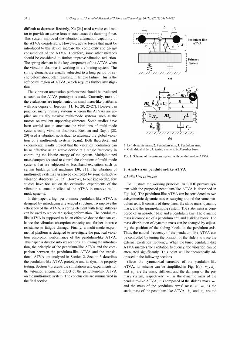
To illustrate the working principle, an SODF primary sys-
tem with the proposed pendulum-like ATVA is described in
Fig. 1(a). The pendulum-like ATVA can be considered as two
axisymmetric dynamic masses swaying around the same pen-
dulum axis. It consists of three parts: the static mass, dynamic
mass, and the spring-damping system. The static mass is com-
posed of an absorber base and a pendulum axis. The dynamic
mass is composed of a pendulum arm and a sliding block. The
mass distribution of dynamic mass can be changed by adjust-
ing the position of the sliding blocks at the pendulum axis.
Thus, the natural frequency of the pendulum-like ATVA can
be controlled by tuning the position of the sliders to trace the
external excitation frequency. When the tuned pendulum-like
ATVA matches the excitation frequency, the vibration can be
attenuated significantly. This point will be theoretically ad-
dressed in the following sections.
Given the symmetrical structure of the pendulum-like
ATVA, its scheme can be simplified in Fig. 1(b). ,p
m ,pk
and pc are the mass, stiffness, and the damping of the pri-
mary system, respectively. am is the dynamic mass of the
pendulum-like ATVA; it is composed of the slider’s mass 1m
and the mass of the pendulum arms’ mass 2.m
sm is the
static mass of the pendulum-like ATVA. ak and
ac are the
(a)
(b)
1. Left dynamic mass; 2. Pendulum axis; 3. Pendulum arm;
4. Cylindrical slider; 5. Spring element; 6. Absorber base.
Fig. 1. Scheme of the primary system with pendulum-like ATVA.

X. Gong et al. / Journal of Mechanical Science and Technology 26 (11) (2012) 3411~3422 3413
stiffness and damping of the spring element, respectively. l
is the distance between the smart spring element and the axis.
R is the distance between the centroid of the slider and the
axis, and R it can be adjusted to track frequency-varying
disturbances. L is the length of the pendulum arm. r is the
radius of the cylindrical slider. f is the exciting force ap-
plied on the primary system. px is the displacement of the
primary system. a
θ is the angular displacement of the pendu-
lum-like ATVA. According to Newton's law [34], the equa-
tions of motion can be expressed as follows:
2 2 2
1 1 2 1 2
2 2
1 2 1 2
1 1[ ] [ ]
3 2
0
1[ ( )] ( )
2
p
a a
p d p
p p p p
m r m R m L m R m L x
c l k l
m m m m x m R m L
c x k x f
θ
θ θ
θ
+ + + +
+ + = + + + + ++ + =
&& &&
&
&&&&
&
. (1)
Defining ,p p p
k mω = (2 ),p p p pc mξ ω= ,
a a ak mω =
and (2 ),a a a ac mξ ω= where
pω and
pξ are the natural
frequency and the damping ratio of the primary system, re-
spectively, and a
ω and aξ are the relative natural frequency
and the damping ratio of the pendulum-like ATVA, respec-
tively. It should be noted Note that a
ω is not equal to the
natural frequency of the pendulum-like ATVA. In fact, it is
the natural frequency of the translational ATVA whose spring
element is the same as that of the pendulum-like ATVA. In
this paper, a
ω it is defined as the relative natural frequency.
From Eq. (1), the driving point mobility of the primary system
with a pendulum-like ATVA attached can be obtained as fol-
lows:
1
2 2 2
1
( )( )
( )
1
[ (1 ) ( ) 2 1]1 2
p
p p p p p p
XH
F
Lm j
R
ωω
ω
µ ϕω µ η ρ ξ
µ
= =
− + Ω − + Ω + Ω ++
%
%
(2)
where
2 2
2 2 2 2
1( )
21
( ) 2 13
a
a a a
R LR
r R L j
η ϕρ
η η ϕ ξ
+ Ω=− + + Ω + Ω +
% % %
% %%
. (3)
In Eqs. (2) and (3), the non-dimensional parameters are de-
fined as follows:
1 2
1, , ,
, , , ,
s a s
a p a a
p a
p a
m m m m m
m m m m
r L Rr L R
l l l
µ µ η ϕ
ω ωω ω
+= = = =
= = = Ω = Ω =
% %%
. (4)
When the pendulum-like ATVA is removed, the driving
point mobility of the primary system can be written as fol-
lows:
0 2 2
1( )
[ 2 1]p p p p p
Hm j
ωω ξ
=−Ω + Ω +
. (5)
Here, the vibration attenuation effect is defined as the ratio
of the driving point mobility of the primary system with and
without the pendulum-like ATVA attached. Based on the
work of Deng [20] and Xu [24], ratio ,γ which reflects the
effect of vibration absorption capacity, can be defined as
1
0
2
2 2
1
20lg | |
2 120lg | | .
(1 ) ( ) 2 11 2
p p p
p p p p
H
H
j
Lj
R
γ
ξ
µ ϕµ η ρ ξ
µ
= =
−Ω + Ω +
− + Ω − + Ω + Ω ++
%
%
(6)
When the pendulum-like ATVA is working, the natural fre-
quency will be turned to trace the external excitation fre-
quency in real time. Hence,
nω ω= (7)
where n
ω is the natural frequency of the pendulum-like ATVA,
which can be obtained by setting px to zero in Eq. (1).
2
2 2 21
3
a
n
r R L
ωω
η η ϕ=
+ +% %%
(8)
Substituting Eq. (8) into Eq. (7), the control strategy of the
pendulum-like ATVA can be rewritten as follows:
2
2
2
1
3a
LR r
ϕη η
= − −Ω
%% % . (9)
If the pendulum-like ATVA is not controlled and the posi-
tion of the sliders is fixed (the natural frequency of the pendu-
lum-like ATVA is kept at a fixed value), it can be regarded as
a pendulum-like TVA. Usually, the natural frequency of the
ATVA is fixed at the natural frequency of the primary system.
n pω ω= (10)
Similarly, substituting Eq. (10) into Eq. (7), the position of
the sliders can be calculated by
2 2
2
3
ap LR r
ϕη η
Ω= − −
%% % (11)
where ap a p
ω ωΩ = .
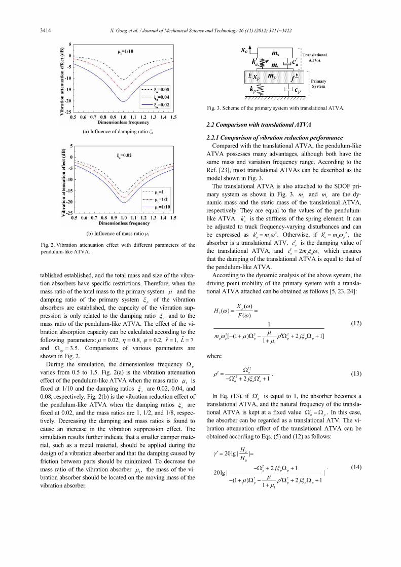
Generally, various parameters of the primary system are es-
3414 X. Gong et al. / Journal of Mechanical Science and Technology 26 (11) (2012) 3411~3422
tablished established, and the total mass and size of the vibra-
tion absorbers have specific restrictions. Therefore, when the
mass ratio of the total mass to the primary system µ and the
damping ratio of the primary system p
ξ of the vibration
absorbers are established, the capacity of the vibration sup-
pression is only related to the damping ratio aξ and to the
mass ratio of the pendulum-like ATVA. The effect of the vi-
bration absorption capacity can be calculated according to the
following parameters: 0.02,µ = 0.8,η = 0.2,ϕ = 1,r =% 7L =%
and 3.5.ap
Ω = Comparisons of various parameters are
shown in Fig. 2.
During the simulation, the dimensionless frequency p
Ω
varies from 0.5 to 1.5. Fig. 2(a) is the vibration attenuation
effect of the pendulum-like ATVA when the mass ratio 1µ is
fixed at 1/10 and the damping ratios aξ are 0.02, 0.04, and
0.08, respectively. Fig. 2(b) is the vibration reduction effect of
the pendulum-like ATVA when the damping ratios aξ are
fixed at 0.02, and the mass ratios are 1, 1/2, and 1/8, respec-
tively. Decreasing the damping and mass ratios is found to
cause an increase in the vibration suppression effect. The
simulation results further indicate that a smaller damper mate-
rial, such as a metal material, should be applied during the
design of a vibration absorber and that the damping caused by
friction between parts should be minimized. To decrease the
mass ratio of the vibration absorber 1,µ the mass of the vi-
bration absorber should be located on the moving mass of the
vibration absorber.
2.2 Comparison with translational ATVA
2.2.1 Comparison of vibration reduction performance
Compared with the translational ATVA, the pendulum-like
ATVA possesses many advantages, although both have the
same mass and variation frequency range. According to the
Ref. [23], most translational ATVAs can be described as the
model shown in Fig. 3.
The translational ATVA is also attached to the SDOF pri-
mary system as shown in Fig. 3. am and
sm are the dy-
namic mass and the static mass of the translational ATVA,
respectively. They are equal to the values of the pendulum-
like ATVA. ak′ is the stiffness of the spring element. It can
be adjusted to track frequency-varying disturbances and can
be expressed as 2.a ak m ω′ = Otherwise, if 2 ,
a a pk m ω′ = the
absorber is a translational ATV. ac′ is the damping value of
the translational ATVA, and 2 ,a a ac m ξ ω′ = which ensures
that the damping of the translational ATVA is equal to that of
the pendulum-like ATVA.
According to the dynamic analysis of the above system, the
driving point mobility of the primary system with a transla-
tional ATVA attached can be obtained as follows [5, 23, 24]:
2
2 2 2
1
( )( )
( )
1
[ (1 ) 2 1]1
p
p p p p p p
XH
F
m j
ωω
ω
µω µ ρ ξ
µ
= =
′− + Ω − Ω + Ω ++
(12)
where
2
2 2 1
a
a a aj
ρξ′Ω
′ =′ ′−Ω + Ω +
. (13)
In Eq. (13), if a′Ω is equal to 1, the absorber becomes a
translational ATVA, and the natural frequency of the transla-
tional ATVA is kept at a fixed value a p′Ω = Ω . In this case,
the absorber can be regarded as a translational ATV. The vi-
bration attenuation effect of the translational ATVA can be
obtained according to Eqs. (5) and (12) as follows:
2
0
2
2 2
1
20lg | |
2 120lg | |
(1 ) 2 11
p p p
p p p p
H
H
j
j
γ
ξµ
µ ρ ξµ
′ = =
−Ω + Ω +
′− + Ω − Ω + Ω ++
. (14)
(a) Influence of damping ratio ξa
(b) Influence of mass ratio µ1
Fig. 2. Vibration attenuation effect with different parameters of the
pendulum-like ATVA.
Fig. 3. Scheme of the primary system with translational ATVA.
X. Gong et al. / Journal of Mechanical Science and Technology 26 (11) (2012) 3411~3422 3415
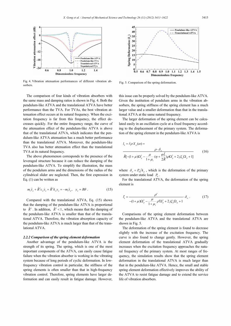
The comparison of four kinds of vibration absorbers with
the same mass and damping ratios is shown in Fig. 4. Both the
pendulum-like ATVA and the translational ATVA have better
performance than the TVA. For TVAs, the best vibration at-
tenuation effect occurs at its natural frequency. When the exci-
tation frequency is far from this frequency, the effect de-
creases quickly. For the entire frequency range, the curve of
the attenuation effect of the pendulum-like ATVA is above
that of the translational ATVA, which indicates that the pen-
dulum-like ATVA attenuation has a much better performance
than the translational ATVA. Moreover, the pendulum-like
TVA also has better attenuation effect than the translational
TVA at its natural frequency.
The above phenomenon corresponds to the presence of the
leveraged structure because it can reduce the damping of the
pendulum-like ATVA. To simplify the illustration, the mass
of the pendulum arms and the dimensions of the radius of the
cylindrical slider are neglected. Then, the first expression in
Eq. (1) can be written as
2 2
1 1, .
a a a a a p am y R c y R k y m x y Rθ+ + = − =% %&& & && (15)
Compared with the translational ATVA, Eq. (15) shows
that the damping of the pendulum-like ATVA is proportional
to 2R% . In addition, 2 1R <% , which means that the damping of
the pendulum-like ATVA is smaller than that of the transla-
tional ATVA. Therefore, the vibration absorption capacity of
the pendulum-like ATVA is much larger than that of the trans-
lational ATVA.
2.2.2 Comparison of the spring element deformation
Another advantage of the pendulum-like ATVA is the
strength of its spring. The spring, which is one of the most
important components of the ATVA, can easily cause fatigue
failure when the vibration absorber is working in the vibrating
system because of long periods of cyclic deformation. In low-
frequency vibration control in particular, the stiffness of the
spring elements is often smaller than that in high-frequency
vibration control. Therefore, spring elements have larger de-
formation and can easily result in fatigue damage. However,
this issue can be properly solved by the pendulum-like ATVA.
Given the institution of pendulum arms in the vibration ab-
sorbers, the spring stiffness of the spring element has a much
larger value and a smaller deformation than that in the transla-
tional ATVA at the same natural frequency.
The larger deformation of the spring element can be calcu-
lated easily in an oscillation cycle at a fixed frequency accord-
ing to the displacement of the primary system. The deforma-
tion of the spring element in the pendulum-like ATVA is
2 2
1
( )
[ (1 ) ( ) 2 1]1 2
k p
st
p p p p
l r X
LR j
R
ρ ω
ρ δµ ϕ
µ η ρ ξµ
= =
⋅
− + Ω − + Ω + Ω ++
%
%%
%
(16)
where 0st pP kδ = , which is the deformation of the primary
system under static load 0P .
For the translational ATVA, the deformation of the spring
element is
2 2
1
(1 ) 2 11
k st
p p p p
l
j
ρδ
µµ ρ ξ
µ
′′ = ⋅
′− + Ω − Ω + Ω ++
. (17)
Comparisons of the spring element deformation between
the pendulum-like ATVA and the translational ATVA are
shown in Fig. 5.
The deformation of the spring element is found to decrease
slightly with the increase of the excitation frequency. The
curve is also found to change gently. However, the spring
element deformation of the translational ATVA gradually
increases when the excitation frequency approaches the natu-
ral frequency of the primary system. At most ranges of fre-
quency, the simulation results show that the spring element
deformation in the translational ATVA is much larger than
that in the pendulum-like ATVA. Hence, the small and stable
spring element deformation effectively improves the ability of
the ATVA to resist fatigue damage and to extend the service
life of vibration absorbers.
Fig. 4. Vibration attenuation performances of different vibration ab-
sorbers.
Fig. 5. Comparison of the spring deformation.

3416 X. Gong et al. / Journal of Mechanical Science and Technology 26 (11) (2012) 3411~3422
3. The design and dynamic property of the pendu-
lum-like ATVA
3.1 The prototype of the pendulum-like ATVA
According to the previous analysis, the pendulum-like ATVA
performs better than the translational ATVA in terms of vibra-
tion reduction and fatigue damage resistance. These results indi-
cate that the pendulum-like ATVA is more suitable for engi-
neering applications. In this paper, a mechanical pendulum-like
ATVA is designed and can be considered as two axisymmetric
dynamic masses swaying around the same pendulum axis.
The model of the pendulum-like ATVA is shown in Fig. 6.
As shown in Fig. 6, the pendulum-like ATVA is composed
of pendulum arms, pendulum axis, base, cylindrical sliders,
and a bow spring blade. The cylindrical slider consists of a
stepping motor and its installation seats. The cylindrical slider
and the pendulum arms are jointed with the rack and pinion to
ensure accuracy in transmission. By using a stepping motor,
the slider can move freely along the pendulum arm, and the
natural frequency of the pendulum-like ATVA can be
changed to trace the external excitation frequency. The step-
ping motor must function as a self-locking stepping motor to
ensure that the pendulum-like ATVA works as a TVA when
the control system fails. The cylindrical sliders and the pendu-
lum arms constitute the dynamic mass of the pendulum-like
ATVA. The stepping motor, which acts as a part of the dy-
namic mass, can make best use of the space and raise the utili-
zation of mass. The bow spring blade should be chosen for its
good holding capacity and large lateral rigidity. It should also
meet the requirements of long-term cycle deformation use
with stability and low cost.
3.2 Dynamic characteristics of the prototype
A vibration table is used to study the dynamic properties of
the pendulum-like ATVA. The schematic of the testing sys-
tem is shown in Fig. 7.
The pendulum-like ATVA is fixed on a vibration table. The
signal analyzer provides a sweep sinusoidal excitation signal
to drive the system via a power amplifier. Two accelerometers
(model: CA-YD, manufactured by Sinocera Piezotronics Inc.,
China) are placed on the pendulum arm, and one accelerome-
ter is placed on the vibration table to record their responses.
The acceleration signals of the vibration table and the pendu-
lum arm are then sent to the dynamic signal analyzer (Signal-
Calc430, Data Physics Corporation, USA) with the input sig-
nals and the output signal of the prototype. With these signals,
the transmissibility relating the output signal to the input sig-
nal can be obtained using fast Fourier transform (FFT) analy-
sis in the dynamic signal analyzer. The peak of the transmissi-
bility curve is the natural frequency of the prototype. With the
transmissibility curve, the damping ratio can be computed
using the half power bandwidth method.
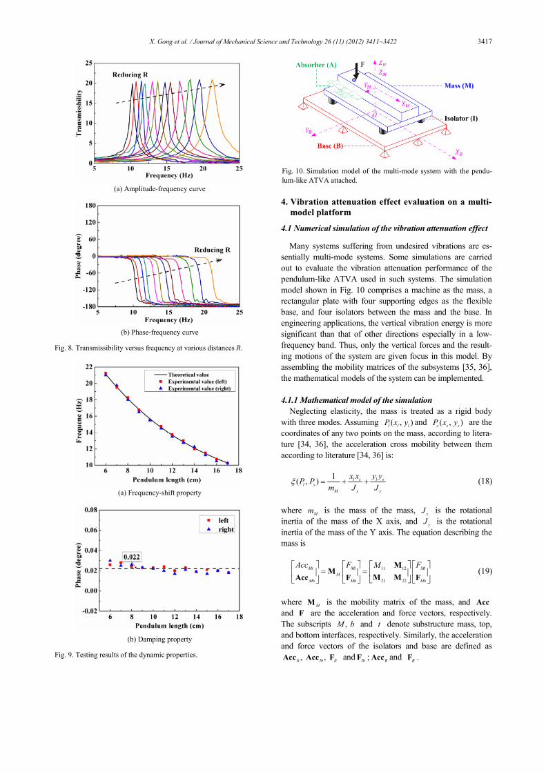
Fig. 8 shows the amplitude-frequency curves and the phase-
frequency curves of the transmissibility of the left pendulum
arm. The results indicate that transmissibility curves move
rightward by reducing the distance R between the centroid of
the slider and the axis, which means that the natural frequency
of the pendulum-like ATVA varies with distance R.
By reading the peak values of the transmissibility in Fig. 8,
the obtained frequency-shift property of the left pendulum arm
is shown in Fig. 9(a).
As described in this figure, the natural frequency of the left
pendulum arm changes from 10.25 Hz to 21.25 Hz when the
distance R varies from 17 cm to 6 cm. Therefore, the pendu-
lum-like ATVA prototype has the capability to change its
frequency by 207%. Using the same method, the frequency-
shift property of the right pendulum arm can also be obtained.
The natural frequency of the right pendulum arm varies from
10.25 Hz to 21 Hz, which is much closer to the right pendu-
lum arm. Moreover, the experiment values are well agreed
with the theoretical values. The damping ratios obtained by
using the half power bandwidth method are shown in Fig. 9(b).
The average damping ratio is roughly 0.022, indicating that
tthe which demonstrates that the damping of the pendulum-
like prototype is low.
(a) Pendulum-like ATVA
(b) Slide
Fig. 6. Scheme of pendulum-like ATVA.
1. Pendulum-like ATVA; 2.Vibration table; 3. Accelerometer
4. Charge amplifiers; 5. Dynamic signal analyzer; 6. Computer.
Fig. 7. Schematic of the test system for the measurement of the dy-
namic properties of the prototype.
X. Gong et al. / Journal of Mechanical Science and Technology 26 (11) (2012) 3411~3422 3417
4. Vibration attenuation effect evaluation on a multi-
model platform
4.1 Numerical simulation of the vibration attenuation effect
Many systems suffering from undesired vibrations are es-
sentially multi-mode systems. Some simulations are carried
out to evaluate the vibration attenuation performance of the
pendulum-like ATVA used in such systems. The simulation
model shown in Fig. 10 comprises a machine as the mass, a
rectangular plate with four supporting edges as the flexible
base, and four isolators between the mass and the base. In
engineering applications, the vertical vibration energy is more
significant than that of other directions especially in a low-
frequency band. Thus, only the vertical forces and the result-
ing motions of the system are given focus in this model. By
assembling the mobility matrices of the subsystems [35, 36],
the mathematical models of the system can be implemented.
4.1.1 Mathematical model of the simulation
Neglecting elasticity, the mass is treated as a rigid body
with three modes. Assuming ( , )l l lP x y and ( , )
s s sP x y are the
coordinates of any two points on the mass, according to litera-
ture [34, 36], the acceleration cross mobility between them
according to literature [34, 36] is:
1( , ) l s l s
l s
M x y
x x y yP P
m J Jξ = + + (18)
where Mm is the mass of the mass,
xJ is the rotational
inertia of the mass of the X axis, and yJ is the rotational
inertia of the mass of the Y axis. The equation describing the
mass is
11 12
21 22
Mt Mt Mt
M
Mb Mb Mb
Acc F FM = =
MM
M MAcc F F (19)
where M
M is the mobility matrix of the mass, and Acc
and F are the acceleration and force vectors, respectively.
The subscripts ,M b and t denote substructure mass, top,
and bottom interfaces, respectively. Similarly, the acceleration
and force vectors of the isolators and base are defined as
,It
Acc ,Ib
AccIt
F andIb
F ;B
Acc and B
F .
(a) Amplitude-frequency curve
(b) Phase-frequency curve
Fig. 8. Transmissibility versus frequency at various distances R.
(a) Frequency-shift property
(b) Damping property
Fig. 9. Testing results of the dynamic properties.
Fig. 10. Simulation model of the multi-mode system with the pendu-
lum-like ATVA attached.
3418 X. Gong et al. / Journal of Mechanical Science and Technology 26 (11) (2012) 3411~3422
The sub-matrices of M
M are
11[ ( , )]
F FM P Pξ=
12 1 4[ ( , )]
F lP Pξ ×=M
21 12
T=M M 22 4 4
[ ( , )]l sP Pξ ×=M ( , 1,2,3,4)l s =
with FP and
lP representing the position coordinates of the
exciting force and the four isolators.
The mass attached to the pendulum-like ATVA will affect
its mobility matrix. Setting ,px
pk and
pc to zero in Eq.
(1), we can obtain the acceleration admittance at the setting
point of the pendulum-like ATVA.
1
[1 ( ) ]2
A
A
A
a
AccM
F Lm
R
ϕη ρ
= =
+ +%
%
(20)
The A
Acc and AF are the acceleration and force vectors
at the setting point of the pendulum-like ATVA, respectively.
In considering the force applied on the pendulum-like ATVA,
the equation describing the mass with the pendulum-like
ATVA attached is altered as:
Mt Mt
M AM
Mb Mb
Ma AA
A A
Acc F
MAcc F
=
M MAcc F
M (21)
where
1 2 3 4[ ( , ) ( , ) ( , ) ( , ) ( , )]T
Am a F a a a aP P P P P P P P P Pξ ξ ξ ξ ξ=M ,
,TmA AM=M M
[ ( , )]AA a a
M P Pξ= ( , , )a A B C= .
With aP representing the position coordinate with the set-
ting point of the pendulum-like ATVA, the pendulum-like
ATVA can be mounted in there are three locations (A, B, C)
to choose from to mount on the pendulum-like ATVA. By
combining Eqs. (20) and (21), A
Acc and AF can be elimi-
nated from Eq. (21). The modified equation is:
ˆ
[ ( ) ]
Mt Mt
M
Mb Mb
Mt
M Am A AA mA
Mb
Acc F
FM M
=
= + −
MAcc F
M M MF
. (22)
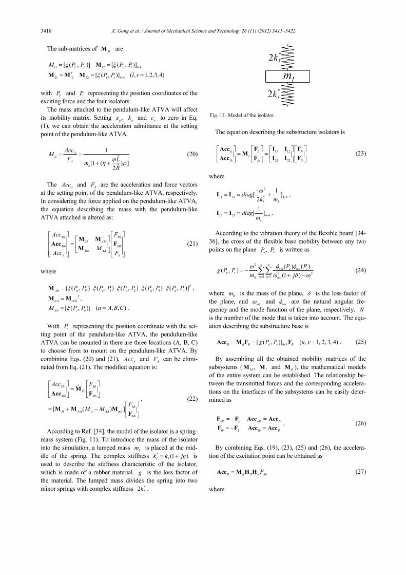
According to Ref. [34], the model of the isolator is a spring-
mass system (Fig. 11). To introduce the mass of the isolator
into the simulation, a lumped mass Im is placed at the mid-
dle of the spring. The complex stiffness * (1 )I Ik k jg= + is
used to describe the stiffness characteristic of the isolator,
which is made of a rubber material. g is the loss factor of
the material. The lumped mass divides the spring into two
minor springs with complex stiffness *2Ik .
The equation describing the substructure isolators is
11 12
21 22
It It It
I
Ib Ib Ib
= =
Acc F FI IM
Acc F FI I (23)
where
2
11 22 4 4*
1[ ]2
I I
diagk m
ω×
−= = +I I ,
12 21 4 4
1[ ]
I
diagm
×= =I I .
According to the vibration theory of the flexible board [34-
36], the cross of the flexible base mobility between any two
points on the plane ,uP
vP is written as
2
2 21 1
( ) ( )( , )
(1 )
N N
mn u mn v
u v
m nB mn
P PP P
m j
ω φ φχ
ω δ ω= =
= −+ −∑∑ (24)
where Bm is the mass of the plane, δ is the loss factor of
the plane, and mn
ω and mnφ are the natural angular fre-
quency and the mode function of the plane, respectively. N
is the number of the mode that is taken into account. The equ-
ation describing the substructure base is
4 4[ ( , )]
B B B u v BP Pχ ×= =Acc M F F ( , 1, 2, 3, 4)u v = . (25)
By assembling all the obtained mobility matrices of the
subsystems ( ,M
M I
M and B
M ), the mathematical models
of the entire system can be established. The relationship be-
tween the transmitted forces and the corresponding accelera-
tions on the interfaces of the subsystems can be easily deter-
mined as
Mb It Mb It
Ib B Ib B
= − =
= − =
F F Acc Acc
F F Acc Acc. (26)
By combining Eqs. (19), (23), (25) and (26), the accelera-
tion of the excitation point can be obtained as
B B B A MtF=Acc M H H (27)
where
Fig. 11. Model of the isolator.

X. Gong et al. / Journal of Mechanical Science and Technology 26 (11) (2012) 3411~3422 3419
1
22 11 12 21
1
22 21
( )
( )
A B
B B
−
−
= + −
= +
H M I I H M
H M I I.
With Eqs. (22) and (27), the response of the system with the
pendulum-like ATVA attached can be computed by replacing
the sub-matrices of M
M with that of ˆM
M . When the pendu-
lum-like ATVA is attached to the multi-mode system, the
dynamic characteristics of the system will be changed. In this
workstudy, the attenuation of the average vibration of the
flexible base is used to represent the vibration attenuation
effect of the pendulum-like ATVA. The vibration attenuation
effect of the pendulum-like ATVA is stated as follows:
20lg b with
b without
Acc
Accγ −
−
= (28)
where b with
Acc − and b without
Acc − are the average acceleration
responses of the flexible base with and without the DVA at-
tached, respectively. They can be calculated by the following
formula as
4
1
4
Bi
i
b
Acc
Acc ==∑
(29)
where Bi
Acc is the vibration acceleration amplitude of the
number i test point on the flexible base. The smaller the γ is,
the better the effect that can be achieved.
4.1.2 Simulation results
In the simulation, the concerned frequency band ranged
from 10 Hz to 20 Hz. Corresponding to subsequent experi-
ments, the following data are used in the calculations:
j t
MtF e ω= ( 0.35, 0)
FP = −
300Mm Kg= 225
YJ Kg m= ⋅ 25.2
XJ Kg m= ⋅
0.5Im Kg= 0.14g = 744193 /
Ik N m=
1092Bm Kg= 0.05δ = ( 0.22, 0.3)
lP = ± ±
4.5am Kg= 1r =% 612500 /
ak N m=
0.022aξ = 7L =% ( 0.8, 0.2)ϕ η= =
( 0.35, 0.25)AP = − ( 0.35, 0)
BP = − ( 0.35, 0.25)
CP = − −
If only the vertical vibration is considered, the system will
have three vibration modes: vertical vibration mode, rotation
mode around the X-axis, and rotation mode around the Y-axis.
The undamped natural frequencies of three modes can be de-
termined as follows:
1 4 1 4 74419316
2 2 300
I
vertical
m
kf Hz
mπ π×
= = ≈ ,
2 241 1 4 744193 0.224
2 2 5.2
I i y
X axis
x
k Cf Hz
Jπ π−
−
× ×= = ≈ ,
2 21 4 1 4 744193 0.22
122 2 25
I i x
Y axis
y
k Cf Hz
Jπ π−
−
× ×= = ≈ .
The excitation force is applied along the X-axis, which is
the nodal line of the rotation mode around the X-axis; there-
fore, this mode cannot be excited.
Fig. 12 shows the simulation results. When the excitation
frequency is close to 16 Hz, the vertical vibration mode con-
tributes considerably to the vibration. The pendulum-like
ATVA fixed at any position can exert positive effects on at-
tenuating the vibration because this mode has no nodal line.
Bordered by the Y-axis, the pendulum-like ATVA located on
the same side of the excitation is found to work better. The
farther the installation location is away from the nodal line, the
better the effect that can be obtained.
The vibration with the frequency closest to 12 Hz depends
primarily on the rotation mode of the Y-axis. Therefore, the
vibration can be attenuated by the pendulum-like ATVA ex-
cept when a nodal line of this mode (Y-axis) is installed. The
situation is similar when the frequency is close to 16 Hz.
However, the effect is more obvious when the pendulum-like
ATVA is placed on the same side of the excitation.
If the excitation frequency lies between 12 and 16 Hz, the
pendulum-like ATVA on the same side of the excitation force
will have evident vibration attenuation effect. However, the
pendulum-like ATVA on the opposite side receives a negative
result, indicating that the vibration of the system is increased
by the pendulum-like ATVA. The simulation results indicate
that the ATVA should be installed on the same side of the
excitation.
4.2 Evaluation experiments of the vibration attenuation ef-
fect
To evaluate the vibration attenuation effect of the prototype
of the pendulum-like ATVA, a massive multi-mode platform
is designed in accordance with the theoretical model in Fig. 10.
Fig. 13 shows the photograph of the experimental platform. A
rigid mass supported by four rubber isolators is fixed on the
Fig. 12. Simulation results of the vibration attenuation effect.

3420 X. Gong et al. / Journal of Mechanical Science and Technology 26 (11) (2012) 3411~3422
elastic base welded by steel plates. The natural frequencies of
the elastic base are much larger than that of the mass. There-
fore, the vibration of the system is mainly affected by the
modes of the mass in the low frequency. The major parame-
ters of the platform, such as mass, rotation inertia, and stiff-
ness of the isolator are similar to that used in simulation. The
pendulum-like ATVA is placed on one side of the mass. The
eccentric excitation is applied by an electromagnetic exciter.
An impedance head connecting the mass and the exciter is
used to monitor the acceleration and force signals. Four accel-
erometers are placed near the isolators to measure the vibra-
tion of the flexible base. As the mass of the platform is 300 kg.
the ratio of the mass of the platform and the mass of the pen-
dulum-like ATVA is 60:1.
With these signals measured by the impedance head, the
admittance relating the acceleration to the force signal is ob-
tained through FFT analysis. The admittance spectrum of the
system without an absorber attached is shown in Fig. 14. Here,
two peaks corresponding to the rotation mode and the vertical
vibration mode are found in the curve.
In this experiment, the system is excited by a series of sin-
gle frequencies to approximate a swept sine excitation. The
amplitude of the excitation force is 80 N, and the frequency
range is 10 Hz to 20 Hz. The pendulum-like ATVA is con-
trolled by a control box composed of a step motor driver (SH-
20403, Beijing Hollysys Inc., China) and a self-made proces-
sor with a core of DSP-TMS320F2812 (Texas instrument
Company, USA). Before the control process is started, the
initial frequency of the pendulum-like ATVA, the relational
table between the natural frequency, and the position of the
sliding blocks at the pendulum axis are set. When the pendu-
lum-like ATVA is working, the signals of vibration of the
experimental platform are sampled by the control system. The
sampling time interval and the sampling numbers are 0.001 s
and 1024, respectively. Through the sampled signal, we can
obtain the dominant frequency of the excitation force by FFT.
A look-up table is then used to compute the desired position
and to drive the motor further to tune the slider to the desired
position at the pendulum axis. In this way, the control system
can adjust the frequency of the pendulum-like ATVA to trace
the external excitation frequency as rapidly as possible. Ac-
cording to Eq. (28), the vibration attenuation effect is charac-
terized by comparing the average vibration of the flexible base
with and without an absorber (TVA and ATVA).
Fig. 15 shows the experimental results of the vibration at-
tenuation effect. The ratio of the platform and the absorber
mass is about 60, and the pendulum-like ATVA is fixed on
location A (the same side with the excitation), as shown in Fig.
10. If the natural frequency is fixed at 16 Hz, the uncontrolled
pendulum-like ATVA can be regarded as a pendulum-like
TVA. For the pendulum-like TVA, the best vibration attenua-
tion effect occurs at its natural frequency. The effect goes
down when the excitation frequency is far from this frequency.
At some frequencies, the values of the effects are even larger
than 0, indicating that the vibration of the system is increased
by the pendulum-like TVA. For the ATVA whose natural
frequency is tuned to trace the excitation frequency, its vibra-
tion attenuation effect is better than that of the TVA within the
entire adjustable frequency band except at 16 Hz. The curve
has two troughs at the natural frequencies of the system (12
and 16 Hz), which means that the pendulum-like ATVA
works much better in attenuating large vibrations. The best
effect of the pendulum-like ATVA reaches roughly 8.5 dB at
12 Hz. The numerical results of the vibration attenuation ef-
fect are computed with the method presented in Section 4. A
1. Pendulum-like ATVA; 2. Control box; 3. Flexible base;
4. Isolator; 5. Mass; 6. Impedance head; 7. Accelerometer;
8. Excitation; 9. Power amplifier; 10. Dynamic signal analyzer;
11. Charge amplifiers; 12. Computer.
Fig. 13. Photograph of the experimental set-up.
Fig. 14. Admittance of the evaluation platform.
Fig. 15. Experimental results of the vibration attenuation effect.

X. Gong et al. / Journal of Mechanical Science and Technology 26 (11) (2012) 3411~3422 3421
comparison between the simulation results and experimental
data is conducted. Fig. 15 shows that the experimental data
and numerical curve are very close. The average error be-
tween the experimental data and the simulation results is
smaller than 0.52 dB for the pendulum-like ATVA, and the
value of this index is smaller than 0.48 dB for the pendulum-
like ATVA. The main error lies in the setting of the boundary
conditions and in the usage of simplified theoretical models.
The results indicate that the dynamic model is reasonable and
that the experimental data are reliable.
5. Conclusions
In this work, a novel pendulum-like ATVA that consists of
two axisymmetric pendulum arms swaying around the same
pendulum axis is developed. The natural frequency of this
ATVA can be tuned from 10.25 Hz to 21 Hz by adjusting the
distance R between the centroid of the slider and the pendu-
lum axis, which varies from 17 cm to 6 cm. The damping of
the prototype is rather small, and the average damping ratio is
0.022. Compared with translational ATVA, the pendulum-like
ATVA decreases the damping of the ATVA as well as the
deformation of the spring. Hence, the vibration absorption
capacity is enhanced, and resistance to fatigue damage ability
is increased.
To investigate the vibration adsorption performance, simu-
lations are carried out using the transmission mobility method
to predict the vibration characteristics of the multi-mode sys-
tem with the pendulum-like ATVA attached theoretically. The
pendulum-like ATVA fixed on location A is found to be ca-
pable of controlling all the modes of the system and to receive
a good effect within a frequency range. The simulation results
are verified through experimental studies conducted on a
multi-mode platform comprising a mass, isolator, and a flexi-
ble base. The experimental results demonstrate that the pendu-
lum-like ATVA mounted on location A can reduce the vibra-
tion effectively in a broad frequency range. The best effect
reaches 8.5 dB when the ratio of the mass of the platform and
the mass of the pendulum-like ATVA is roughly 60:1. The
experimental results agree well with the theoretical calculation.
Therefore, this kind of pendulum-like ATVA has great poten-
tial in engineering applications.
Acknowledgment
Financial support from the National Natural Science Foun-
dation of China (Grant No. 11125210) and the Funds of the
Chinese Academy of Sciences for Key Topics in Innovation
Engineering (Grant No. KJCX2-EW-L02) are gratefully ac-
knowledged.
References
[1] H. Frahm, Device for damping vibrations of bodies, U.S.
Patent: 989958 (1909).
[2] J. T. Chung, Vibration absorber for reduction of the in-plane
vibration in an optical disk drive, Ieee Transactions on Con-
sumer Electronics, 50 (2) (2004) 552-557.
[3] T. X. Wu, On the railway track dynamics with rail vibration
absorber for noise reduction, Journal of Sound and Vibration,
309 (3-5) (2008) 739-755.
[4] A. C. Webster and R. Vaicaitis, Application of tuned mass
dampers to control vibrations of composite floor systems,
Engineering Journal-American Institute of Steel Construc-
tion Inc, 29 (3) (1992) 116-124.
[5] H. Mori, O. Mikhyeyev, T. Nagamine, M. Mori and Y. Sato,
Effect of a dynamic absorber on friction-induced vibration of
a rectangular plate, Journal of Mechanical Science and
Technology, 24 (1) (2010) 93-96.
[6] L. D. Viet and Y. Park, Vibration control of the axisymmet-
ric spherical pendulum by dynamic vibration absorber mov-
ing in radial direction, Journal of Mechanical Science and
Technology, 25 (7) (2011) 1703-1709.
[7] D. J. Inman, Engineering Vibration, Prentice–Hall, Engle-
wood Cliffs, USA (1994).
[8] M. J. Brennan, Actuators for active vibration control - Tun-
able resonant devices, Applied Mechanics and Engineering,
5 (1) (1999) 63-74.
[9] J. Q. Sun, M. R. Jolly and M. A. Norris, Passive, adaptive
and active tuned vibration absorbers - a survey, Journal of
Mechanical Design, 117 (1995) 234-242.
[10] A. H. von Flotow, Adaptive tuned vibration absorbers:
tuning laws, tracking agility, sizing and physical implemen-
tation, Proceedings of Noise-Con, 94 (1994) 81-101.
[11] N. Jalili and B. Fallahi, Design and dynamic analysis of an
adjustable inertia absorber for semiactive structural vibration
attenuation, Journal of Engineering Mechanics-Asce, 128
(12) (2002) 1342-1348.
[12] M. A. Franchek, M. W. Ryan and R. J. Bernhard, Adaptive
passive vibration control, Journal of Sound and Vibration,
189 (5) (1996) 565-585.
[13] K. Nagaya, A. Kurusu, S. Ikai and Y. Shitani, Vibration
control of a structure by using a tunable absorber and an op-
timal vibration absorber under auto-tuning control, Journal
of Sound and Vibration, 228 (4) (1999) 773-792.
[14] J. P. Carneal, F. Charette and C. R. Fuller, Minimization of
sound radiation from plates using adaptive tuned vibration
absorbers, Journal of Sound and Vibration, 270 (4-5) (2004)
781-792.
[15] P. L. Walsh and J. S. Lamancusa, A variable stiffness vi-
bration absorber for minimization of transient vibrations,
Journal of Sound and Vibration, 158 (2) (1992) 195-211.
[16] M. R. F. Kidner and M. J. Brennan, Varying the stiffness of
a beam-like neutralizer under fuzzy logic control, Journal of
Vibration and Acoustics-Transactions of the ASME, 124 (1)
(2002) 90-99.
[17] P. Bonello, M. J. Brennan and S. J. Elliott, Vibration con-
trol using an adaptive tuned vibration absorber with a vari-
able curvature stiffness element, Smart Materials & Struc-
tures, 14 (5) (2005) 1055-1065.

3422 X. Gong et al. / Journal of Mechanical Science and Technology 26 (11) (2012) 3411~3422
[18] J. Liu and K. F. Liu, A tunable electromagnetic vibration
absorber: Characterization and application, Journal of Sound
and Vibration, 295 (3-5) (2006) 708-724.
[19] E. Rustighi, M. J. Brennan and B. R. Mace, A shape memory
alloy adaptive tuned vibration absorber: design and implemen-
tation, Smart Materials & Structures, 14 (1) (2005) 19-28.
[20] H. X. Deng, X. L. Gong and L. H. Wang, Development of
an adaptive tuned vibration absorber with magnetorheologi-
cal elastomer, Smart Materials & Structures, 15 (5) (2006)
N111-N116.
[21] X. Z. Zhang and W. H. Li, Adaptive tuned dynamic vibra-
tion absorbers working with MR elastomers, Smart Struc-
tures and Systems, 5 (5) (2009) 517-529.
[22] M. J. Brennan, Vibration control using a tunable vibration
neutralizer, Proceedings of the Institution of Mechanical En-
gineers Part C, Journal of Mechanical Engineering Science,
211 (2) (1997) 91-108.
[23] H. L. Sun, P. Q. Zhang, X. L. Gong and H. B. Chen, A
novel kind of active resonator absorber and the simulation on
its control effort, Journal of Sound and Vibration, 300 (1-2)
(2007) 117-125.
[24] Z. B. Xu, X. L. Gong, G. J. Liao and X. M. Chen, An ac-
tive-damping-compensated magnetorheological elastomer
adaptive tuned vibration absorber, Journal of Intelligent Ma-
terial Systems and Structures, 21 (10) (2010) 1039-1047.
[25] K. F. Liu, L. Liao and J. Liu, Comparison of two auto-
tuning methods for a variable stiffness vibration absorber,
Transactions of the Canadian Society for Mechanical Engi-
neering, 29 (1) (2005) 81-96.
[26] M. Kidner and M. J. Brennan, Improving the performance
of a vibration neutraliser by actively removing damping,
Journal of Sound and Vibration, 221 (4) (1999) 587-606.
[27] N. Olgac and C. Huang, On the stability of a tuned vibra-
tion absorber for time varying multiple frequencies, Journal
of Vibration and Control, 8 (4) (2002) 451-465.
[28] J. Dayou and M. J. Brennan, Optimum tuning of a vibration
neutralizer for global vibration control, Proceedings of the
Institution of Mechanical Engineers Part C-Journal of Me-
chanical Engineering Science, 215 (C8) (2001) 933-942.
[29] J. Dayou and M. J. Brennan, Experimental verification of
the optimal tuning of a tunable vibration neutralizer for
global vibration control, Applied Acoustics, 64 (3) (2003)
311-323.
[30] R. S. Jangid and T. K. Datta, Performance of Multiple
Tuned Mass dampers for torsionally coupled system, Earth-
quake Engineering & Structural Dynamics, 26 (3) (1997)
307-317.
[31] W. J. Hsueh, Vibration transmissibility of a unidirectional
multi degree of freedom system with multiple dynamic ab-
sorbers, Journal of Sound and Vibration, 229 (4) (2000)
793-805.
[32] L. Zuo and S. A. Nayfeh, Minimax optimization of multi-
degree-of-freedom tuned-mass dampers, Journal of Sound
and Vibration, 272 (3-5) (2004) 893-908.
[33] S. A. Vera, M. Febbo, C. G. Mendez and R. Paz, Vibrations
of a plate with an attached two degree of freedom system,
Journal of Sound and Vibration, 285 (1-2) (2005) 457-466.
[34] S. S. Rao, Mechanical vibrations, fourth edition, Pearson
Prentice Hall, Upper Saddle River, NJ, USA (2004).
[35] Y. P. Xiong, J. T. Xing and W. G. Price, Power flow analy-
sis of complex coupled systems by progressive approaches,
Journal of Sound and Vibration, 239 (2) (2001) 275-295.
[36] H. L. Sun, K. Zhang, P. Q. Zhang and H. B. Chen, Applica-
tion of dynamic vibration absorbers in floating raft system,
Applied Acoustics, 71 (3) (2010) 250-257.
Xinglong Gong received his doctorate
degree in both experimental mechanics
and optical measurement mechanics
from the University of Science and
Technology of China and the Saitama
University in 1996, respectively. He is
currently a professor in the University of
Science and Technology of China. His
current interests include intelligent material, vibration control,
and mechanical design.
Chao Peng received his bachelor degree
in mechanics engineering from Hefei
University of Technology in 2004. He is
currently a Ph.D student at the Univer-
sity of Science and Technology of China.
His main research interests are vibration
control and mechanical design.