a performance and scalability evaluation of the ns-3
TRANSCRIPT

U.S. Army Research, Development and Engineering Command
Ken Renard, Charles Peri, Jerry Clarke
A Performance and Scalability Evaluation
of the NS-3 Distributed Scheduler
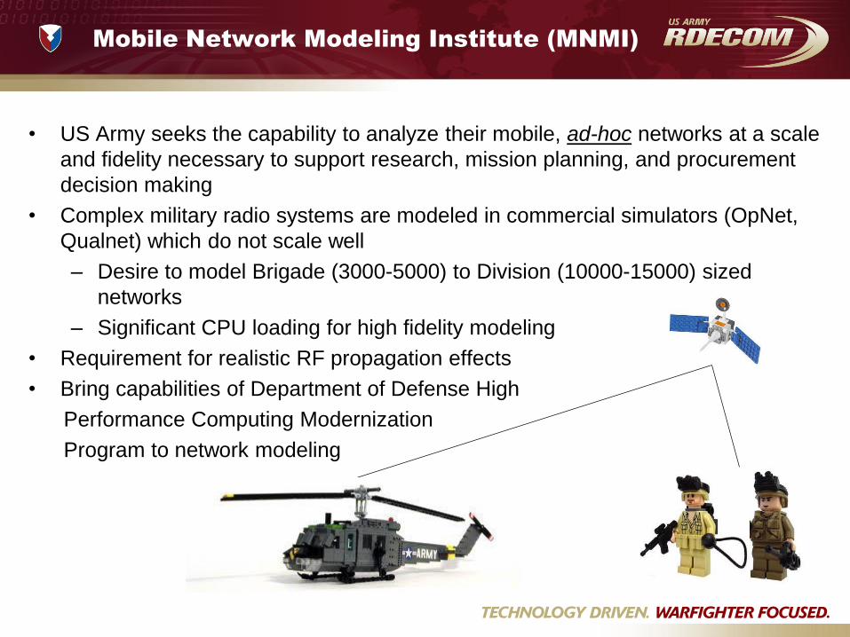
Mobile Network Modeling Institute (MNMI)
• US Army seeks the capability to analyze their mobile, ad-hoc networks at a scale
and fidelity necessary to support research, mission planning, and procurement
decision making
• Complex military radio systems are modeled in commercial simulators (OpNet,
Qualnet) which do not scale well
– Desire to model Brigade (3000-5000) to Division (10000-15000) sized
networks
– Significant CPU loading for high fidelity modeling
• Requirement for realistic RF propagation effects
• Bring capabilities of Department of Defense High
Performance Computing Modernization
Program to network modeling

DoD High Performance Computing
Modernization Program

NS-3 Performance on
HPC Platforms
– Goal is to determine how NS-3 performs and scales on HPC platforms and
what factors influence performance and scalability
– Build a partially realistic, partially performance-driven scenario and run on various
core counts
– NS-3 Distributed Scheduler available as of version 3.8 (May 2010)
– Implements conservative Parallel Discrete Event Simulator (PDES)
– Special Point-To-Point links connect network across Logical Processes (LPs) – LP-to-LP communications via the Message Passing Interface (MPI)
– Larger look-ahead times improve performance – Each LP can compute a series of events independently up until a synchronization point in time
Point-to-Point
MPI

NS3 Distributed Scheduler1
• PTP links can be inserted somewhat transparently into scenario
• Minimize inter-federate communication
• MPI (Message Passing Interface) used to negotiate minimum time step in future where each federate will not send message to another federate – MPI_AllGather() – all ranks publish
their value, and wait to receive values from all other ranks
• Maximize “Look-ahead” value based on inter-federate link latency – Gives larger time slices of independent
computation
• Careful decomposition of network topology into federates is currently manual and static throughout simulation
MPI_AllGather ()
MPI_AllGather ()
Tim
e
Federate
Gra
nt
Tim
e 0
G
ran
t Ti
me
1
1Pelkey, Joshua, Riley, George, 2011. Distributed Simulation with MPI in ns-3. Workshop in ns-3, Barcelona, Spain.

Hardware Platforms
“Harold”
• SGI Altix ICE 8200
• 1344 8-core compute nodes
(2.8GHz Intel Xeon X5560) – 10752 total compute cores
• 24G memory per node
• 4X DDR Infiniband interconnect
• Max. theoretical: 109.3 Teraflops
“MJM”
• Linux Networx Advanced Technology
Cluster
• 1100 quad-core compute nodes
(3.0GHz each) – 4400 total compute cores
• 8G memory per node
• 4x DDR Infiniband interconnect
• Max. theoretical: 52.8 Teraflops
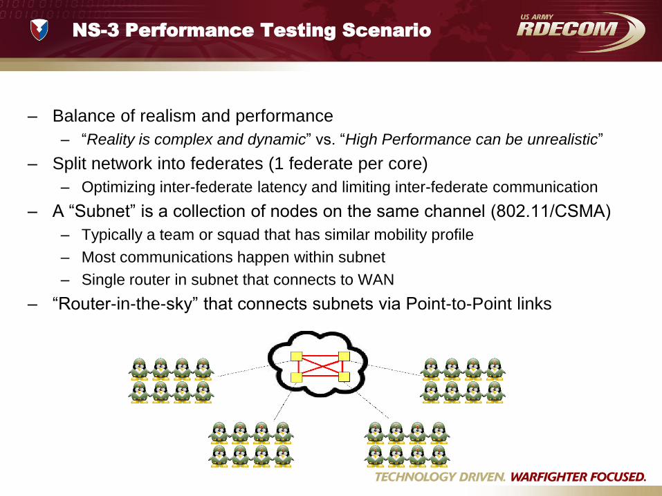
NS-3 Performance Testing Scenario
– Balance of realism and performance
– “Reality is complex and dynamic” vs. “High Performance can be unrealistic”
– Split network into federates (1 federate per core)
– Optimizing inter-federate latency and limiting inter-federate communication
– A “Subnet” is a collection of nodes on the same channel (802.11/CSMA)
– Typically a team or squad that has similar mobility profile
– Most communications happen within subnet
– Single router in subnet that connects to WAN
– “Router-in-the-sky” that connects subnets via Point-to-Point links

NS-3 Performance Testing
Traffic and Mobility Profiles
• Ad-hoc 802.11 networks use OLSR routing
– Significant processing and traffic overhead
• Situational Awareness (SA) reported by
each node to subnet router
– Subnet router collects SA, then multicasts
report to other subnets
– 10s period for end node unicast to subnet
router
– 60s period for subnet router multicast to
other subnet routers
• Each subnet has ‘sand-box’ to move
around (100m x 100m)
– Friis propagation for 802.11
– Larger areas yield more loss, less OLSR
OLSR SA
ARP
802.11
Subnet Traffic Distribution 100m x 100m
75%
11%
12%

NS-3 Federate Topology
• Each NS-3 Federate only instantiates its own
subnets, a “mesh” node, and stubs for external
mesh nodes
• Number of PTP links: N2 N
• Requires interface re-numbering
• Static routing for unicast & multicast
• Inter-federate latency maximized
• Time from uplink and downlink latencies
and moved into satellite switching latency
• Intra-federate latency between subnets
matches inter-federate latency
• Scenario run for 20 minutes of simulated time
Mesh Node Mesh Node Mesh Node
Uplink Downlink
Mesh Node
Mesh Node
TM TM
Ti
S S S S S S
TLA
Ti = TLA + TM + TM
time
time
Tup Tdown Tswitch
Tup Tdown Tswitch = TLookahead
Network path latencies from ground station up to satellite,
through satellite switch, and back down to ground station

NS-3 Performance Results
– OLSR dominates scenario (N2)
– Significant processing vs. look-ahead
– Static routing shows lower run times
– OLSR is representative of complex ad-
hoc routing protocols
– Wifi processing scales similarly, but is
insignificant compared to OLSR

Simulator Performance with OLSR
– Packet event rate (per wall-clock time) shows linear scaling versus
number of cores
– Promising results assuming that wireless networks can be broken into
independent federates
– Each federate has enough work to do per grant time (compute time
dominates versus MPI)

Simulator Performance without OLSR
• Drop-off observed in scaling of CSMA/static routing
– Each federate has minimal work to do per grant time
– Workload not enough to offset increasing time for federate synchronization
[MPI_AllGather()]
• Expect to see this for large enough core counts with larger workloads (OLSR)
• CSMA with OLSR showed this behavior at slightly higher core counts

NS-3 Scaling Scenario
• Goal to enable scaling of MANET simulations on the order of 105 nodes while
maintaining high fidelity protocol, traffic, and propagation models.
• Simple scaling tests with NS-3 were conducted to understand effects of
distributed scheduler and MPI interconnect latencies.
– Simple Point-to-Point and CSMA “campus” networks
Campus
Department Department
Net Net Net Net … …
…
…
Campus
Department Department
Net Net Net Net … …
…
…
• UDP packet transfer within and among campuses (campus = federate) • Only 40% of hosts were communicating during simulation
• 1% of those were communicating across federate boundaries • IPv6 with static routing

NS-3 Scaling Results
• Achieved best results limiting each compute node to a single federate
– Each compute node has 8 cores and 18G of usable memory
• Largest run:
– Each federate used 1 core and 17.5G on a compute node
– 176 federates (176 compute nodes)
– 360,448,000 simulated nodes
– 413,704.52 packet receive events per second [wall-clock]

NS-3 Performance and Scaling Optimizations
– Only create nodes that exist in the federate
– Exception is that nodes on remote end of distributed PTP link
– Interface renumbering may be necessary
– Static routing saves significant time over GlobalRouteManager or Nix
vector routing when possible
– IPv6 addressing useful when scaling
– Ability to “move” latency within simulated network
F2
F3
F4 F5
F0
F1
Inter-Federate “Mesh”
F2
F3
F4 F5
F0
F1
Inter-Federate “Mesh” Federate 1 perspective
Packets from F1 go to 1st
interface on remote Federates
Create (N-1) links instead of N*(N-1)/2

Future Work with NS3 and Distributed
Scheduler
• Combination of Distributed and Real-Time schedulers
– Conduct similar performance and scaling tests
• Direct configuration of remote point-to-point link
parameters
– NodeId and interface
– Such that “ghost” nodes are not necessary
• Automating and optimizing federation of network on to
computing platform
– Graph partitioning with METIS
– Partitioning of network before and during simulation run

Future Work with NS3 and Distributed
Scheduler
• Coupling of simulation components via Distributed Shared
Memory
– Allows independent decompositions of problem
• Mobility / Forces Modeling: decompose organizationally
• RF Propagation: decompose geographically
• Network Simulation: decompose topologically
Distributed Shared Memory
Position
Simulator
RF Propagation
Communication Network
Simulator
Thin RTI
X, Y, Z RF Path Loss
Time Advance
Request
Time Advance
Grant

NS-3 in Experimentation
• C4ISR-Network Modernization holds annual events to test emerging
tactical network technologies and their suitability for Army deployment
• Live and virtual entities deployed at Ft. Dix, NJ conducting missions
• Live vehicles and dismounted soldiers have access to range facilities
• Infrastructure provided to measure network performance and connectivity
• Brigade-sized exercises • Platoons or squads of live entities
• Virtual assets constructed in OneSAF environment interact with live
assets • Gateways connect [and optionally translate]
operational messaging between live and virtual
entities • Brigade and Battalion TOCs with live C2 systems

Acknowledgements
• DoD High Performance Computing Modernization Program (HPCMP)
• Josh Pelkey, Dr. George Riley
• NS-3 community