a phenomenological approach to integrating gaussian beam...
TRANSCRIPT

Vision, Modeling, and Visualization (2016)M. Hullin, M. Stamminger, and T. Weinkauf (Eds.)
A Phenomenological Approach to Integrating Gaussian BeamProperties and Speckle into a Physically-Based Renderer
S. Bergmann1, M. Mohammadikaji1, S. Irgenfried1, H. Wörn1, J. Beyerer1,2, C. Dachsbacher1
1Karlsruhe Institute of Technology (KIT), Germany2Fraunhofer Institute of Optronics, System Technologies and Image Exploitation IOSB, Karlsruhe, Germany
AbstractCoherent light exhibits properties that cannot be modeled by geometrical optics. Those properties include the limited focusabil-ity of light beams and the formation of speckle patterns when coherent light is scattered or reflected. We use existing physicalmodels for these phenomena to mimic the behavior of Gaussian beams and the statistical properties of speckle patterns withoutperforming a wave-optics simulation. These models have been integrated into a physically-based renderer with the intention ofsynthesizing sensor data for an optical inspection setup which uses a laser light source. This requires only local changes to therenderer and can also be used for real-time rendering.
Categories and Subject Descriptors (according to ACM CCS): I.3.7 [Computer Graphics]: Three-Dimensional Graphics andRealism—Raytracing
1. Introduction
Coherent light exhibits effects caused by diffraction that cannot bedescribed by geometrical optics. We propose a method to rendera subset of diffraction effects in a physically-based renderer (seePharr and Humphreys [PH04]) to reproduce effects observed inscenes containing coherent light. Contrary to the geometrical opticsassumptions, light in general, even with a tightly limited spectrumcannot be focused onto a single point due to diffraction effects. Thisis especially noticeable when using laser light sources in a scene.Another well-known effect of using such light sources is the forma-tion of speckle patterns (see Fig. 1). A speckle pattern is a granularphenomenon that occurs when coherent light is reflected or scat-tered by an optically rough surface; interference occurs betweenthe waves that were scattered by different surface elements andacquired a phase difference. The emerging patterns of lower andhigher intensity are called speckle patterns [Goo75]. These patternsare a characteristic and noticeable feature of reflected or scatteredcoherent light.
Our work is motivated by the need to synthesize sensor data foran automated optical inspection setup. Laser light sources are oftenused in such setups, for example in laser triangulation. Simulatingthe resulting sensor data is potentially very beneficial because of thecomplex interaction between light and material which turns settingup an inspection setup into a tedious trial and error procedure. Ourmotivation is to reduce the set up time by employing a physically-based renderer to simulate the light transport and thus syntheticallygenerate sensor data. The simulated sensor data can then be used toprovide insights and guidance for the set-up process or to optimize
Figure 1: A photograph of a speckle pattern caused by a laser beam.
the set-up automatically. With regard to the application, it is notour intention to calculate a reference-grade solution but to mimicthe mentioned properties of coherent light to a degree that can beused to qualify laser triangulation setups.
In the optical inspection setup we are working with, we use alaser emitter fitted with a lens that fans out the beam in one dimen-sion. The laser illuminates the target object in the form of a curveand this curve is then recorded by an optical sensor. Using the cap-tured images and based on the principle of triangulation [BLF15],a 3D measurement of the illuminated profile can be generated. Oneof the factors contributing to the uncertainty in the measured dataare speckles [DHH94]; ignoring their effect would adversely im-pact the accuracy of results obtained by such a simulation. Our goal
c© 2016 The Author(s)Eurographics Proceedings c© 2016 The Eurographics Association.

S. Bergmann et al. / A Phenomenological Approach to Integrating Gaussian Beams and Speckle into a Physically-Based Renderer
is to include a laser as a light source in a physically-based rendererand reproduce effects of wave optics that have an impact in our sce-nario: the limited focusability of light beams and speckle patterns.
After reviewing related work, we will first introduce the prop-erties of Gaussian beams and how we integrated them into therenderer (sections 3 and 4) and then continue to do the same forspeckle patterns (sections 5 and 6). This is then followed by a pre-sentation of the resulting images and a discussion of the results.
2. Related work
Our paper touches different research topics and we will present thepublications most relevant to our work.
Our motivation is the simulation of an optical measurement pro-cess using computer graphic methods. The synthetization of sensordata has been a research interest for a long time and we wouldlike to highlight some recent publications. Cajal et al. [CSS15]use computer graphic methods to simulate sensor data intendedto help setting up a laser triangulation setup. They use geomet-rical optics and do not simulate effects of wave optics. Moham-madikaji et al. [MBI∗16] use computer graphics as a tool to simu-late a limited sensor resolution for uncertainty analysis in the con-text of laser triangulation. They account for uncertainty throughwave optic effects in a summarizing manner by including such ef-fects in an image-domain uncertainty but not explicitly modelingthem. A recent publication by Retzlaff et al. [RHBD16] discussesusing computer graphic methods to simulate optical sensor data andto generate synthetic sample data.
The integration of wave optics in physically-based renderers hasbeen the subject of some works. Cuypers at al. [CHB∗12] present acomparison of different approaches and propose the handling ofdiffraction and interference effects by introducing a new BSDFrepresentation. Holzschuch and Pacanowski [HP15] present a re-flectance model that provides a better fit to measured materialsby including diffraction effects. Lindsay and Agu [LA06] renderdiffraction effects in real-time using spherical harmonics.
The speckle phenomenon has been studied extensively with dif-ferent goals. While some publications describe ways to reducespeckles (e.g. McKechnie [McK75]) others make use of specklepatterns to deduce information about microscopic surface deforma-tions (e.g. Ennos [Enn75] and Yamaguchi [Yam93]) or use speckleto detect touches to surfaces (Shih et al. [SDH∗14]).
3. Properties of Gaussian beams
Before going into details about the integration of lasers into thephysically-based renderer, we will review some necessary back-ground information about laser beams in this section.
There are many different types of laser emitters, and the beamscreated by these have different properties. We limit ourselves toGaussian beams because they are commonly used to model the be-havior of laser beams. These beams are emitted by lasers workingin the fundamental TEM00 mode [EE10] and are preferred becausethey provide the best focusability.
The properties of a Gaussian beam that we want to simulate are:
z z
z = 0
w0
w(z)
δ
Figure 2: Schematic of a Gaussian Beam, illustrating the beamwaist (where the beam width w(z) is minimal) and the divergenceδ.
• The width of the beam does not change linearly with traveleddistance.
• Due to diffraction, a laser beam (or any other beam) cannot befocused onto a single point.
Next, we will recapitulate the governing equations for Gaussianbeam propagation that are needed to model the intended behaviorof the beams. The information is taken from Eichler and Eichler[EE10], please refer to this source for more detailed information.
A Gaussian beam has the defining property that its transverseintensity profile is a Gaussian. The beam width w is defined as thelateral distance from the beam center to a point where the beamintensity has decayed to 1/e2 of its center intensity. A Gaussianbeam can be characterized solely by its wavelength λ and its beamwaist w0. The beam waist is the width of the beam at the pointwhere the width is minimal (the focus). The beam width is usuallycalculated as a function of the distance z from the beam waist, sow0 = w(0) and
w(z) = w0
√1+
z2
z2R
(1)
with the Rayleigh range zR =w2
0π
λ(Fig. 2). Further away from the
beam waist (z� zR), the width increases linearly with z: w(z) ≈w0
zzR
with a very good approximation. Using this, the divergence
angle δ can be defined as δ = w0zR
= λ
πw0.
For a given optical power P, we can calculate the beam centerintensity with E0(z) = 2P
πw2(z) . This allows us to calculate the irradi-ance at any point on the central axis of the beam. To determine theirradiance at off-axis points, we use the knowledge that the beamis radially symmetrical with a Gaussian profile. This leads to theexpression for the irradiance at a point x in space:
E(x) = E0(z)e−2r2
w2(z) . (2)
The point x = (x,y,z)T is specified with respect to the beam waist,so z is the distance from the beam waist and r2 = x2 + y2.
In summary, completely defining a beam for rendering requires
c© 2016 The Author(s)Eurographics Proceedings c© 2016 The Eurographics Association.
S. Bergmann et al. / A Phenomenological Approach to Integrating Gaussian Beams and Speckle into a Physically-Based Renderer
the wavelength λ, the beam waist w0, the position of the beam waistand the beam direction to be given in addition to the beam’s opticalpower P.
4. Rendering with Gaussian beam emitters
Typical physically-based renderers are based on geometrical opticsand thus we cannot integrate the Gaussian beams directly like otherlight emitters. The usual assumption for an emitter is that the radi-ance of a ray can be determined if the source point and the directionare known and this is not valid in our case.
Regarding the scope of the changes that are needed, we note thatwhen a Gaussian beam hits a surface and is reflected, its definingproperties are generally lost. We do not handle lenses or mirror sur-faces where these properties would be preserved, i.e. we consideronly the first interaction in a coherent light path after the lens thatshapes the beam (e.g. transforms the beam into a fan) in the fol-lowing description. This means that there are two main cases wehave to take care of: Sampling a light source directly from a pointin the scene (next event estimation) and sampling a ray starting atthe light source.
Before describing our approach we note that we cannot assign aradiance value to a path segment without knowing the position ofboth its vertices. This is not a problem in case of direct light sourcesampling as one vertex of the path segment is already known andthe second can by chosen by our implementation before calculatingthe radiance. However, if we sample a point and direction on thelight source, we will need to first determine the next intersectionbefore calculating the radiance.
Next event estimation
In the context of a next event estimation from a reference point rwe do the following:
1. We transfer the reference point r into a point rL in the local lasercoordinate system where the beam is traveling from the originin positive z direction.
2. If we are rendering a laser line, we now take into account thatdifferent types of lenses can be used to convert a laser beam intoa laser fan. Cylinder lenses and Powell lenses are used in mostcases with the main difference being the fact that they distributethe intensity differently along the beam. While cylinder lensesmaintain the Gaussian profile along the line, Powell lenses dis-tribute the intensity more evenly.Our setup uses a cylinder lens and for cylinder lenses, we canjust scale the local x coordinate (assuming the laser fan planehas the normal (0,1,0)T ) according to the projected length ofthe line at the current distance from the emitter:
x′ = xw(z)
tan α
2 · z.
α is the opening angle of the laser line and x′ is the scaled coor-dinate that is used for the following intensity calculation.
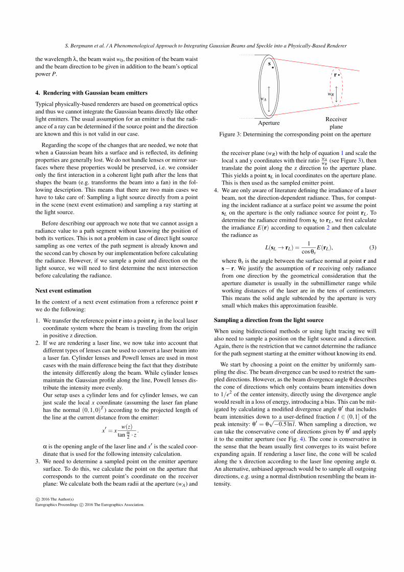
3. We need to determine a sampled point on the emitter aperturesurface. To do this, we calculate the point on the aperture thatcorresponds to the current point’s coordinate on the receiverplane: We calculate both the beam radii at the aperture (wA) and
s
wA
r
wR
ApertureReceiver
planeFigure 3: Determining the corresponding point on the aperture
the receiver plane (wR) with the help of equation 1 and scale thelocal x and y coordinates with their ratio wA
wR(see Figure 3), then
translate the point along the z direction to the aperture plane.This yields a point sL in local coordinates on the aperture plane.This is then used as the sampled emitter point.
4. We are only aware of literature defining the irradiance of a laserbeam, not the direction-dependent radiance. Thus, for comput-ing the incident radiance at a surface point we assume the pointsL on the aperture is the only radiance source for point rL. Todetermine the radiance emitted from sL to rL, we first calculatethe irradiance E(r) according to equation 2 and then calculatethe radiance as
L(sL→ rL) =1
cosθsE(rL), (3)
where θs is the angle between the surface normal at point r ands− r. We justify the assumption of r receiving only radiancefrom one direction by the geometrical consideration that theaperture diameter is usually in the submillimeter range whileworking distances of the laser are in the tens of centimeters.This means the solid angle subtended by the aperture is verysmall which makes this approximation feasible.
Sampling a direction from the light source
When using bidirectional methods or using light tracing we willalso need to sample a position on the light source and a direction.Again, there is the restriction that we cannot determine the radiancefor the path segment starting at the emitter without knowing its end.
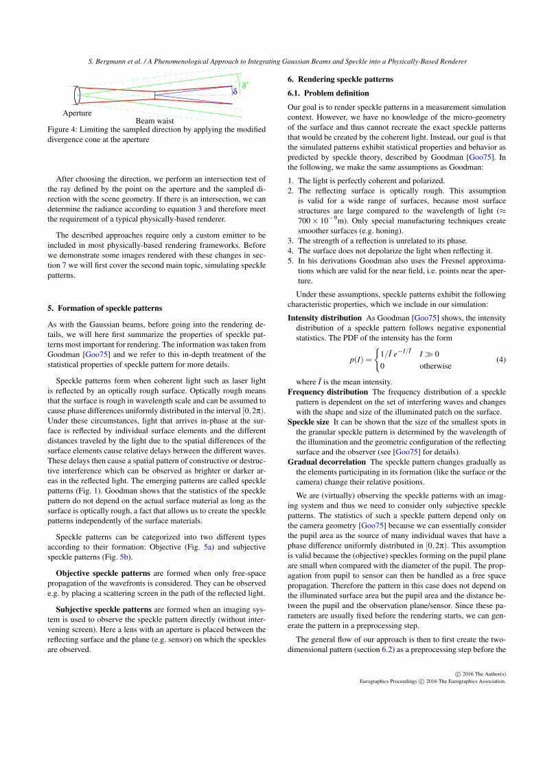
We start by choosing a point on the emitter by uniformly sam-pling the disc. The beam divergence can be used to restrict the sam-pled directions. However, as the beam divergence angle θ describesthe cone of directions which only contains beam intensities downto 1/e2 of the center intensity, directly using the divergence anglewould result in a loss of energy, introducing a bias. This can be mit-igated by calculating a modified divergence angle θ
′ that includesbeam intensities down to a user-defined fraction l ∈ (0,1] of thepeak intensity: θ
′ = θ√−0.5ln l. When sampling a direction, we
can take the conservative cone of directions given by θ′ and apply
it to the emitter aperture (see Fig. 4). The cone is conservative inthe sense that the beam usually first converges to its waist beforeexpanding again. If rendering a laser line, the cone will be scaledalong the x direction according to the laser line opening angle α.An alternative, unbiased approach would be to sample all outgoingdirections, e.g. using a normal distribution resembling the beam in-tensity.
c© 2016 The Author(s)Eurographics Proceedings c© 2016 The Eurographics Association.
S. Bergmann et al. / A Phenomenological Approach to Integrating Gaussian Beams and Speckle into a Physically-Based Renderer
δδ′
Beam waistAperture
Figure 4: Limiting the sampled direction by applying the modifieddivergence cone at the aperture
After choosing the direction, we perform an intersection test ofthe ray defined by the point on the aperture and the sampled di-rection with the scene geometry. If there is an intersection, we candetermine the radiance according to equation 3 and therefore meetthe requirement of a typical physically-based renderer.
The described approaches require only a custom emitter to beincluded in most physically-based rendering frameworks. Beforewe demonstrate some images rendered with these changes in sec-tion 7 we will first cover the second main topic, simulating specklepatterns.
5. Formation of speckle patterns
As with the Gaussian beams, before going into the rendering de-tails, we will here first summarize the properties of speckle pat-terns most important for rendering. The information was taken fromGoodman [Goo75] and we refer to this in-depth treatment of thestatistical properties of speckle pattern for more details.
Speckle patterns form when coherent light such as laser lightis reflected by an optically rough surface. Optically rough meansthat the surface is rough in wavelength scale and can be assumed tocause phase differences uniformly distributed in the interval [0,2π).Under these circumstances, light that arrives in-phase at the sur-face is reflected by individual surface elements and the differentdistances traveled by the light due to the spatial differences of thesurface elements cause relative delays between the different waves.These delays then cause a spatial pattern of constructive or destruc-tive interference which can be observed as brighter or darker ar-eas in the reflected light. The emerging patterns are called specklepatterns (Fig. 1). Goodman shows that the statistics of the specklepattern do not depend on the actual surface material as long as thesurface is optically rough, a fact that allows us to create the specklepatterns independently of the surface materials.
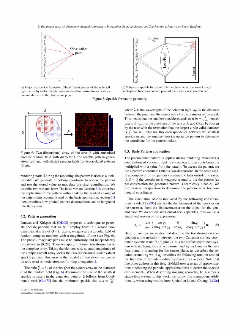
Speckle patterns can be categorized into two different typesaccording to their formation: Objective (Fig. 5a) and subjectivespeckle patterns (Fig. 5b).
Objective speckle patterns are formed when only free-spacepropagation of the wavefronts is considered. They can be observede.g. by placing a scattering screen in the path of the reflected light.
Subjective speckle patterns are formed when an imaging sys-tem is used to observe the speckle pattern directly (without inter-vening screen). Here a lens with an aperture is placed between thereflecting surface and the plane (e.g. sensor) on which the specklesare observed.
6. Rendering speckle patterns
6.1. Problem definition
Our goal is to render speckle patterns in a measurement simulationcontext. However, we have no knowledge of the micro-geometryof the surface and thus cannot recreate the exact speckle patternsthat would be created by the coherent light. Instead, our goal is thatthe simulated patterns exhibit statistical properties and behavior aspredicted by speckle theory, described by Goodman [Goo75]. Inthe following, we make the same assumptions as Goodman:
1. The light is perfectly coherent and polarized.2. The reflecting surface is optically rough. This assumption
is valid for a wide range of surfaces, because most surfacestructures are large compared to the wavelength of light (≈700× 10−9m). Only special manufacturing techniques createsmoother surfaces (e.g. honing).
3. The strength of a reflection is unrelated to its phase.4. The surface does not depolarize the light when reflecting it.5. In his derivations Goodman also uses the Fresnel approxima-
tions which are valid for the near field, i.e. points near the aper-ture.
Under these assumptions, speckle patterns exhibit the followingcharacteristic properties, which we include in our simulation:
Intensity distribution As Goodman [Goo75] shows, the intensitydistribution of a speckle pattern follows negative exponentialstatistics. The PDF of the intensity has the form
p(I) =
{1/I e−I/I I� 00 otherwise
(4)
where I is the mean intensity.Frequency distribution The frequency distribution of a speckle
pattern is dependent on the set of interfering waves and changeswith the shape and size of the illuminated patch on the surface.
Speckle size It can be shown that the size of the smallest spots inthe granular speckle pattern is determined by the wavelength ofthe illumination and the geometric configuration of the reflectingsurface and the observer (see [Goo75] for details).
Gradual decorrelation The speckle pattern changes gradually asthe elements participating in its formation (like the surface or thecamera) change their relative positions.
We are (virtually) observing the speckle patterns with an imag-ing system and thus we need to consider only subjective specklepatterns. The statistics of such a speckle pattern depend only onthe camera geometry [Goo75] because we can essentially considerthe pupil area as the source of many individual waves that have aphase difference uniformly distributed in [0,2π). This assumptionis valid because the (objective) speckles forming on the pupil planeare small when compared with the diameter of the pupil. The prop-agation from pupil to sensor can then be handled as a free spacepropagation. Therefore the pattern in this case does not depend onthe illuminated surface area but the pupil area and the distance be-tween the pupil and the observation plane/sensor. Since these pa-rameters are usually fixed before the rendering starts, we can gen-erate the pattern in a preprocessing step.
The general flow of our approach is then to first create the two-dimensional pattern (section 6.2) as a preprocessing step before the
c© 2016 The Author(s)Eurographics Proceedings c© 2016 The Eurographics Association.
S. Bergmann et al. / A Phenomenological Approach to Integrating Gaussian Beams and Speckle into a Physically-Based Renderer
Observationpoint
z
(a) Objective speckle formation: The different phases of the reflectedlight caused by surface height variations lead to constructive or destruc-tion interference at the observation point.
Emitter
Len
s/Pu
pil
Sens
or
(b) Subjective speckle formation: The de-phased contributions of manypoint-spread functions on each point of the sensor cause interference
Figure 5: Speckle formation geometry.
Q
Q
C
F
Figure 6: Two-dimensional array of the size Q with embeddedcircular random field with diameter C for speckle pattern gener-ation (red) and with shifted random fields for decorrelated patterns(blue).
rendering starts. During the rendering, the pattern is used as a look-up table. We generate a look-up coordinate to access the patternand use the stored value to modulate the pixel contribution. Wedescribe two variants here: The basic variant (section 6.3) describesthe application of the pattern without taking the gradual change ofthe pattern into account. Based on the basic application, section 6.4then describes how gradual pattern decorrelation can be integratedinto the system.
6.2. Pattern generation
Duncan and Kirkpatrick [DK08] proposed a technique to gener-ate speckle patterns that we will employ here: In a zeroed two-dimensional array of Q×Q pixels, we generate a circular field ofrandom complex numbers with a magnitude of one (see Fig. 6).The phase (imaginary part) must be uniformly and independentlydistributed in [0,2π). Then we apply a Fourier transformation tothe complete array. Taking the element-wise squared magnitude ofthe complex result array yields the two-dimensional scalar-valuedspeckle pattern. This array is then scaled so that its entries can bedirectly used as modulators conforming to equation 4.
The ratio QC = hP of the size Q of the square array to the diameter
C of the random field (Fig. 6) determines the size of the smallestspeckle in pixels in the generated pattern. It follows from Good-man’s work [Goo75] that the minimum speckle size is h = λdPI
D
where λ is the wavelength of the coherent light, dPI is the distancebetween the pupil and the sensor and D is the diameter of the pupil.This means that the smallest speckle extends over hI =
hwpixel
sensorpixels if wpixel is the pixel size of the sensor. C and Q can be chosenby the user with the restriction that the largest circle valid diameteris Q
2 . We will later use this correspondence between the smallestspeckle hI and the smallest speckle hP in the pattern to determinethe coordinate for the pattern lookup.
6.3. Basic Pattern application
The precomputed pattern is applied during rendering. Whenever acontribution of coherent light is encountered, that contribution ismultiplied with a value from the pattern. To access the pattern, weuse a pattern coordinate c that is two-dimensional in the basic case.If a component of the pattern coordinate c falls outside the range[0,Q− 1] the coordinate is wrapped around to tile the pattern (asper construction the generated pattern is seamlessly tileable). Weuse bilinear interpolation to determine the pattern value for non-integral coordinates.
The calculation of c is motivated by the following considera-tions: Sjödahl [Sjö95] derives the displacement of the speckles onthe sensor aI from the displacement a on the object for the gen-eral case. We do not consider out-of-focus speckles, thus we use asimplified version of his expression:
aI =−dPI
dSP
(cosq1 0 sinq1
sinq1 sinq2 cosq2 cosq1 sinq2
)a. (5)
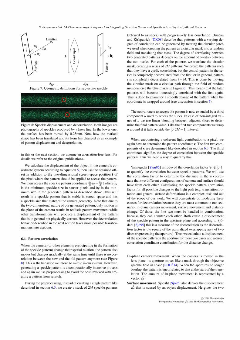
Here, q1 and q2 are angles that describe the transformation (ne-glecting any translation) between the two Cartesian surface coor-dinate systems n and b (Figure 7). n is the surface coordinate sys-tem with n3 being the surface normal and n1,n2 lying on the sur-face plane. b is analog for the sensor plane. q1 describes the ro-tation around n2 while q2 describes the following rotation aroundthe first axis of the intermediate system (Euler angles). Note thatlike other authors in this field, Sjödahl uses a series of approxima-tions (including the paraxial approximations) to derive the speckledisplacements. When describing imaging geometry, he assumes asingle-lens system. In this work, we follow this assumption. Addi-tionally when using results from Sjödahl or Li and Chiang [LC86]
c© 2016 The Author(s)Eurographics Proceedings c© 2016 The Eurographics Association.
S. Bergmann et al. / A Phenomenological Approach to Integrating Gaussian Beams and Speckle into a Physically-Based Renderer
EmitterSu
rfac
e
n3
n2n1
Len
s/Pu
pil
Sens
or
b3
b2b1
D
dSL
dSP dPIFigure 7: Geometric definitions for subjective speckle.
Figure 8: Speckle displacement and decorrelation. Both images arephotographs of speckles produced by a laser line. In the lower one,the surface has been moved by 0.25mm. Note how the markedshape has been translated and its form has changed as an exampleof pattern displacement and decorrelation.
in this or the next section, we assume an aberration-free lens. Fordetails we refer to the original publications.
We calculate the displacement of the object in the camera’s co-ordinate system according to equation 5, then use the obtained off-set in addition to the two-dimensional screen-space position t ofthe pixel where the pattern should be applied to access the pattern.We then access the speckle pattern coordinate hP
h aI +hPhI
t where hIis the minimum speckle size in sensor pixels and hP is the min-imum size in the generated pattern as described above. This willresult in a speckle pattern that is stable in screen space and hasa speckle size that matches the camera geometry. Note that due tothe two-dimensional nature of our generated pattern, only motion inthe plane of the camera results in realistic pattern movement whileother transformations will produce a displacement of the patternthat is in general not physically correct. However, the decorrelationbehavior described in the next section takes more possible transfor-mations into account.
6.4. Pattern correlation
When the camera (or other elements participating in the formationof the speckle pattern) change their spatial relation, the pattern alsomoves but changes gradually at the same time until there is no cor-relation between the new and the old pattern anymore (see Figure8). This is the behavior we intend to mimic in our system. However,generating a speckle pattern is a computationally intensive processand again we use preprocessing to avoid the cost involved with cre-ating a pattern from scratch.
During the preprocessing, instead of creating a single pattern likedescribed in section 6.3, we create a stack of 2M speckle patterns
(referred to as slices) with progressively less correlation. Duncanand Kirkpatrick [DK08] describe that patterns with a varying de-gree of correlation can be generated by treating the circular patchwe used when creating the pattern as a circular mask into a randomfield and translating that mask. The degree of correlating betweentwo generated patterns depends on the amount of overlap betweenthe two masks. For each of the patterns we translate the circularmask, creating a series of 2M patterns. We create the patterns suchthat they have a cyclic correlation, but the central pattern in the se-ries is completely decorrelated from the first, or in general, patterni is completely decorrelated from i+M. This is done be movingthe circular mask on a circular path through the field of randomnumbers (see the blue masks in Figure 6). This means that the laterpatterns will become increasingly correlated with the first again.This is done to guarantee a smooth change of the pattern when thecoordinate is wrapped around (see discussion in section 7).
The coordinate c to access the pattern is now extended by a thirdcomponent u used to access the slices. In case of non-integral val-ues of u we use linear blending between adjacent slices to deter-mine the final pattern value. Like the first two components we wrapu around if it falls outside the [0,2M−1] interval.
When encountering a coherent light contribution to a pixel, weagain have to determine the pattern coordinate c. The first two com-ponents of c are determined like described in section 6.3. The thirdcoordinate signifies the degree of correlation between the specklepatterns, thus we need a way to quantify this.
Yamaguchi [Yam85] introduced the correlation factor γ0 ∈ [0,1]to quantify the correlation between speckle patterns. We will usethe correlation factor to determine the distance in the u coordi-nate that two different configurations of camera and surface shouldhave from each other. Calculating the speckle pattern correlationfactor for all possible changes to the light path (e.g. translation, ro-tation and general surface deformation) is a complex task and outof the scope of our work. We will concentrate on modeling threecauses for decorrelation because they are most common in our sce-nario: in-plane camera movement, surface movement and distancechange. Of those, the first two must be handled in combination,because they can counter each other. Both cause a displacementof the speckle pattern in the aperture plane and according to Sjö-dahl [Sjö95] this is a measure of the decorrelation as the decorrela-tion factor is the square of the normalized overlapping area of twodiscs (representing the aperture). Thus we calculate a displacementof the speckle pattern in the aperture for these two cases and a directcorrelation coordinate contribution for the distance change.
In-plane camera movement When the camera is moved in thelens plane, its aperture moves like a mask through the objectivespeckle field in space [SDH∗14]. When the apertures no longeroverlap, the pattern is uncorrelated to that at the start of the trans-lation. The amount of in-plane movement is represented by avector aC
P .Surface movement Sjödahl [Sjö95] also derives the displacement
aSP that is caused by an object displacement. He gives the two
c© 2016 The Author(s)Eurographics Proceedings c© 2016 The Eurographics Association.
S. Bergmann et al. / A Phenomenological Approach to Integrating Gaussian Beams and Speckle into a Physically-Based Renderer
components of the aperture displacement as
aSP,x =
−dSPcos(q1)
[ax
(12
Sx−1dSL
+12
x −1dSP
)+
ay
(1Sx1Sy
dSL+
1x1y
dSP
)+az
(1Sx1Sz
dSL+
1x1z
dSP
)]+
dSPsin(q1)sin(q2)
cos(q1)cos(q2)
[ax
(1Sx1Sy
dSL+
1x1y
dSP
)+
ay
(12
Sy−1dSL
+12
y −1dSP
)+az
(1Sy1Sz
dSL+
1y1z
dSP
)]and
aSP,y =
−dSPcos(q2)
[ax
(1Sx1Sy
dSL+
1x1y
dSP
)+
ay
(12
Sy−1dSL
+12
y −1dSP
)+az
(1Sy1Sz
dSL+
1y1z
dSP
)].
The symbols 1Sx,1Sy,1Sz and 1x,1y,1y correspond to the com-ponents of the normalized vector from the surface to the laseremitter and of b3, respectively. Both are expressed in terms ofthe coordinate system n1,n2,n3.
Distance change Li and Chiang [LC86] have calculated correla-tion factors for different types of changes to the geometrical con-figuration. For a changing distance between the surface and thecamera (assuming a circular aperture) they give the correlationfactor as
γ0 =
∣∣∣∣ sin( π
2 aO)π
2 aO
∣∣∣∣2 ,
with
aO =1[
2(1+ 1m )F
]2dz
λ
being the out-of-plane pattern displacement of the speckles, dzthe displacement along the optical axis, m the magnificationfactor and F the F-Number of the aperture. It follows that for|dz| = λ[2(1+ 1
m )F ]2 the pattern is decorrelated. This distancewill be referred to as d0
z .
We can now determine the u coordinate by calculating the effec-tive speckle displacement in the aperture plane and combining thiswith the decorrelation caused by the distance change:
u =
(|aC
P +aSP|
D+
dz
d0z
)M.
Using the completed pattern coordinate we access the stack ofspeckle pattern to retrieve the correct interference factor and mod-ulate the coherent light contribution to the pixel.
7. Results and discussion
We integrated our techniques into Mitsuba [Jak10], a research-oriented physically-based renderer, which we then used to generateall the results in this paper. All images have been rendered using256 samples per pixel. Integrating the Gaussian Beam renderingonly required the addition of an emitter plugin in Mitsuba without
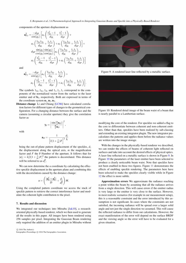
Figure 9: A rendered laser line reflected by a metallic surface.
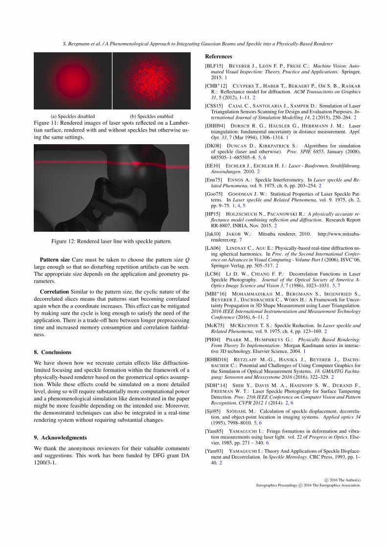
Figure 10: Rendered detail image of the beam waist of a beam thatis nearly parallel to a Lambertian surface.
modifying the core of the renderer. For speckles we added a flag tothe core to differentiate between coherent and non-coherent emit-ters. Other than that, speckles have been realized by sub-classingand extending an existing integrator plugin. The new integrator pre-calculates the patterns and applies them before the radiance valuesare written into the image storage.
With the changes in the physically-based renderer we described,we can render the effects of beams of coherent light reflected onsurfaces and take into account the desired effects of physical optics.A laser line reflected on a metallic surface is shown in Figure 9. InFigure 10 the parameters of the laser emitter have been selected toproduce a clearly noticeable beam waist. Note that speckles havenot been enabled in these two figures. Figure 11 demonstrates theeffects of enabling speckle rendering. The parameters here havebeen selected to make the speckles clearly visible while in Figure12 the effect is more subtle.
Approximation errors We approximate the radiance reachinga point within the beam by assuming that all the radiance arrivesfrom a single direction. This will cause errors if the emitter radiusis very large or the emitter is very close to the surface. However,in most realistic scenarios (for example in our measurement setup),this is a reasonable constraint and the error introduced by this as-sumption is not significant. In cases where the constraints are notsatisfied, the incoming radiance will be spread over a larger solidangle and not just the single direction we assumed. This will causethe reflected radiance to differ from our calculations. However, theexact manifestation of the error will depend on the surface BRDFand the viewing angle so the error will have to be evaluated for agiven situation.
c© 2016 The Author(s)Eurographics Proceedings c© 2016 The Eurographics Association.
S. Bergmann et al. / A Phenomenological Approach to Integrating Gaussian Beams and Speckle into a Physically-Based Renderer
(a) Speckles disabled (b) Speckles enabledFigure 11: Rendered images of laser spots reflected on a Lamber-tian surface, rendered with and without speckles but otherwise us-ing the same settings.
Figure 12: Rendered laser line with speckle pattern.
Pattern size Care must be taken to choose the pattern size Qlarge enough so that no disturbing repetition artifacts can be seen.The appropriate size depends on the application and geometry pa-rameters.
Correlation Similar to the pattern size, the cyclic nature of thedecorrelated slices means that patterns start becoming correlatedagain when the u coordinate increases. This effect can be mitigatedby making sure the cycle is long enough to satisfy the need of theapplication. There is a trade-off here between longer preprocessingtime and increased memory consumption and correlation faithful-ness.
8. Conclusions
We have shown how we recreate certain effects like diffraction-limited focusing and speckle formation within the framework of aphysically-based renderer based on the geometrical optics assump-tion. While these effects could be simulated on a more detailedlevel, doing so will require substantially more computational powerand a phenomenological simulation like demonstrated in the papermight be more feasible depending on the intended use. Moreover,the demonstrated techniques can also be integrated in a real-timerendering system without requiring substantial changes.
9. Acknowledgments
We thank the anonymous reviewers for their valuable commentsand suggestions. This work has been funded by DFG grant DA1200/3-1.
References[BLF15] BEYERER J., LEÓN F. P., FRESE C.: Machine Vision: Auto-
mated Visual Inspection: Theory, Practice and Applications. Springer,2015. 1
[CHB∗12] CUYPERS T., HABER T., BEKAERT P., OH S. B., RASKARR.: Reflectance model for diffraction. ACM Transactions on Graphics31, 5 (2012), 1–11. 2
[CSS15] CAJAL C., SANTOLARIA J., SAMPER D.: Simulation of LaserTriangulation Sensors Scanning for Design and Evaluation Purposes. In-ternational Journal of Simulation Modelling 14, 2 (2015), 250–264. 2
[DHH94] DORSCH R. G., HÄUSLER G., HERRMANN J. M.: Lasertriangulation: fundamental uncertainty in distance measurement. Appl.Opt. 33, 7 (Mar 1994), 1306–1314. 1
[DK08] DUNCAN D., KIRKPATRICK S.: Algorithms for simulationof speckle (laser and otherwise). Proc. SPIE 6855, January (2008),685505–1–685505–8. 5, 6
[EE10] EICHLER J., EICHLER H. J.: Laser - Bauformen, Strahlführung,Anwendungen. 2010. 2
[Enn75] ENNOS A.: Speckle Interferometry. In Laser speckle and Re-lated Phenomena, vol. 9. 1975, ch. 6, pp. 203–254. 2
[Goo75] GOODMAN J. W.: Statistical Properties of Laser Speckle Pat-terns. In Laser speckle and Related Phenomena, vol. 9. 1975, ch. 2,pp. 9–75. 1, 4, 5
[HP15] HOLZSCHUCH N., PACANOWSKI R.: A physically accurate re-flectance model combining reflection and diffraction. Research ReportRR-8807, INRIA, Nov. 2015. 2
[Jak10] JAKOB W.: Mitsuba renderer, 2010. http://www.mitsuba-renderer.org. 7
[LA06] LINDSAY C., AGU E.: Physically-based real-time diffraction us-ing spherical harmonics. In Proc. of the Second International Confer-ence on Advances in Visual Computing - Volume Part I (2006), ISVC’06,Springer-Verlag, pp. 505–517. 2
[LC86] LI D. W., CHIANG F. P.: Decorrelation Functions in LaserSpeckle Photography. Journal of the Optical Society of America A-Optics Image Science and Vision 3, 7 (1986), 1023–1031. 5, 7
[MBI∗16] MOHAMMADIKAJI M., BERGMANN S., IRGENFRIED S.,BEYERER J., DACHSBACHER C., WÖRN H.: A Framework for Uncer-tainty Propagation in 3D Shape Measurement using Laser Triangulation.2016 IEEE International Instrumentation and Measurement TechnologyConference (2016), 6–11. 2
[McK75] MCKECHNIE T. S.: Speckle Reduction. In Laser speckle andRelated Phenomena, vol. 9. 1975, ch. 4, pp. 123–169. 2
[PH04] PHARR M., HUMPHREYS G.: Physically Based Rendering:From Theory To Implementation. Morgan Kaufmann series in interac-tive 3D technology. Elsevier Science, 2004. 1
[RHBD16] RETZLAFF M.-G., HANIKA J., BEYERER J., DACHS-BACHER C.: Potential and Challenges of Using Computer Graphics forthe Simulaton of Optical Measurement Systems. 18. GMA/ITG Fachta-gung: Sensoren und Messsysteme 2016 (2016), 322–329. 2
[SDH∗14] SHIH Y., DAVIS M. A., HASINOFF S. W., DURAND F.,FREEMAN W. T.: Laser Speckle Photography for Surface TamperingDetection. Proc. 25th IEEE Conference on Computer Vision and PatternRecognition, CVPR 2012 1 (2014). 2, 6
[Sjö95] SJÖDAHL M.: Calculation of speckle displacement, decorrela-tion, and object-point location in imaging systems. Applied optics 34(1995), 7998–8010. 5, 6
[Yam85] YAMAGUCHI I.: Fringe formations in deformation and vibra-tion measurements using laser light. vol. 22 of Progress in Optics. Else-vier, 1985, pp. 271 – 340. 6
[Yam93] YAMAGUCHI I.: Theory And Applications of Speckle Displace-ment and Decorrelation. In Speckle Metrology. CRC Press, 1993, pp. 1–40. 2
c© 2016 The Author(s)Eurographics Proceedings c© 2016 The Eurographics Association.