a piecewise continuous timoshenko beam model for the ... · a piecewise continuous timoshenko beam...
TRANSCRIPT
A Piecewise Continuous Timoshenko Beam Model for the Dynamic Analysis of Tapered Beam-like Structures
Ji Yao Shen, Elias G. Abu-Saba and
William M. McGinley, Lonnie Sharpe, Jr,
Center for Aerospace Research School of Engineering
North Carolina A&T State University Greensboro, North Carolina 2741 1
Lawrence W. Taylor, Jr.
Control & Guidance Division Langley Research Center
Hampton, Virginia 23665
Submitted to The Journal of Aerospace Engineering
Aerospace Division, American Society of Civil Engineering
ABSTRACT
Distributed parameter modeling is being seen to offer a viable alternative to finite element approach for modeling large flexible space structures. The introduction of the transfer matrix method into the continuum modeling process provides a very useful tool to facilitate the distributed parameter model applied to some more complex configurations. A uniform Timoshenko beam
t-- model for the estimation of the dynamic properties of beam-like structures has given comparable- =
3 6 PREGEDING PAGE EEAPJK NOT FILMED
https://ntrs.nasa.gov/search.jsp?R=19930010270 2018-07-16T21:09:05+00:00Z
results. But many aeronautical and aerospace structures are of the non-uniform sections or sectional properti_es, such as aircraft wing, satellite antenna.
This paper proposes a piecewise continuous Timoshenko beam mode1 which is used for the dynamic analysis of tapered beam-like structures. A tapered beam is divided into several segments
of uniform beam elements. Instead of arbitrarily assumed shape functions used in finite element
analysis, the closed-form solution of the Timoshenko beam equation has been used. Application
of transfer matrix method relates all the elements as a whole. By corresponding boundary conditions and compatible conditions a characteristic equation for the global tapered beam has been
yielded, from which natural frequencies can be derived. A computer simulation is shown in this
paper, and compared with the results obtained from the finite element analysis. While piecewise
continuous Timoshenko beam model decreases the number of elements significantly, comparable
results to the finite element method are obtained.
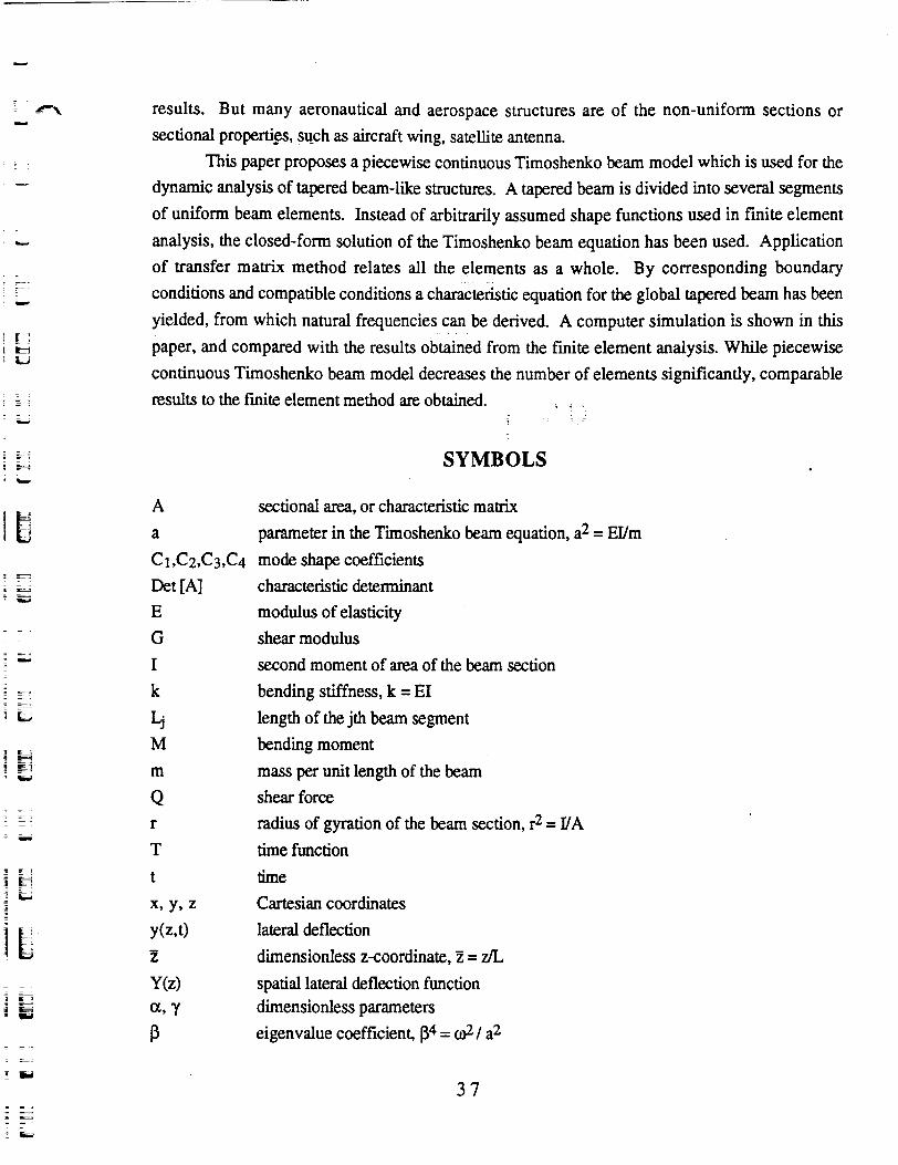
SYMBOLS
sectional area, or characteristic matrix
parameter in the Timoshenko beam equation, a2 = W m
mode shape coefficients
characteristic determinant
modulus of elasticity
shear modulus
second moment of area of the beam section
bending stiffness, k = EI
length of the jth beam segment
bending moment
mass per unit length of the beam
shear force
radius of gyration of the beam section, r2 = UA
time function
t time
X, Y, z Cartesian coordinates
Y(z,~> lateral deflection Z dimensionless z-coordinate, Z = z/L y(z> spatial lateral deflection function a, Y dimensionless parameters P eigenvalue coefficient, P4 = 02 I a2
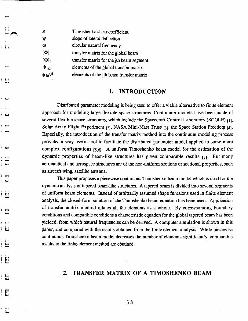
& Tirnoshenko shear coefficient
W slope of lateral deflection o circular natural frequency
[@I transfer matrix for the global beam
[@lj transfer matrix for the jth beam segment
@ k i elements of the global transfer matrix
$ ki(.i) elements of the jth beam transfer matrix
1. INTRODUCTION
- - . . 8 B - g E;; - w
Distributed parameter modeling is being seen to offer a viable alternative to finite element approach for modeling large flexible space structures. Continuum models have been made of several flexible space structures, which include the Spacecraft Control Laboratory (SCOLE) [I],
Solar Array Flight Experiment [21, NASA Mini-Mast Truss 131, the Space Station Freedom [41. Especially, the introduction of the transfer matrix method into the continuum modeling process provides a very useful tool to facilitate the distributed parameter model applied to some more complex configurations [5,61. A uniform Timoshenko beam model for the estimation of the dynamic properties of beam-like structures has given comparable results 171. But many
aeronautical and aerospace structures are of the non-uniform sections or sectional properties, such as aircraft wing, satellite antenna.
This paper proposes a piecewise continuous Timoshenko beam model which is used for the dynamic analysis of tapered beam-like structures. A tapered beam is divided into several segments of uniform beam elements. Instead of arbitrarily assumed shape functions used in finite element analysis, the closed-form solution of the Timoshenko beam equation has been used. Application of transfer matrix method relates @l the elements as a whole. By corresponding boundary conditions and compatible conditions a characteristic equation for the global tapered beam has been yielded, from which natural frequencies can be derived. A computer simulation is shown in this paper, and compared with the results obtained from the finite element analysis. While piecewise continuous Timoshenko beam model decreases the number of elements significantly, comparable results to the frnite element method are obtained.
2. TRANSFER MATRIX OF A TIMOSHENKO BEAM
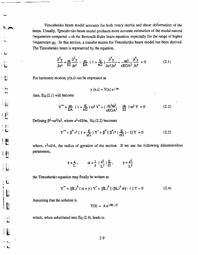
Timoshenko beam model accounts for both rotary inertia and shear deformation of the beam. Usually, Tjmoshpnko beam model produces more accurate estimation of the modal natural fnquencies compared .with the Bernoulli-Euler beam equation, especially for the range of higher frequencies [83. In this section, a transfer matrix for Timoshenko beam model has been derived. The Timoshenko beam is represented by the equation,
For harmonic motion, y(x,t) can be expressed as
y (x,t) = Y(x) e j
then, Eq(2.1) will become
Defining p4=d/a2, where a2=~Um, Eq(2.2) becomes
where, r2=I/A, the radius of gyration of the section. If we use the following dimensionless parameters,
the Timoshenko equation may finally be written as
Assuming that the solution is y@) = Ae(BL)"
which, when substituted into Eq.(2.4), leads to
The solution to the Eq(2.5) is as follows.
Then, the solution to the Eq(2.4) can be expressed as
Y@) = C1 sin (8LZ) + C2 cos (0LZ) + C3 sinh (qLZ) + C4 cosh (qLZ) (2.6)
Similarly, for the bending slope y the differential equation has the same form as the
The solution to Eq.(2.7) will be
Y(z) = olCl cos ( ~ L z ) - alC2 sin ( ~ L z ) + a2C3 cosh (qLZ) + 02C4 sinh (qLZ) (2.8)
where.
For the Timoshenko beam model, the shear force is
or, equivalently,
And the bending moment is -
or, equivalently,
M ( Z ) = ~ Y " + ~ & Y EGA - - -
Eqs. (2.10) and (2.12) can be written in dimensionless format as,
Substituting the solutions of Y(z)(Eq.2.6) and Y(z)(Eq.2.8) into Eqs(2.13) and (2.14), we derive
where, 3 ol = 8 - a ~ 2 p ~ ~ - p p 4 0 1 , 4 a12 = e2- aL2$
4 g l = q3+ a ~ ~ ~ ~ q + y ~ 2 p 4 ~ 2 022 = q2+ aL2P
For the jth beam element, the displacement Y(O), slope Y(O), shear Q(O), and the bending
moment M(0) at the end of z 4 can then be written in matrix form as,
Thus,
where,
Similarly, at the end of z=L, the corresponding quantities are, if written in matrix form,
where,
Substituting Eq.(2.18) into Eq.(2.19) we obtain
where, [@Ij is the transfer matrix of the Timoshenko beam,
and the elements of the transfer matrix [@]j are as follows.
(P21= - - (olq2sine~ - 02012sinhqL) 612+622
9 2 2 = -L (QIQ~ICOSBL + 0201 ~coshqL) oio21+o261 I
0 1 6 2 923 = (- C O S ~ L + C O S ~ ~ L )
k(a l~2l+o2~11) 9 2 4 = -(dlsinO~ + 02sinhqL)
k(012+622)
941 =' kouo22 (COS~L - C O S ~ ~ L ) o12+022
~2 = - --k- (o12qlsineL - o1 1022sinhqL) 01o2 +02o11
g43 = 1 (o2o12sinBL + ~ ~ o ~ ~ s i n h q L ) olql+o2oll
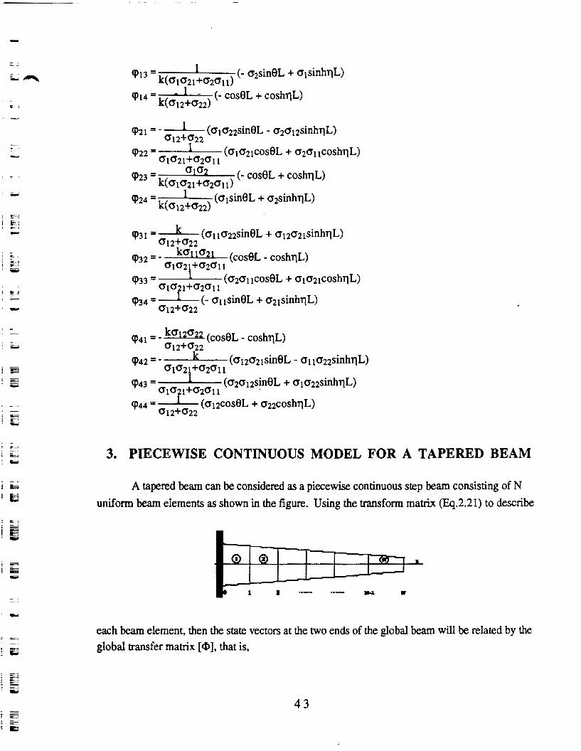
3. PIECEWISE CONTINUOUS MODEL FOR A TAPERED BEAM
A tapered beam can be considered as a piecewise continuous step beam consisting of N uniform beam elements as shown in the figure. Using the transform matrix (Eq.2.21) to describe
each beam element, then the state vectors at the two ends of the global beam will be related by the global transfer matrix [a], that is,

where, the global transfer matrix
Without loss of generality, let us consider the case of N=3. As N=3, the global transfer matrix
willbe
where, the superscripts (j) represent the jth beam, and $ki(i) is the elements of the transfer matrix
for the jth beam.
If we consider a cantilevered beam fmed at the end of z=0, we have the following boundary conditions: at the fixed end: Y(O)=O and y(O)=O; at the free end: Q(L)=O and M(L)=O. Applying
the boundary conditions to the global equation (3.1), we will have
Rearranging the state vector, Eq(3.3) can be written as
-
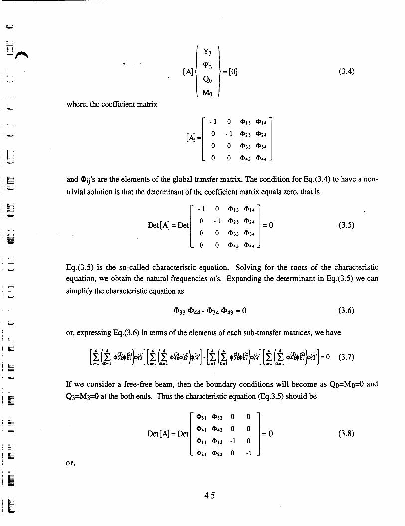
where, the coefficient matrix
and QTij's are the elements of the global transfer matrix. The condition for Eq(3.4) to have a non-
trivial solution is that the determinant of the coefficient matrix equals zero, that is
Eq(3.5) is the so-called characteristic equation. Solving for the roots of the characteristic equation, we obtain the natural frequencies a's. Expanding the determinant in Eq.(3.5) we can
simplify the characteristic equation as
or, expressing Eq(3.6) in terns of the elements of each sub-transfer matrices, we have
If we consider a free-free beam, then the boundary conditions will become as Qo=Mo=O and
Q=M3=O at the both ends. Thus the characteristic equation (Eq.3.5) should be

a 3 1 a 4 2 - a 3 2 a41 = 0 (3.9) - . -
Expressing Eq43.9) in terms of the elements of each sub-transfer matrices, we have
4. COMPUTER SIMULATION
The computer simulation is designed to analyze the natural frequency for a tapered beam with 15-meter length (Fig.4.1). The modulus of elasticity is assumed to be E 2 0 0 * lo9 ~ l r n ~ . To
Pig.4.1 ATapcred Beam
simplify the calculation, the change of the sectional foil is specified by the changes of the second moment of area of the beam section and the mass of the beam segments along the longitudinal axis z, that is, assuming
1 = (0.0222-0.6z+5.375)* (m4) (4.1) and
m = 0.01 1222-0.495z+7.708 (kg.) (4-2)
In so doing, we may readily determine the sectional parameters necessary for the element stiffness and mass matrices when we divide the beam as any desired number of segments. For
example, if we use three uniform beam elements to represent the global tapered beam, then we use z,=2.5, q=7.5 and z3=12.5 to calculate the Ii and mi for each beam element according to Eqs.(4.1)
and (4.2). They are
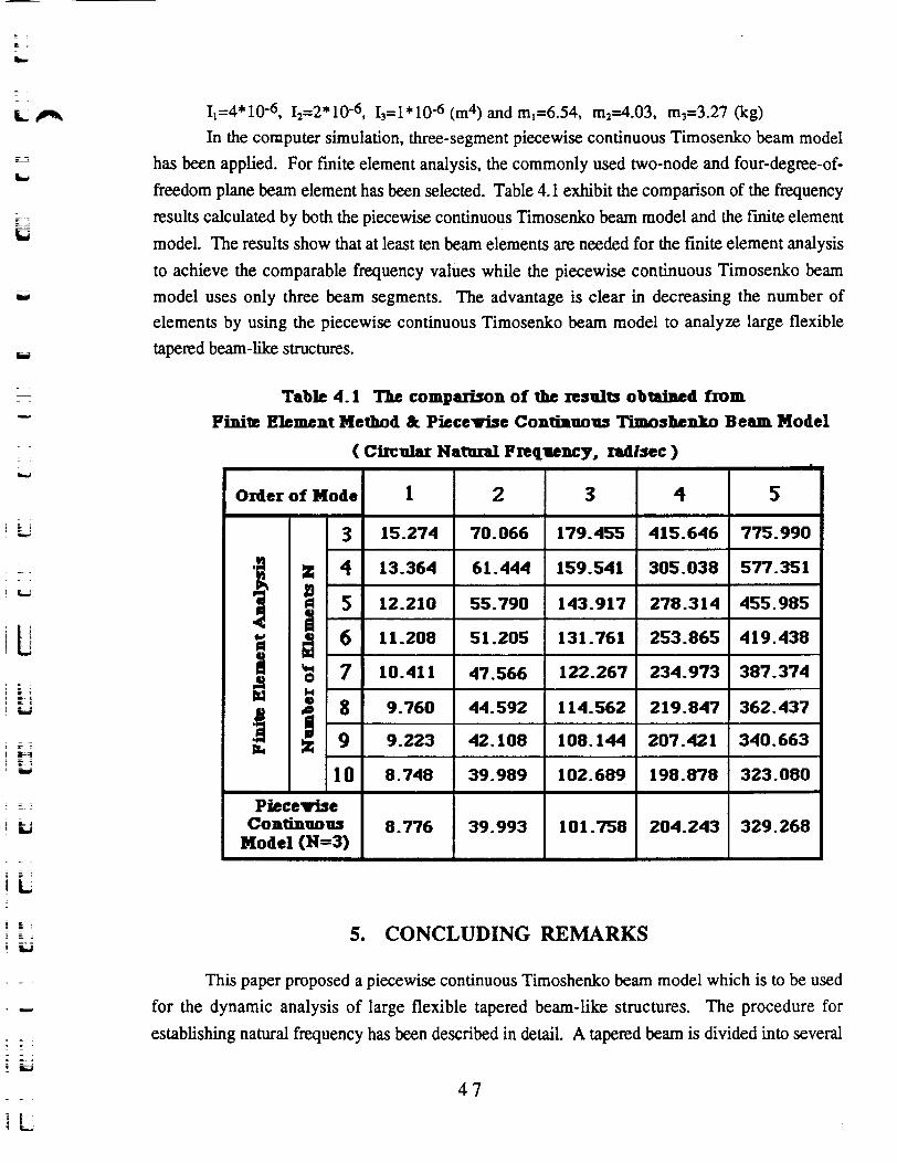
11=4* 12=2* 1 0-6, I,= 1 * 10-6 (m4) and m1=6.54, m2=4.03, m3=3.27 (kg)
In the computer simulation, three-segment piecewise continuous Timosenko beam model has been applied. For finite element analysis, the commonly used two-node and four-degree-of- freedom plane beam element has been selected. Table 4.1 exhibit the comparison of the frequency results calculated by both the piecewise continuous Timosenko beam model and the finite element
model. The results show that at least ten beam elements are needed for the finite element analysis to achieve the comparable frequency values while the piecewise continuous Timosenko beam model uses only three beam segments. The advantage is clear in decreasing the number of elements by using the piecewise continuous Timosenko beam model to analyze large flexible tapered beam-like structures.
Table 4.1 The comparison of the resnlts obtained from Finite Element Method & Piecevise Continwas Timoshenb Beam Model
( Circalar Natnral Fnqaency, xadlsec )
5. CONCLUDING REMARKS
B L1
8
This paper proposed a piecewise continuous Tirnoshenko beam model which is to be used for the dynamic analysis of large flexible tapered beam-like structures. The procedure for establishing natural frequency has been described in detail. A tapered beam is divided into several
W
3 h .
%
Piecevise con^^^
Model (N=3)
6
7
8
9
10
8 - 776
11.208
10.411
9.760
9.223
8.748
39.993
51.205
47.566
44.592
42.108
39.989
10 1,758
131.761
122.267
114.562
108.144
102.689
204.243 329.268
253.865
234.973
219.847
207.421
198.878
419.438
387.374
362.437
340.663
323.080 3
segments of uniform beam elements. Instead of arbitrarily assumed shape functions used in finite element analysis,-the elosed-form solution of the Timoshenko beam equation has been used. Application of transfer matrix method relates all the elements as a whole. By corresponding boundary conditions and compatible conditions a characteristic equation for the global tapered beam has been yielded. Through the root-searching process to the characteristic equation the natural frequencies have been derived. A computer simulation is shown in this paper, and compared with the results obtained from the finite element analysis. While the comparable results is obtained, piecewise continuous Timoshenko beam model decreases the number of elements significantly.
REFERENCE
1. Balakrishnan, A.V.,"A Mathematical Formulation of the SCOLE Problem, Partl", NASA CR 172581, May 1985 2. Taylor, L.W., Jr. and Williams, J.,"Maximum Likelihood Estimation for Distributed Parameter Models of Flexible Spacecraft", IFACIIFORS Symposium on Identification and Parameter Estimation, Beijing , China, 1988
3. Shen, J.Y., Huang, J.K. and Taylor, L.W., Jr.,"Likelihood Estimation for Distributed Parameter Models of Large Beam-like Structures", Journal of Sound and Vibration (1992) 155(3), pp467-480 4. Thomas, S.,"A Continuum Model for Dynamic Analysis of the Space Station", the 40th IAF International Astronautical Congress, Malaga, Spain, Oct.7- 13,1989 5. Shen, J.Y. and Taylor, L.W., Jr.,"Application of Transfer Matrix Method to Estimate the Modal Characteristics of the NASA Mini-Mast Truss", NASA Workshop on Distributed Parameter Modeling and Control of Flexible Aerospace Systems, Williamsburg, VA. June 8- 10,1992
6. Shen, J.Y. and Sharpe, Lonnie,"Applying Transfer Matrix Method to Formulate a Distributed Parameter Model for the LACE Satellite Model", accepted as NASA Contractor Report, 1992 7. Shen, J.Y., Huang, J.K. and Taylor, L.W., Jr.,"Damping Models for Distributed Parameter Estimation of Large Beam-like Structures", the Pacific-Rim International Conference on Modelling, Simulation and Identification, Vancouver, Canada, Aug.4-6,1992
8. Shen, J.Y.,"Maximum Likelihood Estimation for Distributed Parameter
Models of Large Beam-like Structures", Ph.D. Dissertation, Dept. of Mechanical Engineering & Mechanics, Old Dominion University, Norfolk, VA. Aug. 1991