a piezoelectric-driven inchworm locomotion device
TRANSCRIPT

A piezoelectric-driven inchworm locomotion device
N. Lobontiu *, M. Goldfarb, E. Garcia
Department of Mechanical Engineering, Center for Intelligent Mechatronics, Vanderbilt University,
Box 1592, Station B, Nashville, TN 37235, USA
Received 26 August 1999; received in revised form 16 October 2000; accepted 20 October 2000
Abstract
An inchworm locomotion device is presented that can walk on smooth terrain. It consists of a piezo-electric unimorph and two custom-designed legs. A mathematical model is formulated by superimposingthe compliant and rigid-body components of the motion. The model is subsequently utilized to evaluate theground reaction forces and horizontal velocity. Numerical simulation is performed to select the geometryparameters that improve the motion e�ciency. An inchworm prototype was tested to verify the theoreticalpredictions. Ó 2001 Elsevier Science Ltd. All rights reserved.
Keywords: Piezoelectric actuation; Unimorph; Inchworm; Locomotion device; Elastodynamics
1. Introduction
The authors are currently developing small locomotion systems that are capable of e�cientwalking. A critical problem in designing autonomous small-scale walkers is power consumptionsince the independent control of several legs is energetically expensive while the energy supplied bytypical electrochemical batteries is small. An alternative approach, called elastodynamic loco-motion, is employed as a means of increasing the otherwise-limited range of the walking systems.It consists of designing lightly-damped elastic skeletal structures that exhibit high motion e�-ciency when excited at an appropriate resonance. Unlike conventional-scale machine control, theactuator only excites the open-loop dynamics of the skeleton while there is no control needed forthe motion of the robot limbs. A similar approach was followed by Babitsky and Chitayev [1] indesigning a high-speed resonant robot.
Mechanism and Machine Theory 36 (2001) 425±443www.elsevier.com/locate/mechmt
*Corresponding author. Present address: Dynamic Structures and Materials, 205 Williamson Square, Franklin, TN
37064, USA. Tel.: +1-615-595-6665; fax: +1-615-595-6610.
E-mail address: [email protected] (N. Lobontiu).
0094-114X/01/$ - see front matter Ó 2001 Elsevier Science Ltd. All rights reserved.
PII: S0094-114X(00)00056-2

List of main symbols
A cross-sectional areaC;D intermediate functionsE Young's modulusF forceGRF ground reaction forceH geometric parameter of a legI moment of inertiaL length of unimorphM moment, massR rotation radiusU strain energyV voltageb; c; h; l; r geometric parameters of a legd31 dielectric constantd; f functionsg gravitational accelerationm massq generalized coordinatet timev velocityx; y Cartesian coordinatesa;b; c; d; f; h angles de®ning the inchworm geometrye piezoelectric strainl coe�cient of friction
Subscriptsa actuatorb beami; k countersh horizontalv vertical0 initial value1,2 leg identi®er
Superscripts1; 2 cycle phasec compliante equivalentrb rigid-body
426 N. Lobontiu et al. / Mechanism and Machine Theory 36 (2001) 425±443
The paper presents an inchworm locomotion device that is extremely simple in terms of me-chanical structure, actuation and motion.
The device consists of a unimorph piezoelectric actuator that acts both as a structural com-ponent and excitation source and two custom-designed legs. The legs can either roll, which willtransport the device ahead, during an active phase, or drag on the ground and regain position fora subsequent active stroke, during a passive phase. The two legs perform opposite tasks at onetime but, overall, they produce a low-speed unidirectional motion. The design is functionallysimilar to the walking tractor described by Thring [2] and the legged-wheel robot investigated byMaza et al. [3].
A mathematical model is formulated that addresses several topics. The bending moment that isproduced at the actuator's ends is ®rst related to the piezoelectric-induced strain. The overalldisplacement of the inchworm's center of gravity is then evaluated by superimposing the elastic(bending) deformation to the rigid-body motion. This quasi-static model allows analyzing thegeometry of motion without including the forcing e�ects. The coupling between elastic defor-mation and rigid-body motion was analyzed, amongst others, by Hac [4] who included the linkslongitudinal deformation into the model, Yu [5] who studied a ¯exible robot by using a contin-uous-displacement ®eld and Carrera and Serna [6] who utilized the inverse ®nite element dynamicsto describe the motion of plane ¯exible robots.
An inverse dynamic model is then formulated in order to evaluate the ground reaction forcesand the horizontal velocity of the inchworm center of gravity. The ground reaction forces areusually determined experimentally by using force plates ± Mizoguchi and Calame [7], ink-padstechnology ± Ra�erty and Bell [8] or video/electromagnetic tracking ± Kobayashi et al. [9].
Numerical simulations are performed based on the mathematical model and conclusions aredrawn regarding the selection of geometry con®guration that will maximize the motion capabilityof a robot.
An inchworm prototype was designed that exhibited a plane unidirectional `falling-ahead'motion. The experimental results con®rmed the model predictions.
2. Simpli®ed analysis of motion
A simple design is employed, in terms of actuation, mechanical structure and motion pattern, toillustrate the elastodynamic locomotion concept.
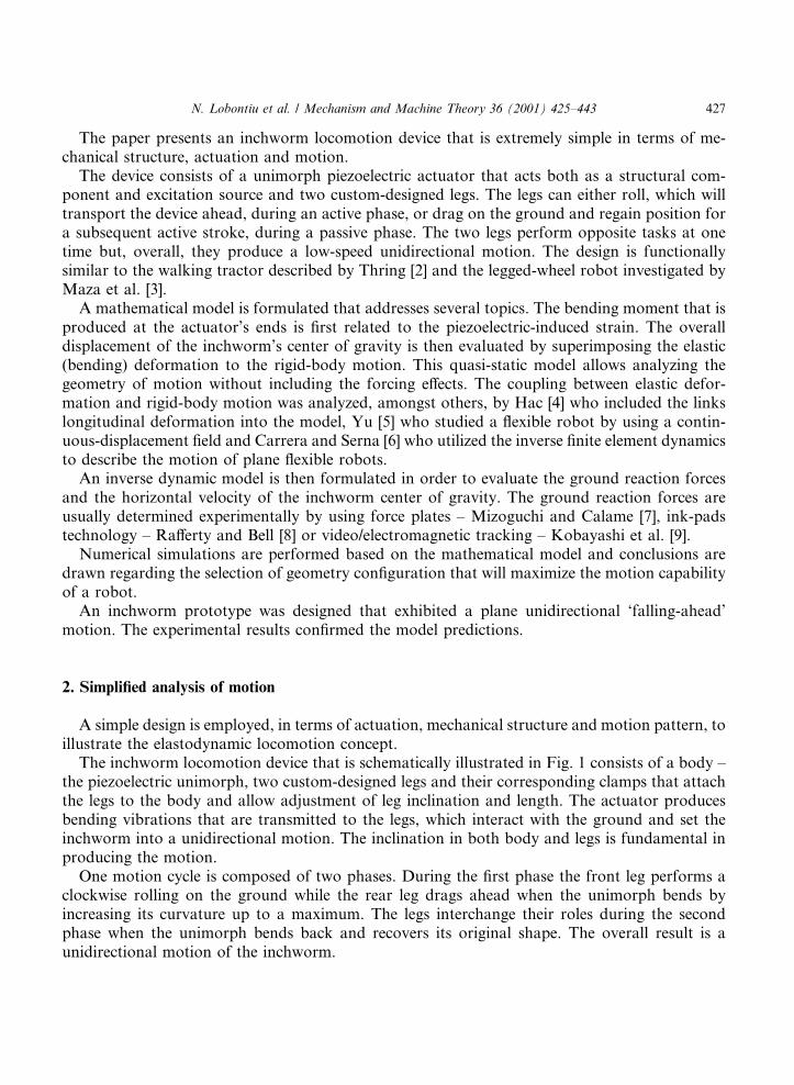
The inchworm locomotion device that is schematically illustrated in Fig. 1 consists of a body ±the piezoelectric unimorph, two custom-designed legs and their corresponding clamps that attachthe legs to the body and allow adjustment of leg inclination and length. The actuator producesbending vibrations that are transmitted to the legs, which interact with the ground and set theinchworm into a unidirectional motion. The inclination in both body and legs is fundamental inproducing the motion.
One motion cycle is composed of two phases. During the ®rst phase the front leg performs aclockwise rolling on the ground while the rear leg drags ahead when the unimorph bends byincreasing its curvature up to a maximum. The legs interchange their roles during the secondphase when the unimorph bends back and recovers its original shape. The overall result is aunidirectional motion of the inchworm.
N. Lobontiu et al. / Mechanism and Machine Theory 36 (2001) 425±443 427
A more detailed mathematical explanation of the inchworm motion is provided by Lobontiuet al. [10,11].
3. Mathematical model
A mathematical model is formulated comprising the following sections:· Forcing model: Relates the electrical input (voltage) to the mechanical output (bending mo-
ment).· Geometric model: Predicts the inchworm's center of gravity motion without including inertia
and time.· Dynamic model: Evaluates the ground reaction forces and horizontal velocity of the inch-
worm's center of gravity by including inertia and time.
3.1. Forcing model
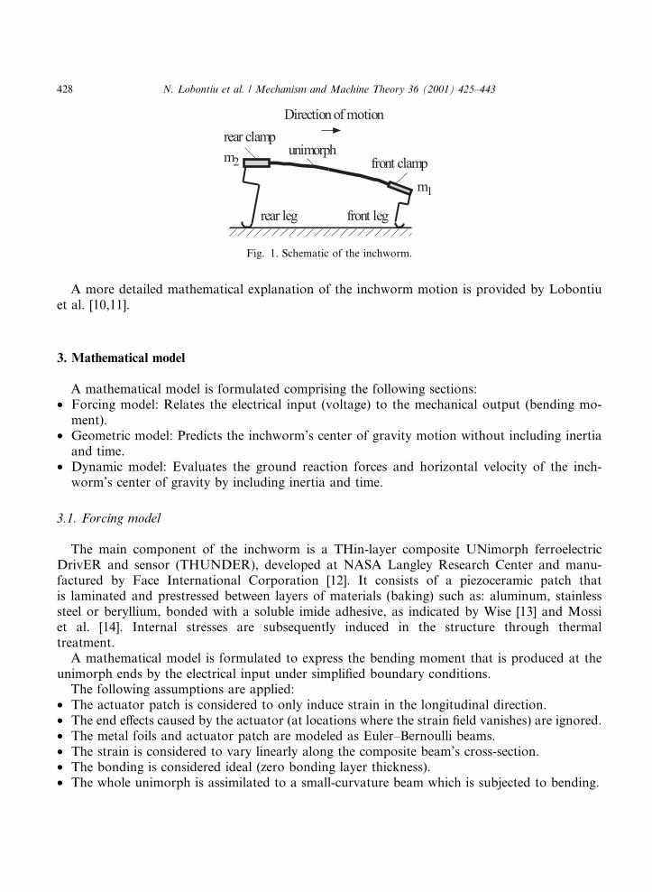
The main component of the inchworm is a THin-layer composite UNimorph ferroelectricDrivER and sensor (THUNDER), developed at NASA Langley Research Center and manu-factured by Face International Corporation [12]. It consists of a piezoceramic patch thatis laminated and prestressed between layers of materials (baking) such as: aluminum, stainlesssteel or beryllium, bonded with a soluble imide adhesive, as indicated by Wise [13] and Mossiet al. [14]. Internal stresses are subsequently induced in the structure through thermaltreatment.
A mathematical model is formulated to express the bending moment that is produced at theunimorph ends by the electrical input under simpli®ed boundary conditions.
The following assumptions are applied:· The actuator patch is considered to only induce strain in the longitudinal direction.· The end e�ects caused by the actuator (at locations where the strain ®eld vanishes) are ignored.· The metal foils and actuator patch are modeled as Euler±Bernoulli beams.· The strain is considered to vary linearly along the composite beam's cross-section.· The bonding is considered ideal (zero bonding layer thickness).· The whole unimorph is assimilated to a small-curvature beam which is subjected to bending.
Fig. 1. Schematic of the inchworm.
428 N. Lobontiu et al. / Mechanism and Machine Theory 36 (2001) 425±443

The derivation proposed here is similar to that followed by Rees [15] in analyzing thermally-induced strains.
When actuation is applied, the patch will tend to increase/decrease its length and this willproduce bending of the composite beam, as illustrated in Fig. 2. The equations that express force/moment equilibrium and strain compatibility at the two interfaces are:
Fb1 � Fa � Fb2;
Mb1 �Ma �Mb2 � Fb1
ha � hb1
2
�� ha � hb2
2
Fb2
Fb1
�;
Fb1
EbAb1
�Mb1hb1
2EbIb1
� ÿ Fa
EaAa
ÿ Maha
2EaIa
� ea;0;
ÿ Fa
EaAa
� Maha
2EaIa
� ea;0 � ÿ Fb2
EbAb2
ÿMb2hb2
2EbIb2
;
�1�
where
ea;0 � d31
Vha
�2�
and d31 is the dielectric constant.By assuming that the curvature radii of the patch and beam layers are approximately equal
yields
EaIa
Ma
� EbIb1
Mb1
� EbIb2
Mb2
: �3�
Eqs. (1) and (3) form a system of six-algebraic equations, which can be solved for the unknownsFa, Fb1, Fb2, Ma, Mb1 and Mb2.
The maximum bending moment that is generated in the beam at the patch extremities is
Mf � Mb1 �Ma �Mb2 � Cfea;0 �4�where Cf is expressed in Eqs. (A.1).
Fig. 2. Composite cross-section of the unimorph.
N. Lobontiu et al. / Mechanism and Machine Theory 36 (2001) 425±443 429
3.2. Geometric analysis of motion
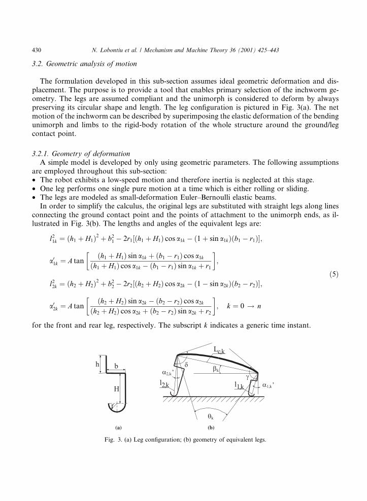
The formulation developed in this sub-section assumes ideal geometric deformation and dis-placement. The purpose is to provide a tool that enables primary selection of the inchworm ge-ometry. The legs are assumed compliant and the unimorph is considered to deform by alwayspreserving its circular shape and length. The leg con®guration is pictured in Fig. 3(a). The netmotion of the inchworm can be described by superimposing the elastic deformation of the bendingunimorph and limbs to the rigid-body rotation of the whole structure around the ground/legcontact point.
3.2.1. Geometry of deformationA simple model is developed by only using geometric parameters. The following assumptions
are employed throughout this sub-section:· The robot exhibits a low-speed motion and therefore inertia is neglected at this stage.· One leg performs one single pure motion at a time which is either rolling or sliding.· The legs are modeled as small-deformation Euler±Bernoulli elastic beams.
In order to simplify the calculus, the original legs are substituted with straight legs along linesconnecting the ground contact point and the points of attachment to the unimorph ends, as il-lustrated in Fig. 3(b). The lengths and angles of the equivalent legs are:
l21k � �h1 � H1�2 � b2
1 ÿ 2r1��h1 � H1� cos a1k ÿ �1� sin a1k��b1 ÿ r1��;
a01k � A tan�h1 � H1� sin a1k � �b1 ÿ r1� cos a1k
�h1 � H1� cos a1k ÿ �b1 ÿ r1� sin a1k � r1
� �;
l22k � �h2 � H2�2 � b2
2 ÿ 2r2��h2 � H2� cos a2k ÿ �1ÿ sin a2k��b2 ÿ r2��;
a02k � A tan�h2 � H2� sin a2k ÿ �b2 ÿ r2� cos a2k
�h2 � H2� cos a2k � �b2 ÿ r2� sin a2k � r2
� �; k � 0 ! n
�5�
for the front and rear leg, respectively. The subscript k indicates a generic time instant.
Fig. 3. (a) Leg con®guration; (b) geometry of equivalent legs.
430 N. Lobontiu et al. / Mechanism and Machine Theory 36 (2001) 425±443
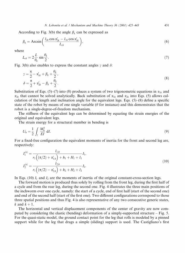
According to Fig. 3(b) the angle bk can be expressed as
bk � Arcsinl2k cos a02k ÿ l1k cos a01k
Lck
� �; �6�
where
Lck � 2Lhk
sinhk
2: �7�
Fig. 3(b) also enables to express the constant angles c and d:
c � p2ÿ a01k � bk �
hk
2;
d � p2� a02k ÿ bk �
hk
2:
�8�
Substitution of Eqs. (5)±(7) into (8) produces a system of two trigonometric equations in a1k anda2k that cannot be solved analytically. Back substitution of a1k and a2k into Eqs. (5) allows cal-culation of the length and inclination angle for the equivalent legs. Eqs. (5)±(8) de®ne a speci®cstate of the robot by means of one single variable (h for instance) and this demonstrates that therobot is a single-degree-of-freedom mechanism.
The sti�ness of the equivalent legs can be determined by equating the strain energies of theoriginal and equivalent legs.
The strain energy for a structural member in bending is
Ub � 1
2
Zl
M2b
EIdl: �9�
For a ®xed-free con®guration the equivalent moments of inertia for the front and second leg are,respectively:
I �e�1 �l1;0
r1 �p=2� � a01;0� �
� h1 � H1 � l1
I1;
I �e�2 �l2;0
r1 �p=2� ÿ a02;0� �
� h2 � H2 � l2
I2:
�10�
In Eqs. (10) I1 and I2 are the moments of inertia of the original constant-cross-section legs.The forward motion is produced thus solely by rolling from the front leg, during the ®rst half of
a cycle and from the rear leg, during the second one. Fig. 4 illustrates the three main positions ofthe inchworm over one cycle, namely: the start of a cycle, end of ®rst half (start of the second one)and end of the second half (start of the ®rst one). Two di�erent con®gurations correspond to thosethree spatial positions and thus Fig. 4 is also representative of any two consecutive generic states,k and k � 1.
The horizontal and vertical displacement components of the center of gravity are now com-puted by considering the elastic (bending) deformation of a simply-supported structure ± Fig. 5.For the quasi-static model, the ground contact point for the leg that rolls is modeled by a pinnedsupport while for the leg that drags a simple (sliding) support is used. The Castigliano's ®rst
N. Lobontiu et al. / Mechanism and Machine Theory 36 (2001) 425±443 431
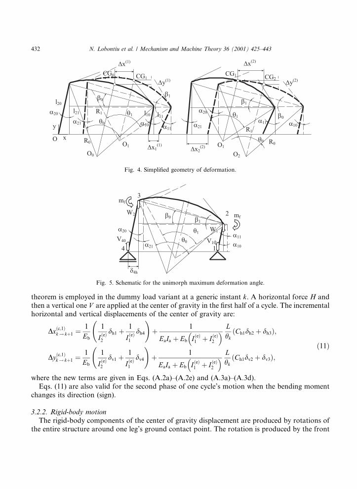
theorem is employed in the dummy load variant at a generic instant k. A horizontal force H andthen a vertical one V are applied at the center of gravity in the ®rst half of a cycle. The incrementalhorizontal and vertical displacements of the center of gravity are:
Dx�c;1�k! k�1 �1
Eb
1
I �e�2
dh1
� 1
I �e�1
dh4
!� 1
EaIa � Eb I �e�1 � I �e�2
� � Lhk�Ch1dh2 � dh3�;
Dy�c;1�k! k�1 �1
Eb
1
I �e�2
dv1
� 1
I �e�1
dv4
!� 1
EaIa � Eb I �e�1 � I �e�2
� � Lhk
Ch1dv2� � dv3�;�11�
where the new terms are given in Eqs. (A.2a)±(A.2e) and (A.3a)±(A.3d).Eqs. (11) are also valid for the second phase of one cycle's motion when the bending moment
changes its direction (sign).
3.2.2. Rigid-body motionThe rigid-body components of the center of gravity displacement are produced by rotations of
the entire structure around one leg's ground contact point. The rotation is produced by the front
Fig. 4. Simpli®ed geometry of deformation.
Fig. 5. Schematic for the unimorph maximum deformation angle.
432 N. Lobontiu et al. / Mechanism and Machine Theory 36 (2001) 425±443
leg during the ®rst phase of a cycle and then by the rear one during the second phase. Simplegeometric considerations allow formulating the incremental displacement components of thecenter of gravity and rotation radius during the ®rst phase as:
Dx�rb;1�k! k�1 � 2R1;k sin
a01;k�1 ÿ a01;k2
cos n1;k
ÿ a01;k�1 ÿ a01;k
2
!;
Dy�rb;1�k! k�1 � 2R1;k sin
a01;k�1 ÿ a01;k2
sin n1;k
ÿ a1;k�1 ÿ a01;k
2
!;
�12�
where
R1;k �������������������������������������������������������������������������������������������������������������������l2
1;k � 4L2
h2k
sin2 hk
4ÿ 2l1;k
Lhk
sinhk
4sin a01;k ÿ b0k �
hk
4
� �� �s;
n1;k � Arcsin 2L
hkR1;ksin
hk
4cos a01;k
��ÿ bk
�� hk
4
���:
�13�
The same amounts are computed in a similar manner for the second phase, namely:
Dx�rb;2�k! k�1 � 2R2;k sin
a02;k�1 ÿ a02;k2
cos n2;k
� a02;k�1 ÿ a02;k
2
!;
Dy�rb;2�k! k�1 � ÿ2R2;k sin
a02;k�1 ÿ a02;k2
sin n2;k
� a02;k�1 ÿ a02;k
2
! �14�
with
R2;k �������������������������������������������������������������������������������������������������������������������l2
2;k � 4L2
h2k
sin2 hk
4ÿ 2l2;k
Lhk
sinhk
4sin bk ÿ a02;k �
hk
4
� �� �s;
n2;k � Arcsin 2L
hkR2;ksin
hk
4cos bk
��ÿ a02;k
�� hk
4
���:
�15�
The total displacement components of the center of gravity are calculated by summing thecompliant and rigid-body components, namely
Dq�i�k! k�1 � Dq�c;i�k! k�1 � Dq�rb;i�k! k�1; q � x; y; i � 1; 2: �16�
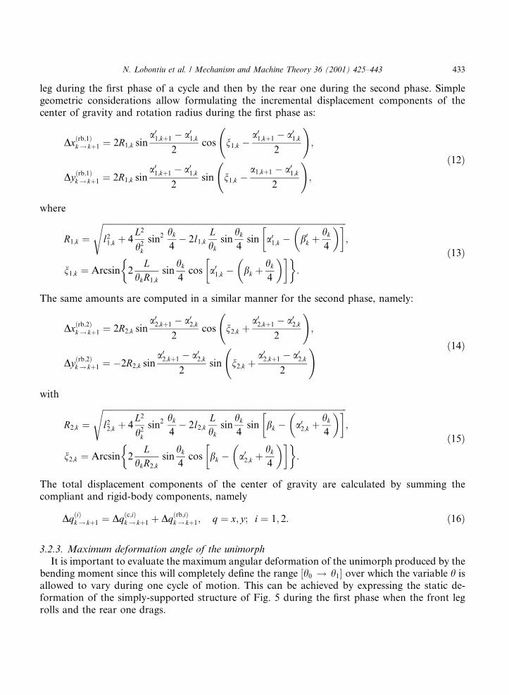
3.2.3. Maximum deformation angle of the unimorphIt is important to evaluate the maximum angular deformation of the unimorph produced by the
bending moment since this will completely de®ne the range �h0 ! h1� over which the variable h isallowed to vary during one cycle of motion. This can be achieved by expressing the static de-formation of the simply-supported structure of Fig. 5 during the ®rst phase when the front legrolls and the rear one drags.
N. Lobontiu et al. / Mechanism and Machine Theory 36 (2001) 425±443 433
The Castigliano's ®rst theorem is applied to compute d4h, the horizontal displacement of point 4(Fig. 5), by means of a dummy horizontal load H40 �H40 � 0� and by applying the maximum valueof the bending moment produced by the unimorph, Mf
d4h � d�rb�4h �
1
Eb
1
I �e�1
C0h5
� 1
I �e�2
C0h6
!; �17�
where d�rb�4h , the horizontal displacement of a rigid-legs inchworm, is calculated by using Eqs. (11)
and is of the form
d�rb�4h �
1
EaIa � Eb Ib1 � Ib2� �Lh0
C0h1h0
�� C0h2�1ÿ cos h0� � C0h3 sin h0 � C0h4
1ÿ cos 2h0
2
�: �18�
The new symbols in Eqs. (17) and (18) are given in Eqs.(A.4) and (A.5). The assumption is appliedhere that the unimorph tabs have zero length and therefore the curved beam has constant-thickness cross-section over its whole length.
Eqs. (17) and (18), together with Eqs. (A.4) and (A.5) illustrate that
d4h � fd�Mf�: �19�Simple geometric considerations indicate that the horizontal displacement of the rear leg shouldcomply with
d4h � l21 sin a021 � Lc1 cos b1 ÿ l11 sin a011 � l20 sin a020 � Lc0 cos b0 ÿ l10 sin a010 �20�which shows that h1 can be expressed as a function of h0 and Mf only.
3.2.4. Dynamic modelThe motion has been analyzed so far by only considering the geometry of deformation and
rigid-body motion, which enabled to formulate a single-degree of freedom model. Inertia and timeare now included into a lumped-parameter model that is used to derive the dynamic equations ofmotion for the inchworm center of gravity with respect to a ®xed reference frame as shown inFig. 4. The interval �h0; h1� is univocally related to the time interval �t0; t1�. The mass of the legs isneglected and the mass of the system is concentrated at the center of gravity. Since the clampshave masses that are approximately equal and the angle h is relatively small, it is considered thatthe center of gravity is placed at the unimorph midpoint.
Newton's second law is applied for the x, y and z axes and the corresponding equations are:
M�x�1� � lGRF�1�1 ÿ lGRF
�1�2 ;
M�y�1� � GRF�1�1 �GRF
�1�2 ÿMg;
2ML2
h20
�b�1� � GRF�1�1 l1;k sin a01;k
�� Lc;k
2cos bk
�ÿGRF
�1�2 l2;k sin a02;k
�� Lc;k
2cos bk
�ÿ lGRF
�1�1 l1;k cos a01;k
�� Lc;k
2sin bk
�ÿ lGRF
�1�2 l2;k cos a02;k
�ÿ Lc;k
2sin bk
��21�
for the ®rst half of a cycle. A similar equation can be written for the second half by changing thesign of the friction force in Eqs. (21).
434 N. Lobontiu et al. / Mechanism and Machine Theory 36 (2001) 425±443
The central di�erence scheme is now utilized to express the acceleration in terms of displace-ment components
�qk � qk�1 ÿ 2qk � qkÿ1
Dt2; q � x; y;b; k � 1 ! n; �22�
where Dt is the time step.Eqs. (21) are discretized with respect to time at the station k and their solutions are:
GRF�i�1;k �
D�i�1;k
D�i�2;k
Mg
GRF�i�2;k �
D�i�3;k
D�i�2;k
Mg
Dt�i�k ���������������������������������������������������������������
d�i�1;k
�ÿ1�i�1GRF
�i�1;k � �ÿ1�iGRF
�i�2;k
vuut ; i � 1; 2:
�23�
(A.6a)±(A.6c) gives the new amounts of Eqs. (23).The time step might vary as indicated by Eqs. (23). In order to ensure numerical accuracy, the
minimum value was taken to be the actual time step.
4. Numerical simulation and design
Preliminary simulation was ®rst performed in order to select the geometry con®guration that iscapable of maximizing the robot performance. An inchworm prototype was designed based onthis data. Subsequent numerical simulation addressed the ground reaction forces and the hori-zontal velocity for the prototype's center of gravity.
4.1. Preliminary simulation
The purpose was to enable primary selection of the geometric parameters that could maximizethe deformation angle of the unimorph, h1 and the horizontal displacement of the inchwormcenter of gravity, Dx.
The following conclusions were derived with reference to Fig. 6(a)±(e):· The parameters r1; r2;H1;H2; h1 and h2 have little in¯uence on h1, as illustrated in Fig. 6(a) and
(b), for instance.· The inclination angle of the front leg, a10, should be small (approaching zero, as indicated
by Fig. 6(a)) while the inclination angle of the rear leg, a20, should be large, as suggested byFig. 6(b).
· The angles d and c that de®ne the unimorph-legs relative position need to be small as shown inFig. 6(c).
· Fig. 6(d) indicates that more mass is needed to the rear of the device.
N. Lobontiu et al. / Mechanism and Machine Theory 36 (2001) 425±443 435
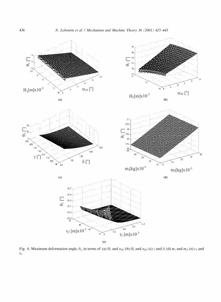
Fig. 6. Maximum deformation angle, h1, in terms of: (a) H1 and a10; (b) H2 and a20; (c) c and d; (d) m1 and m2; (e) c2 and
t2.
436 N. Lobontiu et al. / Mechanism and Machine Theory 36 (2001) 425±443
· For values in a practical range, the legs cross-sectional parameters have little in¯uence on h1,except for small values that are likely to increase h1, as illustrated in Fig. 6(e) for instance.Similar conclusions were drawn with regard to the horizontal displacement of the robot's center
of gravity.
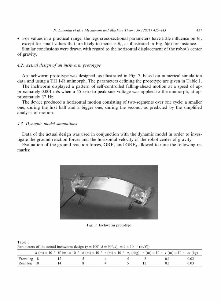
4.2. Actual design of an inchworm prototype
An inchworm prototype was designed, as illustrated in Fig. 7, based on numerical simulationdata and using a TH 1-R unimorph. The parameters de®ning the prototype are given in Table 1.
The inchworm displayed a pattern of self-controlled falling-ahead motion at a speed of ap-proximately 0.001 m/s when a 45 zero-to-peak sine-voltage was applied to the unimorph, at ap-proximately 37 Hz.
The device produced a horizontal motion consisting of two-segments over one cycle: a smallerone, during the ®rst half and a bigger one, during the second, as predicted by the simpli®edanalysis of motion.
4.3. Dynamic model simulations
Data of the actual design was used in conjunction with the dynamic model in order to inves-tigate the ground reaction forces and the horizontal velocity of the robot center of gravity.
Evaluation of the ground reaction forces, GRF1 and GRF2 allowed to note the following re-marks:
Fig. 7. Inchworm prototype.
Table 1
Parameters of the actual inchworm design (c � 100°; d � 90°; d31 � 9� 10ÿ11 (m/V))
h �m� � 10ÿ3 H �m� � 10ÿ3 b �m� � 10ÿ3 r �m� � 10ÿ3 a0 (deg) c �m� � 10ÿ3 t �m� � 10ÿ3 m (kg)
Front leg 8 12 5 4 5 8 0.1 0.02
Rear leg 10 14 8 4 5 12 0.1 0.03
N. Lobontiu et al. / Mechanism and Machine Theory 36 (2001) 425±443 437
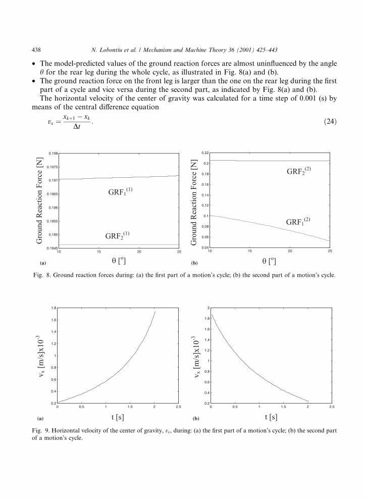
· The model-predicted values of the ground reaction forces are almost unin¯uenced by the angleh for the rear leg during the whole cycle, as illustrated in Fig. 8(a) and (b).
· The ground reaction force on the front leg is larger than the one on the rear leg during the ®rstpart of a cycle and vice versa during the second part, as indicated by Fig. 8(a) and (b).The horizontal velocity of the center of gravity was calculated for a time step of 0.001 (s) by
means of the central di�erence equation
vx � xk�1 ÿ xk
Dt: �24�
Fig. 9. Horizontal velocity of the center of gravity, vx, during: (a) the ®rst part of a motion's cycle; (b) the second part
of a motion's cycle.
Fig. 8. Ground reaction forces during: (a) the ®rst part of a motion's cycle; (b) the second part of a motion's cycle.
438 N. Lobontiu et al. / Mechanism and Machine Theory 36 (2001) 425±443
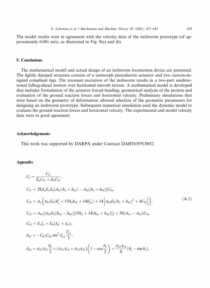
The model results were in agreement with the velocity data of the inchworm prototype (of ap-proximately 0.001 m/s), as illustrated in Fig. 9(a) and (b).
5. Conclusions
The mathematical model and actual design of an inchworm locomotion device are presented.The lightly damped structure consists of a unimorph piezoelectric actuator and two custom-de-signed compliant legs. The resonant excitation of the inchworm results in a two-part unidirec-tional falling-ahead motion over horizontal smooth terrain. A mathematical model is developedthat includes formulation of the actuator forced bending, geometrical analysis of the motion andevaluation of the ground reaction forces and horizontal velocity. Preliminary simulations thatwere based on the geometry of deformation allowed selection of the geometric parameters fordesigning an inchworm prototype. Subsequent numerical simulation used the dynamic model toevaluate the ground reaction forces and horizontal velocity. The experimental and model velocitydata were in good agreement.
Acknowledgements
This work was supported by DARPA under Contract DABT6397C0052.
Appendix
Cf � Cf1
EaCf2 � EbCf3
;
Cf1 � 28AaEaEb Ab1�ha� � hb1� ÿ Ab2�ha � hb2��Cf4;
Cf2 � Aa Ab1Eb�h2a
n� 15hahb1 � 14h2
b1� � 14 Ab2Eb�ha
h� hb2�2 � 4Cf4
io;
Cf3 � Ab1 Ab2Eb�hb2f ÿ hb1� 15ha� � 14�hb1 � hb2��g � 56 Ab1� ÿ Ab2�Cf4;
Cf4 � EaIa � Eb Ib1� � Ib2�;
�A:1�
dh1 �ÿCh1Ch2 sin2 a02;kl3
2;k
3;
dh2 � A21A23
hk
2� �A21A24�A22A23� 1
�ÿ cos
hk
2
��A22A24
4�hk ÿ sinhk�;
N. Lobontiu et al. / Mechanism and Machine Theory 36 (2001) 425±443 439
dh3 � A21A33
hk
2ÿ �A21A34�A22A33� coshk
�ÿ cos
hk
2
�ÿA22A24
4cos bk
�ÿ hk
2
�cos 2hk� ÿ coshk�
�A22
4�hk ÿ sin 2hk � sinhk� A34
�ÿA24 sin bk
�ÿ hk
2
��
�A21A24 cos bk
��ÿ hk
2
�coshk
�ÿ cos
hk
2
�� sin bk
�ÿ hk
2
�sinhk
�ÿ sin
hk
2
��;
dh4 � l1;k A41A43� � �A41A44�A42A43
2l1;k �A42A44
3l2
1;k;
�A:2a�
A21 � mf;k ÿ Ch2l2;k sin a02;k;
A22 � m2gLhkÿ Ch2
Lhk;
A23 � l2;k sin a02;k;
A24 � Lhk;
�A:2b�
A33 � Ch1l2;k sin a02;k ÿLhk
cos bk;
A34 � Ch1
Lhk;
�A:2c�
A41 � m2gLc;k cos bk ÿ Ch1�l2;k sin a02;k � Lc;k cos bk�;
A42 � �Ch2 ÿ �m1 � m2�g� sin a01;k;
A43 � Ch1 l2;k sin a02;k�
� Lc;k cos bk
�ÿ L
hkcos bk
�� cos bk
�� hk
2
��;
A44 � ÿ�Ch1 sin a01;k � cos a01;k�;
�A:2d�
Ch1 ��L=hk� cos bk ÿ cos bk � �hk=2�� �� � � l1;k cos a01;k
Lc;k cos bk � l2;k sin a02;k ÿ l1;k sin a01;k;
Ch2 �m2Lc;k cos bk ÿ �m1 � m2�l1;k sin a01;kLc;k cos bk � l2;k sin a02;k ÿ l1;k sin a01;k
g;
�A:2e�
440 N. Lobontiu et al. / Mechanism and Machine Theory 36 (2001) 425±443
dv1 �ÿCh2Cv3 sin2 a02;kl3
2;k
3;
dv2 � dh2;
dv3 � A21A36
hk
2ÿ �A21A37�A22A36� coshk
�ÿ cos
hk
2
��A22A24
4sin bk
�ÿ hk
2
��cos 2hk ÿ coshk�
�A22
4hk� ÿ sin 2hk � sinhk� A37
�ÿA24 cos bk
�ÿ hk
2
��
ÿA21A24 sin bk
��ÿ hk
2
�sinhk
�ÿ sin
hk
2
�ÿ cos bk
�ÿ hk
2
�coshk
�ÿ cos
hk
2
��;
d4v � l1;k A41A45
��A41A46�A42A45
2l1;k �A42A46
3l2
1;k
�;
�A:3a�
A36 � Ch3l2;k sin a02;k �Lhk
cos bk;
A37 � Ch1
Lhk;
�A:3b�
A45 � Cv3 l2;k sin a02;k�
� Lc;k cos bk
�ÿ L
hksin bk
��� hk
2
�ÿ sin bk
�;
A46 � �1ÿ Cv3� sin a01;k;�A:3c�
Cv3 ��L=hk� sin bk � �hk=2�� � ÿ sin bk� � ÿ l1;k sin a01;k
Lc;k cos bk � l2;k sin a02;k ÿ l1;k sin a01;k; �A:3d�
C0h1 � Mf� ÿ V40l20 sin a20� l20 cos a20
�ÿ L
h0
�;
C0h2 � �m2g ÿ V40� Lh0
l20 cos a20
�ÿ L
h0
�;
C0h3 � �Mf ÿ V40l20 sin a20� Lh0
;
C0h4 �1
2m2g� ÿ V40� L
2
h20
;
�A:4�
N. Lobontiu et al. / Mechanism and Machine Theory 36 (2001) 425±443 441
C0h5 � l10 C0h7C0h8
�� C0h7C0h9 ÿ C0h8 cos a010
2l10 ÿ C0h9 cos a010
3l2
10
�;
C0h6 � ÿl3
20
6V40 sin a020;
C0h7 � l20 cos a020 ÿ Lc;0 sin b0;
C0h8 � ÿ�V40 � m2g�C0h10;
C0h9 � �V40 ÿ m1g� sin a010;
C0h10 � l20 sin a020 � Lc;0 cos b0;
�A:5�
D�1�1;k � d�1�1;k d5;k
�ÿ d�1�1;k d�1�4;k
�;
D�1�2;k � d�1�1;k
�ÿ d�1�2;k
�d5;k
�ÿ d�1�1;k d�1�4;k
�� d�1�1;k
�� d�1�2;k
�d5;k
�ÿ d�1�1;k d�1�3;k
�;
D�1�3;k � d�1�1;k d5;k
�ÿ d�1�1;k d�1�3;k
�;
�A:6a�
D�2�1;k � d�2�1;k d5;k
�� d�2�1;k d�2�4;k
�;
D�2�2;k � d�2�1;k
�ÿ d�2�2;k
�d5;k
�� d�2�1;k d�2�3;k
�� d�2�1;k
�� d�2�2;k
�d5;k
�� d�2�1;k d�2�4;k
�;
D�2�3;k � d�2�1;k d5;k
�� d�2�1;k d�2�3;k
�;
�A:6b�
d�i�1;k �Ml
x�i�k�1
�ÿ 2x�i�k � x�i�kÿ1
�;
d�i�2;k � M y�i�k�1
�ÿ 2y�i�k � y�i�kÿ1
�;
d�i�3;k � l1;k sin a01;k �Lc;k
2cos bk ÿ l l1;k cos a01;k
�� Lc;k
2sin bk
�;
d�1�4;k � l2;k sin a02;k �Lc;k
2cos bk � l l2;k cos a01;k
�ÿ Lc;k
2sin bk
�;
d�2�4;k � l2;k sin a02;k �Lc;k
2cos bk � l l2;k cos a01;k
�ÿ Lc;k
2sin bk
�;
d5;k � I bk�1
ÿ ÿ 2bk � bkÿ1
�; i � 1; 2:
�A:6c�
References
[1] V.I. Babitsky, M.Y. Chitayev, Adaptive high-speed resonant robot, Mechatronics 6 (8) (1996) 897±913.
[2] M.W. Thring, Robots and Telechirs, Ellis Horwood, Chichester, 1983, pp. 134±181.
442 N. Lobontiu et al. / Mechanism and Machine Theory 36 (2001) 425±443

[3] M. Maza, J.G. Fontaine, M. Armada, P. Gonzales de Santos, V. Papantoniou, P. Mas, Wheels� legs ± a new
solution for traction enhancement without additive soil compaction, IEEE Robotics & Automation Magazine 12
(1997) 26±33.
[4] M. Hac, Dynamics of ¯exible mechanisms with mutual dependence between rigid body motion and longitudinal
deformation of links, Mechanism and Machine Theory 30 (6) (1995) 837±847.
[5] W. Yu, Mathematical modeling for a class of ¯exible robot, Applied Mathematical Modelling 19 (1995) 537±542.
[6] E. Carrera, M.A. Serna, Inverse dynamics of ¯exible robots, Mathematics and Computers in Simulation 41 (1996)
485±508.
[7] M. Mizoguchi, C. Calame, Possibilities and limitations of today's force plate technology, Gait and Posture 3 (1995)
268.
[8] D. Ra�erty, F. Bell, Gait analysis a ± semiautomated approach, Gait and Posture 3 (3) (1995) 184±185.
[9] K. Kobayashi, L. Gransberg, E. Knutsson, P. Nolen, A new system for three-dimensional gait recording using
electromagnetic tracking, Gait and Posture 6 (1) (1997) 63±75.
[10] N. Lobontiu, M. Goldfarb, E. Garcia, Analysis and design approach to inchworm robotic insects, in: Proceedings
of IEEE International Conference on Robotics and Automation, Detroit, 1999, pp. 2020±2025.
[11] N. Lobontiu, M. Goldfarb, E. Garcia, Elastodynamic analysis and design of an inchworm robotic insect, in: N.M.
Wereley (Ed.), Proceedings of SPIE 3668 (1999) 724±737; Symposium on Smart Structures and Materials 99: Smart
Structures and Integrated Systems, Newport Beach.
[12] Face International Corporation, Preliminary THUNDERe Speci®cations (1997).
[13] S.A. Wise, Displacement properties of RAINBOW and THUNDER piezoelectric actuators, Sensors and Actuators
A 69 (1998) 33±38.
[14] K.A. Mossi, G.V. Selby, R.G. Bryant, Thin-layer composite unimorph ferroelectric driver and sensor properties,
Material Letters 35 (1998) 39±49.
[15] D.W.A. Rees, Basic Solid Mechanics, Macmillan, London, 1997.
N. Lobontiu et al. / Mechanism and Machine Theory 36 (2001) 425±443 443