a plane vibration model for natural vibration analysis of soft
TRANSCRIPT

14
A Plane Vibration Model for Natural Vibration Analysis of Soft Mounted Electrical Machines
Ulrich Werner Siemens AG, Industry Drive Technologies, Large Drives, Products Development
Germany
1. Introduction
Large electrical machines, which operate at high speeds, are often designed with flexible shafts and sleeve bearings, because of the high circumferential speed of the shaft journals. Especially for industrial applications, the foundations of this kind of machines are often designed as soft foundations (Fig. 1), because of plant specific requirements. Therefore often a significant influence of the soft foundation on the vibrations exists (Gasch et al., 1984; Bonello & Brennan, 2001). Additionally to the mechanical parameters – such as e.g. mass, mechanical stiffness and damping – an electromagnetic field in the electrical machine exists, which causes an electromagnetic coupling between rotor and stator and also influences the natural vibrations (Schuisky, 1972; Belmans et al., 1987; Seinsch, 1992; Arkkio et al., 2000; Holopainen, 2004; Werner, 2006). The aim of the chapter is to show a plane vibration model for natural vibration analysis, of soft mounted electrical machines, with flexible shafts and sleeve bearings, especially considering the influence of a soft foundation and the electromagnetic field. Based on a simplified plane vibration model, the mathematical correlations between the rotor and the stator movement, the sleeve bearings, the electromagnetic field and the foundation, are shown. For visualization, the natural vibrations of a soft mounted 2-pole induction motor (rated power: 2 MW) are analyzed exemplary, especially focusing on the influence of the foundation, the oil film stiffness and damping and of the electromagnetic field.
z
yx
Stator with
end shields
Soft foundation
Sleeve
bearing
b
h
b
Sleeve
bearing
Rotor
StatorSleeve
bearing
End
shieldEnd shield
Drive side Non drive side
Shaft
end Ω
Soft foundation
z
yx
Stator with
end shields
Soft foundation
Sleeve
bearing
b
h
b
Sleeve
bearing
Rotor
StatorSleeve
bearing
End
shieldEnd shield
Drive side Non drive side
Shaft
end Ω
Soft foundation
Fig. 1. Induction motor (2-pole), mounted on a soft foundation
www.intechopen.com

Advances in Vibration Analysis Research
274
2. Vibration model
The vibration model is a simplified plane model (Fig. 2), describing the natural vibrations in
the transversal plane (plane y, z) of a soft mounted electrical machine. Therefore no natural
vibrations regarding the translation in the x-axis, the rotation at the y-axis and the rotation at
the z-axis are considered. The plane model is based on the general models in (Werner, 2008;
Werner, 2010), but especially focusing here on the natural vibration analysis.
W,V yw, yv
..
Szb
cfz Boreholes
of the
machine feet
cfz
⎥⎥⎦⎤
⎢⎢⎣⎡=
yyyz
zyzz
vdd
ddD
Rotor mass mw
Stator: mass ms
and inertia Θsx
yb
Oil film stiffness
matrix:
⎥⎥⎦⎤
⎢⎢⎣⎡=
yyyz
zyzz
vcc
ccC
Oil film damping
matrix:
zs⎥⎦⎤⎢⎣
⎡=by
bz
b0
0
c
cC
ys
yfL
yfR
zfL zfR
dfz
cfy
dfy
cfy
dfy
h
bb
ϕs
Bearing house
and end shield
stiffness matrix:
Rigid bar
a) View from x (shaft end)
dfz
FLFR
zw,zv.
.... . . .
Note: Magnetic
spring cm is not
pictured in
that view
Ω
.
yfL yfR
ys
zb
yv
zv
zb
yb
zs
zw
Rotor stiffness c
vC
vD
ϕsRigid bar Rigid bar
bC
vD
bC
vC
zv
yv
yb
zfL, zfR
Magnetic
spring
matrix:
W
S
Rigid bar
mw
ms,Θsx ⎥⎦⎤⎢⎣
⎡=m
m
m0
0
c
cC
Foundation
stiffness matrix:
⎥⎦⎤⎢⎣
⎡=fy
fz
f 0
0
c
cC
Foundation
damping matrix:
⎥⎦⎤⎢⎣
⎡=fy
fz
f 0
0
d
dD
V V
B B
FRFL
yw
. .
.
. . . .
. .
b) View from y
Ω.
Ψ
B
Fig. 2. Vibration model of a soft mounted electrical machine
The model consists of two masses, rotor mass mw, concentrated at the shaft – rotating with
angular frequency Ω – and stator mass ms, which has the inertia θsx and is concentrated at
the centre of gravity S. The moments of inertia of the rotor are not considered and therefore
no gyroscopic effects. Shaft journal centre point V describes the movement of the shaft
journal in the sleeve bearing. Point B is positioned at the axial centre of the sleeve bearing
shell and describes the movement of the bearing housing. The rotor mass is mechanically
linked to the stator mass by the stiffness of rotor c and the oil film stiffness matrix Cv and the
oil film damping matrix Dv of the sleeve bearings, which contain the oil film stiffness
coefficients (cyy, cyz, czy, czz) and the oil film damping coefficients (dyy, dyz, dzy, dzz) (Fig. 3).
The cross-coupling coefficients – stiffness cross-coupling coefficients cyz, czy and damping
cross-coupling coefficients dyz, dzy – cause a coupling between vertical and horizontal
movement and the vertical oil film force Fz and the horizontal oil film forces Fy (Tondl, 1965;
Glienicke, 1966; Lund & Thomsen, 1978; Lund & Thomsen, 1987; Gasch et al. 2002; Vance et
al., 2010), which is mathematically described in (1).
www.intechopen.com

A Plane Vibration Model for Natural Vibration Analysis of Soft Mounted Electrical Machines
275
⎥⎦⎤⎢⎣
⎡−−⋅⎥⎥⎦
⎤⎢⎢⎣⎡+⎥⎦
⎤⎢⎣⎡
−−⋅⎥⎥⎦
⎤⎢⎢⎣⎡=⎥⎦
⎤⎢⎣⎡
byy
zz
dd
dd
yy
zz
cc
cc
F
F
$$$$
v
bv
yyyz
zyzz
bv
bv
yyyz
zyzz
y
z (1)
For cylindrical shell bearings the cross-coupling stiffness coefficients are usually not equal (czy ≠ cyz). This leads to an asymmetric oil film stiffness matrix Cv, which is the reason that vibration instability may occur (Tondl, 1965; Glienicke, 1966; Lund & Thomsen, 1978; Lund & Thomsen, 1987; Gasch et al. 2002; Vance et al., 2010). In this model it is assumed that the drive side and the non drive side values are the same, and the bearing housing and end shield stiffness matrix Cb is also assumed to be same for the drive side and non drive side. The stiffness and damping values of the oil film are calculated by solving the Reynolds-differential equation, using the radial bearing forces, which are caused by the rotor weight and static magnetic pull. The stiffness and damping values of the oil film are assumed to be linear regarding the displacements of the shaft journals relative to the bearing housings.
⎥⎥⎦⎤
⎢⎢⎣⎡=
yyyz
zyzz
vdd
ddD
⎥⎥⎦⎤
⎢⎢⎣⎡=
yyyz
zyzz
vcc
ccC
Oil film stiffness matrix:
Oil film damping matrix:
yzyy ;dd
yzyy ;cc
zyzz ;ddzyzz ;cc
yv
zv
Journal shaft
V
Fz
Fyg
yb
zb
⎥⎥⎦⎤
⎢⎢⎣⎡=
yyyz
zyzz
vdd
ddD
⎥⎥⎦⎤
⎢⎢⎣⎡=
yyyz
zyzz
vcc
ccC
Oil film stiffness matrix:
Oil film damping matrix:
yzyy ;dd
yzyy ;cc
zyzz ;ddzyzz ;cc
yv
zv
Journal shaft
V
Fz
Fyg
yb
zb
Fig. 3. Oil film forces
Damping of the bearing housings and the end shields are not considered because of the usually low damping ratio. For electrical machines, an additional magnetic stiffness matrix Cm between the rotor and the stator exists, which describes the electromagnetic coupling between the rotor and stator. The magnetic spring constant cm has a negative reaction. This means that a radial movement between the rotor and stator creates an electromagnetic force that tries to magnetize the movement (Schuisky, 1972; Belmans et al., 1987; Seinsch, 1992; Arkkio et al., 2000; Holopainen, 2004; Werner, 2006). Here the magnetic spring coefficient cm is defined to be positive, which acts in the direction of the magnetic forces. Electromagnetic field damping effects, e.g. by the rotor cage of an induction motor, are not considered in this paper. The stator structure is assumed to be rigid when compared to the soft foundation. The foundation stiffness matrix Cf and the foundation damping matrix Df connect the stator feet, FL (left side) and FR (right side), to the ground. The foundation stiffness and damping on the right side is assumed to be the same as on the left side. The stiffness values cfy and cfz and the damping values dfy and dfz are the values for each machine side. The coordinate systems for V (zv; yv) and B (zb; yb) have the same point of origin, as well as the coordinate systems for the stator mass ms (zs; ys) and for the rotor mass mw (zw; yw). They are only shown with an offset to show the connections through the various spring and damping elements.
3. Natural vibrations
To calculate the natural vibrations, it is necessary to derive the homogenous differential equation, which is assumed to be linear.
www.intechopen.com

Advances in Vibration Analysis Research
276
3.1 Derivation of the homogenous differential equation system
The homogenous differential equation system can be derived by separating the vibration system into four single systems – (a) rotor mass system, (b) journal system, (c) bearing house system and (d) stator mass system – (Fig. 4).
Www ym $$⋅ww zm $$⋅ ( )vzzc w −
( )vyyc w − ( )sm zzc w −( )sm yyc w −
zv
yv
V( )v
2yy
cw −
( )v2
zzc
w −
( ) ( )( ) ( )bvzybvzz
bvzybvzz
yydzzd
yyczzc
$$$$ −+−++−+−
( ) ( )( ) ( )bvyybvyz
bvyybvyz
yydzzd
yyczzc
$$$$ −+−++−+−
zb
yb
B
( )sbbz zzc −
( ) ( )( ) ( )bvzybvzz
bvzybvzz
yydzzd
yyczzc
$$$$ −+−++−+−
( ) ( )( ) ( )bvyybvyz
bvyybvyz
yydzzd
yyczzc
$$$$ −+−++−+−( )sbby yyc −
(a) Rotor mass system
(b) Journal system:
(c) Bearing house system:
zw
yw
S
yfL
zfL
zs
ys
yfR
zfR
sϕ$$⋅Θsx
ss zm $$⋅( )sm zzc w −
( )sbbz2 zzc −
ss ym $$⋅( )sm yyc w −
( )sbby2 yyc −
fLfy yd $⋅fLfy yc ⋅
fLfz zc ⋅fLfz zd $⋅ fRfy yd $⋅
fRfy yc ⋅
fRfz zc ⋅fRfz zd $⋅
(d) Stator mass system:
ϕs
FL
FR
Www ym $$⋅ww zm $$⋅ ( )vzzc w −
( )vyyc w − ( )sm zzc w −( )sm yyc w −
zv
yv
zv
yv
V( )v
2yy
cw −
( )v2
zzc
w −
( ) ( )( ) ( )bvzybvzz
bvzybvzz
yydzzd
yyczzc
$$$$ −+−++−+−
( ) ( )( ) ( )bvyybvyz
bvyybvyz
yydzzd
yyczzc
$$$$ −+−++−+−
zb
yb
zb
yb
B
( )sbbz zzc −
( ) ( )( ) ( )bvzybvzz
bvzybvzz
yydzzd
yyczzc
$$$$ −+−++−+−
( ) ( )( ) ( )bvyybvyz
bvyybvyz
yydzzd
yyczzc
$$$$ −+−++−+−( )sbby yyc −
(a) Rotor mass system
(b) Journal system:
(c) Bearing house system:
zw
yw
zw
yw
S
yfL
zfL
zs
ys
yfR
zfR
sϕ$$⋅Θsx
ss zm $$⋅( )sm zzc w −
( )sbbz2 zzc −
ss ym $$⋅( )sm yyc w −
( )sbby2 yyc −
fLfy yd $⋅fLfy yc ⋅
fLfz zc ⋅fLfz zd $⋅ fRfy yd $⋅
fRfy yc ⋅
fRfz zc ⋅fRfz zd $⋅
(d) Stator mass system:
ϕs
FL
FR
Fig. 4. Vibration system, split into four single systems
The equilibrium of forces and moments for each single system (Fig. 4) leads to following equations for each single system: - Rotor mass system (Fig. 4a):
|: ( ) ( ) 0swmvwww =−⋅−−⋅+⋅ zzczzczm $$ (2)
: ( ) ( ) 0swmvwww =−⋅−−⋅+⋅ yycyycym $$ (3)
- Journal system (Fig. 4b):
|: ( ) ( ) ( ) ( ) ( ) 02
vwbvzybvzzbvzybvzz =−−−+−+−+− zzc
yydzzdyyczzc $$$$ (4)
: ( ) ( ) ( ) ( ) ( ) 02
vwbvyybvyzbvyybvyz =−−−+−+−+− yyc
yydzzdyyczzc $$$$ (5)
- Bearing house system (Fig. 4c):
|: ( ) ( ) ( ) ( ) ( ) 0sbbzbvzybvzzbvzybvzz =−⋅−−+−+−+− zzcyydzzdyyczzc $$$$ (6)
: ( ) ( ) ( ) ( ) ( ) 0sbbybvyybvyzbvyybvyz =−⋅−−+−+−+− yycyydzzdyyczzc $$$$ (7)
www.intechopen.com

A Plane Vibration Model for Natural Vibration Analysis of Soft Mounted Electrical Machines
277
- Stator mass system (Fig. 4d):
|: ( ) ( ) 02 fLffLffRffRfsbbzswmss =⋅−⋅−⋅+⋅+−⋅−−⋅+⋅ zdzczdzczzczzczm zzzz$$$$ (8)
: ( ) ( ) 02 fLffLfyfRffRfsbbyswmss =⋅+⋅+⋅+⋅+−⋅−−⋅+⋅ ydycydycyycyycym yyy$$$$ (9)
S : ( ) ( ) 0fLffLfyfRffRffLffLffRffRfs =+++⋅−+++⋅+⋅Θ ydycydychzdzczdzcb yyyzzzzsx
$$$$$$ϕ (10)
The equations (2)-(10) lead to a linear homogenous differential equation system (11) with 13 degrees of freedom (DOF = 13), with the mass matrix Mo, the damping matrix Do and the stiffness matrix Co, which have the form 13x13.
0qCqDqM =⋅+⋅+⋅ oooooo$$$ (11)
The coordinate vector qo is a vector with 13 rows described by:
( )Tswsws yyzzyyzzyyzz fLfRfLfRbvbvo ;;;;;;;;;;;; ϕ=q (12)
The linear homogenous differential equation system can be reduced into a system of 9 DOF, by considering the cinematic constraints between the stator mass and the machine feet.
3.2 Kinematic constraints between stator mass and machine feet
The kinematic constraints are derived for translation of the stator mass and for angular
displacement of the stator mass and for the superposition of both.
3.2.1 Kinematic constraints for translation of the stator mass
If the stator mass centre S makes only a translation (zs, ys) without angular displacement
(ϕs = 0) the kinematic constraints between stator mass centre S and the machine feet FL and
FR can be described as follows:
szzz == fRfL ; syyy == fRfL (13)
3.2.2 Kinematic constraints for angular displacement of the stator mass
If the stator mass centre S only makes an angular displacement (ϕs) without translation
(zs = ys = 0) the kinematic constraints between the angular displacement (ϕs) of the stator
mass centre S and the translation of the machine feet FL and FR are shown in Fig. 5.
The displacements of the machine feet on the left side of the machine can be described as
follows:
βϕβ sin2
sin2sin sfLfL ⋅⎟⎠
⎞⎜⎝⎛⋅⋅−=⋅−= luz (14)
βϕβ cos2
sin2cos sfLfL ⋅⎟⎠
⎞⎜⎝⎛⋅⋅−=⋅−= luy (15)
The angle β is described by:
www.intechopen.com

Advances in Vibration Analysis Research
278
S
FL’
fLy
fRy
fLz
fRz
sϕ sϕ
ζZ W
b
h
b
l l
l l
Ψ Ψ
FLFR’
FR
fLy
fLz Ψβ
α⋅Lτ fLu
sϕZ:
FL’
FL
fRy
fRzfRu
Rτ
⋅γsϕ
W:
ζ
FR’
FR
S
FL’
fLy
fRy
fLz
fRz
sϕ sϕ
ζZ W
b
h
b
l l
l l
Ψ Ψ
FLFR’
FR
fLy
fLz Ψβ
α⋅Lτ fLu
sϕZ:
FL’
FL
fRy
fRzfRu
Rτ
⋅γsϕ
W:
ζ
FR’
FR
Fig. 5. Angular displacement ϕs of the stator mass centre S
+=+=−°=2
90 sL
ϕταβ (16)
The displacements of the machine feet on the right side of the machine can be described as
follows:
γϕγ sin2
sin2sin sfRfR ⋅⎟⎠
⎞⎜⎝⎛⋅⋅=⋅= luz (17)
γϕγ cos2
sin2cos sfRfR ⋅⎟⎠
⎞⎜⎝⎛⋅⋅−=⋅−= luy (18)
The angle γ is described by:
( ) ⎟⎠⎞⎜⎝
⎛ +−°=+−°=2
9090 sR
ϕζτζγ (19)
For small angular displacements ϕs of the stator mass centre S (ϕs << Ψ and ϕs << ζ)
following linearizations can be deduced:
22
sin ss ϕϕ →⎟⎠⎞⎜⎝
⎛ (20)
≈→+= βϕβ2
s (21)
ζγϕζγ −°≈→⎟⎠⎞⎜⎝
⎛ +−°= 902
90 s (22)
With these linearizations the displacements of the machine feet on the left side and on the
right side can be described as follows:
www.intechopen.com

A Plane Vibration Model for Natural Vibration Analysis of Soft Mounted Electrical Machines
279
ssfL sin ϕϕ ⋅−=⋅⋅−= blz (23)
ssfL cos ϕϕ ⋅−=⋅⋅−= hly (24)
( ) ssfR 90sin ϕζϕ ⋅=−°⋅⋅= blz (25)
( ) ssfR 90cos ϕζϕ ⋅−=−°⋅⋅−= hly (26)
3.2.3 Kinematic constraints for superposition of translation and angular displacement
For superposition of the translation and angular displacement of the stator mass centre S following kinematic constraints can be derived:
ssfL ϕ⋅−= bzz (27)
ssfL ϕ⋅−= hyy (28)
ssfR ϕ⋅+= bzz (29)
ssfR ϕ⋅−= hyy (30)
Therefore, it is possible to describe the translations of the machine feet (zfL; yfL; zfR; yfR) by the
movement of the stator mass (zs, ys, ϕs).
3.3 Reduced homogenous differential equation system
With the kinematic constraints (27)-(30) the differential equation system (11) – with 13 DOF
– can be reduced to a differential equation system of 9 DOF. By deriving the reduced
differential equation system, it is necessary to consider, that the negative vertical
displacement of the machine foot FL, related to the coordinate system in Fig. 4 is considered
in the direction of the vertical forces in FL. Therefore the displacement zfL has to be described
negative zfL - zfL, as well as the velocity żfL - żfL. With this boundary condition and with
the kinematic constraints (27)-(30) the equations for the stator system (8)-(10) become:
|: ( ) ( ) 0222 sfsfsbbzswmss =⋅+⋅+−⋅−−⋅+⋅ zdzczzczzczm zz$$$ (31)
: ( ) ( ) ( ) ( ) 0222 ssfssfsbbyswmss =⋅−⋅+⋅−⋅+−⋅−−⋅+⋅ ϕϕ $$$$ hydhycyycyycym yy (32)
S : 0)(22)(22 s
2fz
2fysfys
2fz
2fysfyssx =⋅++⋅−⋅++⋅−⋅ ϕϕϕ bchcyhcbdhdyhdΘ $$$$ (33)
Therefore, it is now possible to derive the reduced homogenous differential equation system, which only has 9 DOF:
0qCqDqM =⋅+⋅+⋅ $$$ (34)
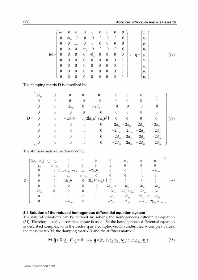
The mass matrix M and coordinate vector q are described by:
www.intechopen.com
Advances in Vibration Analysis Research
280
⎟⎟⎟⎟⎟⎟⎟⎟⎟⎟⎟⎟⎟
⎠
⎞
⎜⎜⎜⎜⎜⎜⎜⎜⎜⎜⎜⎜⎜
⎝
⎛
Θ=
000000000
000000000
000000000
000000000
00000000
00000000
00000000
00000000
00000000
sx
w
s
w
s
m
m
m
m
M ;
⎟⎟⎟⎟⎟⎟⎟⎟⎟⎟⎟⎟⎟
⎠
⎞
⎜⎜⎜⎜⎜⎜⎜⎜⎜⎜⎜⎜⎜
⎝
⎛
=
b
v
b
v
y
y
z
z
y
y
z
z
s
w
s
w
s
ϕq (35)
The damping matrix D is described by:
( )
⎟⎟⎟⎟⎟⎟⎟⎟⎟⎟⎟⎟⎟⎟
⎠
⎞
⎜⎜⎜⎜⎜⎜⎜⎜⎜⎜⎜⎜⎜⎜
⎝
⎛
−−−−
−−−−
+−
−
=
yyyyyzyz
yyyyyzyz
zyzyzzzz
zyzyzzzz
2
fz
2
fyfy
fyfy
fz
222200000
222200000
222200000
222200000
000020200
000000000
000020200
000000000
000000002
dddd
dddd
dddd
dddd
bdhdhd
hdd
d
D (36)
The stiffness matrix C is described by:
( )
⎟⎟⎟⎟⎟⎟⎟⎟⎟⎟⎟⎟⎟⎟
⎠
⎞
⎜⎜⎜⎜⎜⎜⎜⎜⎜⎜⎜⎜⎜⎜
⎝
⎛
+−−−−+−−
−+−−−−+−
+−−−
−−−+−−
−−+
=
)(222200200
22220000
22)(2200002
22220000
000020200
000000
20002)(200
000000
0020000)(2
byyyyyyzyzby
yyyyyzyz
zyzybzzzzzbz
zyzyzzzz
2
fz
2
fyfy
mm
byfymmbyfy
mm
bzmmbzfz
cccccc
cccccc
cccccc
cccccc
bchchc
cccc
chccccc
cccc
ccccc
C
(37)
3.4 Solution of the reduced homogenous differential equation system
The natural vibrations can be derived by solving the homogeneous differential equation (34). Therefore usually a complex ansatz is used. So the homogeneous differential equation is described complex, with the vector q as a complex vector (underlined = complex value), the mass matrix M, the damping matrix D and the stiffness matrix C.
0qCqDqM =⋅+⋅+⋅ $$$ with: Tyyzzyyzz );;;;;;;;(
bvbvswsws ϕ=q (38)
www.intechopen.com

A Plane Vibration Model for Natural Vibration Analysis of Soft Mounted Electrical Machines
281
The complex ansatz – with the complex eigenvalue λ and the complex eigenvectors hq
–
te ⋅⋅= λqq ˆ with: Tyyzzyyzz )ˆ;ˆ;ˆ;ˆ;ˆ;ˆ;ˆ;ˆ;ˆ(ˆ
bvbvswswsϕ=q (39)
leads to the eigenvalue equation:
0qMDC =⋅⋅+⋅+ ˆ][ 2λλ (40)
To get the complex eigenvalues λ, it is necessary to solve the determination equation:
0]det[ 2 =⋅+⋅+ MDC λλ (41)
This leads to a characteristic polynomial of 12th grade:
012
0
n =⋅∑=
n
n
A λ (42)
With a numerical solution of this polynomial, n complex eigenvalues λn – with the real parts αn, which describe the decay of each natural vibration and the imaginary parts ωn, which describe the corresponding natural angular frequencies – can be calculated. The eigenvalues
occur mostly conjugated complex ( j: imaginary unit → 12 −=j ):
nnnωαλ ⋅±= j (43)
With the complex eigenvalues λn the complex eigenvectors n
q can be calculated. Therefore
the natural vibrations can be described by:
t
n
ek ⋅=
⋅⋅=∑ n
12
1nn
ˆ λqq (44)
The factors kn can be used, to adapt the natural vibrations to the starting conditions. Using the calculated real part αn and the imaginary part ωn of each complex eigenvalue λn the modal damping Dn of each natural vibration mode can be derived (Kellenberger, 1987).
2n
2n
nn ωα
α+
−=D (45)
3.5 Stability of the vibration system If the oil film stiffness matrix Cv of the sleeve bearings is non symmetric (czy ≠ cyz) – for e.g. sleeve bearings with cylindrical shell the cross-coupling coefficients of the stiffness matrix are mostly unequal (czy ≠ cyz ) – also the system stiffness matrix C (37) gets non symmetric. This may lead to instabilities of the vibration system (Gasch et al., 2002), which occur if the real part of one or more complex eigenvalues gets positive, leading to negative modal damping values (45). The oil film stiffness and damping coefficients are a function of the rotary angular frequency Ω of the rotor.
)(;)( ijijijij ddcc == with i, j = z, y (46)
www.intechopen.com

Advances in Vibration Analysis Research
282
To find the limit of stability of the vibration system, the rotary angular frequency Ω has to be increased, until the real part of one or more complex eigenvalues becomes zero. Then the
limit of stability is reached at the rotary angular frequency Ω = Ω limit. At the limit of stability
the natural angular frequency of the critical mode becomes ωlimit and no damping exists
(αlimit = 0). So the critical complex eigenvalue at the limit of stability becomes:
limitlimitωλ ⋅±= j with 0limit =α (47)
With this complex eigenvalue the complex eigenvector can be calculated. So the undamped natural vibration at the limit of stability can be described by:
tjtj ekek ⋅−−−⋅++ ⋅⋅+⋅⋅= limitlimit
limitlimitlimitlimitlimit
ˆˆ ωω qqq (48)
At the limit of stability, that means at the rotary angular frequency of Ωlimit, which
represents the rotor speed nlimit (= Ω limit/2π), the undamped mode (with αlimit = 0) oscillates
with the natural angular frequency of ω limit, as a self exciting vibration.
4. Example
In this chapter the natural frequencies of a 2-pole induction motor (Fig. 1), mounted on a rigid foundation and also mounted on a soft steel frame foundation, is analyzed.
4.1 Data of motor, sleeve bearing and foundation
The machine data, sleeve bearing data and foundation data are shown in Table 1. First the stiffness data of the foundation are chosen arbitrarily. The damping ratio Df of the steel frame foundation is assumed to be 0.02, which is common for a welded steel frame. Machine data Sleeve bearing data
Rated power PN = 2000 kW Type of bearing Side flange bearing
Number of pole pairs p = 1 Bearing shell Cylindrical
Rated voltage UN = 6000 V Lubricant viscosity grade ISO VG 32
Rated frequency fN = 50 Hz Nominal bore diameter db = 110 mm
Rated torque MN = 6.4 kNm Bearing width bb = 81.4 mm
Rated speed nN = 2990 r/min Ambient temperature Tamb = 25°C
Mass of the stator ms = 7200 kg Lubricant supply temp. Tin = 40°C
Mass of the rotor mw = 1900 kg
Moment of inertia of the stator Θsx = 1550 kgm2
Mean relative bearing clearance (DIN 31698)
Ψm = 1.6 ‰
Height of the centre of gravity h = 560 mm
Distance between feet 2b = 1060 mm Foundation data
Rotor stiffness c = 155.7 kN/mmVertical foundation stiffness at each motor side
cfz = 133 kN/mm
Magnetic spring constant cm = 7.15 kN/mmHorizontal foundation stiffness at each motor side
cfy = 100 kN/mm
Vertical stiffness of bearing house and end shield
cbz = 570 kN/mm
Horizontal stiffness of bearing house and end shield
cby = 480 kN/mm
Damping ratio of the steel frame foundation
Df = 0.02
Table 1. Data of induction motor, sleeve bearings and foundation
www.intechopen.com

A Plane Vibration Model for Natural Vibration Analysis of Soft Mounted Electrical Machines
283
4.2 Oil film stiffness and damping coefficients
The oil film stiffness and damping coefficients of the sleeve bearings are calculated for each rotor speed in steady state operation, using the program SBCALC from RENK AG.
Fig. 6. Oil film stiffness and damping coefficients for different rotor speeds
4.3 Used FE-Program
To calculate the natural vibrations and to picture the mode shapes the finite element
program MADYN is used. A simplified finite element model is used (Fig. 7), which is based
on the model in Fig. 2. The degrees of freedom of the nodes are chosen in such a way, that
only movements in the transversal plane (y-z plane) occur.
Finite beam elements for
the shaft, without mass
Rotor mass mw
Stator
mass ms
Rigid beam
Rigid beam
Foundation spring
and damper
Foundation
spring and
damper
Sleeve bearing
Sleeve bearing
Spring for sleeve bearing and
and shield stiffness
Spring for sleeve
bearing and
and shield
stiffness
Ω Direction
of rotation
Rotor mass mw
Stator
mass ms
Rigid beam, connecting
stator mass to sleeve
bearing nodes
Rigid beam, connecting
stator mass to machine
feet nodes
Centre line
of the rotor
shaft Magnetic
spring
Detail: Rotor and stator
W
S
V, B
V, B
W, S
S: Centre of the stator
W: Centre of the rotor shaft
V: Centre of the shaft journal
B: Centre of the bearing housing
z
yx
Finite beam elements for
the shaft, without mass
Rotor mass mw
Stator
mass ms
Rigid beam
Rigid beam
Foundation spring
and damper
Foundation
spring and
damper
Sleeve bearing
Sleeve bearing
Spring for sleeve bearing and
and shield stiffness
Spring for sleeve
bearing and
and shield
stiffness
Ω Direction
of rotation
Rotor mass mw
Stator
mass ms
Rigid beam, connecting
stator mass to sleeve
bearing nodes
Rigid beam, connecting
stator mass to machine
feet nodes
Centre line
of the rotor
shaft Magnetic
spring
Detail: Rotor and stator
W
S
V, B
V, B
W, S
S: Centre of the stator
W: Centre of the rotor shaft
V: Centre of the shaft journal
B: Centre of the bearing housing
Finite beam elements for
the shaft, without mass
Rotor mass mw
Stator
mass ms
Rigid beam
Rigid beam
Foundation spring
and damper
Foundation
spring and
damper
Sleeve bearing
Sleeve bearing
Spring for sleeve bearing and
and shield stiffness
Spring for sleeve
bearing and
and shield
stiffness
Ω Direction
of rotation
Ω Direction
of rotation
Rotor mass mw
Stator
mass ms
Rigid beam, connecting
stator mass to sleeve
bearing nodes
Rigid beam, connecting
stator mass to machine
feet nodes
Centre line
of the rotor
shaft Magnetic
spring
Detail: Rotor and stator
W
S
V, B
V, B
W, S
S: Centre of the stator
W: Centre of the rotor shaft
V: Centre of the shaft journal
B: Centre of the bearing housing
z
yx
Fig. 7. Finite element model
Additionally the analytical formulas from chapter 3 could be validated with this finite
element model, by comparing the calculated eigenvalues, calculated by the analytical
formulas – which were solved by using the mathematic program MATHCAD – with the
eigenvalues, calculated with the finite element program MADYN.
www.intechopen.com

Advances in Vibration Analysis Research
284
4.4 Natural vibrations; motor mounted on a rigid foundation
Before the natural vibrations of the motor, mounted on the soft steel frame foundation, are analyzed the natural vibrations of the motor, mounted on a rigid foundation are calculated.
Therefore the foundation stiffness values are assumed to be infinite high (cfz = cyz → ∞ ).
4.4.1 Natural vibrations at rated speed
First the natural vibrations at rated speed are calculated. The mode shapes are pictured in Fig. 8. In the 1st mode the rotor mass – shaft centre point W - moves on an elliptical orbit, which is run through forwards. The semi-major axis of the orbit is about 34° shifted out of the horizontal axis. The orbit of rotor mass is larger than the orbits of the shaft journals. The orbits of the shaft journals – shaft journal points V – have the same orientation as the orbit of the rotor mass and are also run through forwards. The orbits of the bearing housing points B are much smaller than the orbits of the shaft journal points V, but are also run through forwards. Their semi-major axes are about 28° shifted out of the horizontal axis. Because of the infinite stiffness of the foundation no movement of the stator mass occurs. In the 2nd mode the semi-major axes of all orbits have the nearly the same orientation, shifted about 8° out of the horizontal axis. All orbits are run through forwards. In this mode the largest orbits are the orbits of the shaft journal points V. In the 3rd mode the semi-major axes of the
1th mode 2nd mode
3rd mode
ΩΩ
W
V
B
S
V
B W
B
S
V
B
V
W
B
V
S
BV
Ω
z
yx
z
yx
z
yx
z
yx
z
yx
z
yx
1th mode 2nd mode
3rd mode
ΩΩ
W
V
B
S
V
B W
B
S
V
B
V
W
B
V
S
BV
Ω
1th mode 2nd mode
3rd mode
ΩΩΩΩ
W
V
B
S
V
B W
B
S
V
B
V
W
B
V
S
BV
ΩΩ
z
yx
z
yx
z
yx
z
yx
z
yx
z
yx
Fig. 8. Mode shapes, motor mounted on a rigid foundation, operating at rated speed (nN = 2990 r/min)
www.intechopen.com

A Plane Vibration Model for Natural Vibration Analysis of Soft Mounted Electrical Machines
285
shaft centre point W and of the shaft journal points V are shifted about 15° out of the vertical
axis. The semi-major axes of the bearing housing points B are shifted about 20° out of the
vertical axis. All orbits are run through backwards. In this mode the orbit of the shaft centre
point W is much larger than the orbits of the shaft journal points V and the orbits of the
bearing housing points B, which are nearly equal to each other. This leads to a strong
bending of the rotor shaft with only small orbits in the sleeve bearings.
The natural frequencies and the modal damping values are shown in Table 2. Because of the
assumption of an infinite high foundation stiffness (cfz = cyz → ∞) only three natural
vibrations occur with three natural frequencies f1, f2, f3 and three modal damping values D1,
D2,D3. The modal damping values are here described in percentage.
Modes n
Natural frequency fn [Hz]
Modal dampingDn[%]
1 33.15 5.31
2 34.62 68.24
3 41.17 3.82
Table 2. Natural frequencies and modal damping, motor mounted on a rigid foundation, operating at rated speed (nN = 2990 r/min)
4.4.2 Critical speed map
In this chapter the natural frequencies and the modal damping for different rotor speeds are
calculated and a critical speed map is derived (Fig. 9).
Fig. 9 shows how the natural frequencies fn and the modal damping values Dn change with
the rotor speed nr, caused by the changing of the oil film stiffness and damping coefficients.
Where the rotary frequency (Ω/2π) meets the natural frequencies critical speeds regarding
the 1x excitation may occur if the modal damping value is low at this rotor speed. Usually, if
the modal damping value Dn is higher than 20% no critical resonance vibrations are
expected and the rotor speed is usually not assumed to be a critical speed. Here two critical
speeds have to be passed to reach the operating speed. The 1st critical speed occurs at about
a rotor speed of 2070 r/min with a modal damping value of about 15%. The 2nd critical
speed occurs at a rotor speed of 2475 r/min with a modal damping value of about 3.5%. Fig.
9 shows that a separation margin larger than 15% for the critical speeds to the operating
speed (2990 r/min) is given, which is required in many standards and specifications. Fig. 9
shows additionally that limit of stability is reached at a rotor speed of about 3900 r/min.
Here the modal damping of mode 1 gets zero.
4.4.3 Stiffness variation map regarding the electromagnetic stiffness
In this chapter the influence of the electromagnetic stiffness between the rotor and the stator
on the natural frequencies is analyzed. Therefore the magnetic spring constant cm, which
describes the electromagnetic stiffness between rotor and stator, is variegated by a factor kcm,
called magnetic stiffness factor. The rated magnetic spring constant is cm,rated = 7.15 kN/mm
(Table 1). The magnetic stiffness factor kcm is variegated in the range of 0…2 and the
influence on the natural frequencies and modal damping values are calculated for operation
at rated speed (Fig. 10).
www.intechopen.com

Advances in Vibration Analysis Research
286
-10
-5
0
5
10
15
20
25
30
35
40
45
50
55
60
65
70
75
80
600 900 1200 1500 1800 2100 2400 2700 3000 3300 3600 3900 4200 4500 4800
Rotor speed nr [r/min]
0
5
10
15
20
25
30
35
40
45
50
55
60
600 900 1200 1500 1800 2100 2400 2700 3000 3300 3600 3900 4200 4500 4800
Nat
ura
l fr
equ
ency f
n[H
z]M
od
al d
amp
ing D
n[%
]
Mode 1
Mode 2
Mode 3
Mode 1
Mode 2
Mode 3
Note: The numbering of the modes is related
to the operation at rated speed (2990 r/min)
π2/Ω
Rotor speed nr [r/min]
Fig. 9. Critical speed map, motor mounted on a rigid foundation
Magnetic spring constant: ratedm,cmm ckc ⋅= (49)
Fig. 10 shows that mode 1 and mode 3 are clearly influenced by the magnetic spring
constant. Their natural frequencies and modal damping values change with the magnetic
stiffness factor, whereas mode 2 is hardly influenced by the magnetic spring value. The
reason is that the orbits of rotor mass are larger than the orbits of the shaft journals for mode
1 and mode 3 (Fig. 8), contrarily to mode 2, where the orbits of the shaft journals are larger.
Therefore the influence of the magnetic spring constant, which acts at the rotor mass, is
higher for mode 1 and mode 3.
www.intechopen.com

A Plane Vibration Model for Natural Vibration Analysis of Soft Mounted Electrical Machines
287
67
68
69
20
22
24
26
28
30
32
34
36
38
40
42
44
0 0,2 0,4 0,6 0,8 1 1,2 1,4 1,6 1,8 2
Nat
ura
l fr
equ
ency f
n[H
z]
Mode 1
Mode 2
Mode 3
Note: The numbering of the modes is related
to the magnetic stiffness factor kcm = 1
Magnetic stiffness factor kcm [-]
Modal
dam
pin
g D
n[%
]
Mode 2
0
1
2
3
4
5
6
0 0,2 0,4 0,6 0,8 1 1,2 1,4 1,6 1,8 2
Mode 1
Mode 3
Magnetic stiffness factor kcm [-]
≈67
68
69
20
22
24
26
28
30
32
34
36
38
40
42
44
0 0,2 0,4 0,6 0,8 1 1,2 1,4 1,6 1,8 2
Nat
ura
l fr
equ
ency f
n[H
z]
Mode 1
Mode 2
Mode 3
Note: The numbering of the modes is related
to the magnetic stiffness factor kcm = 1
Magnetic stiffness factor kcm [-]
Modal
dam
pin
g D
n[%
]
Mode 2
0
1
2
3
4
5
6
0 0,2 0,4 0,6 0,8 1 1,2 1,4 1,6 1,8 2
Mode 1
Mode 3
Magnetic stiffness factor kcm [-]
0
1
2
3
4
5
6
0 0,2 0,4 0,6 0,8 1 1,2 1,4 1,6 1,8 2
Mode 1
Mode 3
Magnetic stiffness factor kcm [-]
≈
Fig. 10. Stiffness variation map regarding the electromagnetic stiffness, motor mounted on a rigid foundation, operating at rated speed (nN = 2990 r/min)
4.5 Natural vibrations; motor mounted on a soft steel frame foundation After the natural vibrations of the rigid mounted motor are analyzed, the natural vibrations of the motor, mounted on a soft steel frame foundation, are now investigated. The foundation data are described in Table 1.
4.5.1 Natural vibrations at rated speed Again, the natural vibrations at rated speed are calculated first. The natural frequencies are calculated once without considering of the foundation damping (Df = 0) and once with considering of the foundation damping (Df = 0.02). The mode shapes without considering foundation damping are pictured in Fig. 11, which can be assumed to be equal to the mode shapes with considering foundation damping. The first two modes are nearly rigid body modes of the soft mounted machine. Rotor and stator are nearly acting like a one-mass system. The orbits of the rotor and of the stator are nearly straight lines. In the 1st mode the rotor mass and the stator mass oscillate in phase to each other nearly in horizontal direction, while stator mass makes a lateral buckling at the x-axis, in the same direction as its horizontal movement. In the 2nd mode the rotor mass and the stator mass also oscillate in phase to each other, but in vertical direction. Nearly no buckling of
www.intechopen.com

Advances in Vibration Analysis Research
288
Ω
W
B
S
V
B
V
z
yx
z
yx
ΩW
B
S
V
BV
1th mode 2nd mode
3rd mode 4th mode
5th mode 6th mode
Ω
Ω
Ω
W B
SV
B
V
W
B
SV
B
V
W
B
S
V
B
V
z
yx
z
yx
z
yx
z
yx
z
yx
z
yx
Ω
W
B
S
VB
V
z
yx
z
yx
z
yx
z
yx
ΩΩ
W
B
S
V
B
V
z
yx
z
yx
ΩΩW
B
S
V
BV
1th mode 2nd mode
3rd mode 4th mode
5th mode 6th mode
ΩΩ
ΩΩ
ΩΩ
W B
SV
B
V
W
B
SV
B
V
W
B
S
V
B
V
z
yx
z
yx
z
yx
z
yx
z
yx
z
yx
ΩΩ
W
B
S
VB
V
z
yx
z
yx
z
yx
z
yx
Fig. 11. Mode shapes, motor mounted on a soft steel frame foundation (cfz = 133 kN/mm; cfy
= 100 kN/mm), without considering foundation damping (Df =0), operating at rated speed (nN = 2990 r/min)
the stator mass occurs. For the higher modes stator and rotor behave like a two- mass system and elliptical orbits of the rotor mass and stator mass occur. In the 3th mode the semi-major axes of orbits of the rotor mass, the bearing housings and the shaft journals are shifted about 12° out of the horizontal axis, whereas the semi-major axis of the orbit of the stator mass is only shifted 5° out of the horizontal axis. All orbits are run through forwards. The rotor mass and the stator mass oscillate out of phase to each other, as well as the shaft journals to the bearing housings. The largest orbits are the orbits of the shaft journals, compared to the other orbits. Because of the large relative orbits between the shaft journals and the bearing housings, the modal damping of this mode is very high, due to the oil film damping of the sleeve bearings. In the 4th mode the semi-major axis of the orbit of the rotor mass is shifted about 14° out of the horizontal axis. The same is valid for the shaft journals, whereas the semi-major axis of the
www.intechopen.com

A Plane Vibration Model for Natural Vibration Analysis of Soft Mounted Electrical Machines
289
stator orbit is shifted about 47° out of the horizontal axis. The semi-major axes of the orbits of the bearing housings are shifted about 62° out of the horizontal axis. All orbits are still run through forwards. In the 5th mode the semi-major axis of the orbit of the rotor mass is shifted about 12° out of the vertical axis. The other orbits lie nearly in vertical direction. The stator mass and the rotor mass oscillate out of phase to each other. The orbit of the stator mass and the orbits of the bearing housing are run through forwards, while the orbit of the rotor mass and the orbits of the shaft journals are run through backwards. In the 6th mode the semi-major axes of the orbits of the stator mass and of the bearing housings are shifted about 80° out of the vertical axis, while the semi-major axes of the orbits of the rotor mass and of the shaft journals are shifted about 45° out of the vertical axis. All orbits are run through backwards. Additionally the 6th mode shows a strong lateral buckling of the stator mass at the x-axis, which leads to large orbits at the motor feet. Contrarily to the 1st mode the lateral buckling of the stator mass is contrariwise to its horizontal movement, which means that if the stator mass moves to the right the lateral buckling is to the left. To consider the influence of the foundation damping on the natural vibrations, a simplified approach is used. Referring to (Gasch et al., 2002), the damping ratio Df of the foundation can be described by the damping coefficients dfq, stiffness coefficients cfq of the foundation and the stator mass ms, as a rough simplification.
sfqsffq /2 mcmDd ⋅⋅⋅= with: z,yq = (50)
The calculated natural frequencies and modal damping of each mode shape with and without considering foundation damping are shown in Table 3. It is shown that considering the foundation damping influences the natural frequencies only marginal, as expected. But the modal damping values of some modes are strongly influenced by the foundation damping. The modal damping values of the first two modes are strongly influenced by the foundation damping, because the modes are nearly rigid body modes of the motor on the foundation. Also the modal damping of the 6th mode is strongly influenced by the foundation damping, because large orbits of the motor feet occur in this mode shape, compared to the other orbits.
Without foundation damping (Df = 0) With foundation damping (Df = 0.02) Modes
n Natural frequency
fn [Hz] Modal damping
Dn [%] Natural frequency fn
[Hz] Modal damping
Dn [%]
1 16.05 -0.11 16.05 0.95
2 25.35 0.51 25.33 1.84
3 35.22 65.75 35.23 65.72
4 37.72 6.97 37.67 7.36
5 48.50 3.39 48.54 4.24
6 52.63 1.0 52.61 4.17
Table 3. Natural frequencies and modal damping, motor mounted on a soft steel frame foundation (cfz = 133 kN/mm; cfy = 100 kN/mm) with and without considering foundation damping (Df = 0.02 and Df = 0), operating at rated speed (nN = 2990 r/min)
4.5.2 Critical speed map
Again, a critical speed map is derived to show the influence of the rotor speed on the natural frequencies and the modal damping and to derive the critical speeds (Fig. 12).
www.intechopen.com

Advances in Vibration Analysis Research
290
-2
-1
0
1
2
3
4
5
6
7
8
9
10
11
12
13
14
15
600 900 1200 1500 1800 2100 2400 2700 3000 3300 3600 3900 4200 4500 4800
60
65
70
75
0
5
10
15
20
25
30
35
40
45
50
55
60
600 900 1200 1500 1800 2100 2400 2700 3000 3300 3600 3900 4200 4500 4800
Rotor speed nr [r/min]
Mode 1
Mode 2
Mode 3
Mode 1
Mode 3
Mode 6
Mode 4
Mode 5
Mode 6
≈
Mode 2
Mode 5
Mode 4
Note: The numbering of the modes is related
to the operation at rated speed (2990 r/min)
π2/Ω
Nat
ura
l fr
equ
ency f
n[H
z]M
odal
dam
pin
g D
n[%
]
Rotor speed nr [r/min]
Fig. 12. Critical speed map, motor mounted on a soft steel frame foundation (cfz = 133 kN/mm; cfy = 100 kN/mm; Df =0.02)
Critical speed Critical speed [r/min] Modal damping Dn [%]
1 950 1.6
2 1540 2.3
3 2340 12.2
4 2900 4.3
5 3160 4.2
Table 4. Critical speeds, motor mounted on a soft steel frame foundation (cfz = 133 kN/mm; cfy = 100 kN/mm; Df =0.02)
Fig. 12 shows that the limit of stability is here reached at about 4650 r/min, because the
modal damping of mode 4 gets zero at this rotor speed. For the rigid foundation the limit of
stability is already reached at a rotor speed of about 3900 r/min. But contrarily to the rigid
mounted motor here four critical speeds have to be passed before the operating speed (2990
r/min) is reached. Additionally a 5th critical speed is close above the operating speed. The
critical speeds and the modal damping in the critical speeds are shown in Table 4.
www.intechopen.com

A Plane Vibration Model for Natural Vibration Analysis of Soft Mounted Electrical Machines
291
Table 4 shows that two critical speeds (4th and 5th) with low modal damping values are very close to the operating speed (2990 r/min), having less than 5% separation margin to the operating speed. Therefore resonance vibrations problems may occur. The conclusion is that the arbitrarily chosen foundation stiffness values are not suitable for that motor with a operation speed of 2990 r/min. To find adequate foundation stiffness values, a stiffness variation of the foundation is deduced and a stiffness variation map is created (chapter 4.5.4). But preliminarily the influence of the electromagnetic stiffness on the natural frequencies and modal damping values is investigated for the soft mounted motor.
4.5.3 Stiffness variation map regarding the electromagnetic stiffness
In this chapter the influence of the electromagnetic stiffness on the natural frequencies and the modal damping values at rated speed is analyzed again, but now for the soft mounted motor. Again the magnetic stiffness factor kcm is variegated in a range of 0….2 and the influence on the natural frequencies and the modal damping values is analyzed. Fig. 13
15
17
19
21
23
25
27
29
31
33
35
37
39
41
43
45
47
49
51
53
55
0 0,2 0,4 0,6 0,8 1 1,2 1,4 1,6 1,8 2
Magnetic stiffness factor kcm [-]
Mode 1
Mode 2
Mode 3Mode 4
Mode 5
Mode 6
Note: The numbering of the modes is related
to the magnetic stiffness factor kcm = 1
Nat
ura
l fr
equ
ency f
n[H
z]
0
1
2
3
4
5
6
7
8
0 0,2 0,4 0,6 0,8 1 1,2 1,4 1,6 1,8 2
Mode 1
Mode 3
Mode 6
≈
Mode 2
Mode 4
Mode 5
Mo
dal
dam
pin
g D
n[%
]
Magnetic stiffness factor kcm [-]
65
66
67
Fig. 13. Stiffness variation map regarding the electromagnetic stiffness, motor mounted on a soft steel frame foundation (cfz = 133 kN/mm; cfy = 100 kN/mm; Df = 0.02), operating at rated speed (nN = 2990 r/min)
www.intechopen.com

Advances in Vibration Analysis Research
292
shows that mainly the natural frequencies of the 4th mode and the 5th mode are influenced by the magnetic spring constant. The natural frequencies of the other modes are hardly influenced by the magnetic spring constant. The reason is that for the 4th mode and the 5th mode the relative orbits between the rotor mass and the stator mass are large, compared to the other orbits. Large orbits of the rotor mass and of the stator mass occur for these two modes and both masses – the rotor mass and the stator mass – vibrate out of phase to each other (Fig. 11), which lead to large relative orbits between these two masses. Therefore, the electromagnetic interaction between these two masses is high and therefore a significant influence of the magnetic spring constant on the natural vibrations occurs for these two modes. In the 1st and 2nd mode the motor is acting like a one-mass system (Fig. 11) and nearly no relative movements between rotor mass and stator mass occur. Therefore the electromagnetic coupling between rotor and stator has nearly no influence on the natural frequencies of the first two modes. The 3th mode is mainly dominated by large relative orbits between the shaft journals and the bearing housings – compared to the other orbits – leading to high modal damping. A relative movement between the rotor mass and the stator occurs, but is not sufficient enough for a clear influence of the electromagnetic coupling. The 6th mode is mainly dominated by large orbits of the motor feet, compared to the other orbits. Again the relative movement of the stator and rotor is not sufficient enough that the electromagnetic coupling influences the natural frequency of this mode clearly. The modal damping values of all modes are only marginally influenced by the magnetic spring constant, only a small influence on the modal damping of the 4th mode is obvious.
4.5.4 Stiffness variation map regarding the foundation stiffness
The foundation stiffness values cfz and cyz are changed by multiplying the rated stiffness values cfz,rated and cfy,rated from Table 1 with a factor, called foundation stiffness factor kcf.
Vertical foundation stiffness: ratedfz,cffz ckc ⋅= (51)
Horizontal foundation stiffness: ratedfy,cffy ckc ⋅= (52)
Therefore the vertical foundation stiffness cfz and the horizontal foundation stiffness cfy are
here changed in equal measure by the foundation stiffness factor kcf. The influence of the
foundation stiffness at rated speed on the natural frequencies and on the modal damping is
shown in Fig. 14.
It is shown that for a separation margin of 15% between the natural frequencies and the
rotary frequency Ω/2π the foundation stiffness factor kcf has to be in a range of 2.5…3.0. If
the foundation stiffness factor is smaller than 2.5 the natural frequency of the 5th mode gets
into the separation margin. If the foundation stiffness factor is bigger than 3.0 the natural
frequency of the 4th mode gets into the separation margin. Both modes – 4th mode and 5th
mode – have a modal damping less than 10% in the whole range of the considered
foundation stiffness factor (kcf = 0.5…4). Because of the low modal damping values of these
two modes, the operation close to the natural frequencies of these both modes suppose to be
critical. Therefore the first arbitrarily chosen foundation stiffness values (cfz,rated = 133
kN/mm; cfy,rated = 100 kN/mm) have to be increased by a factor of kcf = 2.5…3.0. With the
increased foundation stiffness values the foundation can still be indicated as a soft
foundation, because the natural frequencies of the 1st mode and the 2nd mode – the mode
www.intechopen.com

A Plane Vibration Model for Natural Vibration Analysis of Soft Mounted Electrical Machines
293
shapes are still the same as in Fig. 11 – are still low, lying in a range between 24 Hz and 26
Hz for the 1st mode and between 33 Hz and 35 Hz for the 2nd mode.
60
65
70
75
0
1
2
3
4
5
6
7
8
9
10
0,5 1 1,5 2 2,5 3 3,5 4
0
5
10
15
20
25
30
35
40
45
50
55
60
65
70
75
80
85
90
95
100
105
110
0,5 1 1,5 2 2,5 3 3,5 4
Foundation stiffness factor kcf [-]
Mode 1
Mode 2Mode 3
Mode 1
Mode 3
Mode 6
Mode 4
Mode 5
Mode 6
≈
Mode 2
Mode 4
Mode 5
Note: The numbering of the modes is related
to the foundation stiffness factor kcf = 1
Range of the foundation stiffness
factor kcf for the boundary condition: ⎩⎨⎧
⋅≥⋅≤
ππ
2/15.1
2/85.0n
f
Nat
ura
l fr
equ
ency f
n[H
z]M
odal
dam
pin
g D
n[%
]
π2/Ω
Foundation stiffness factor kcf [-]
Separation margin of ±15%
to the rotary frequency Ω/2π
60
65
70
75
0
1
2
3
4
5
6
7
8
9
10
0,5 1 1,5 2 2,5 3 3,5 4
0
5
10
15
20
25
30
35
40
45
50
55
60
65
70
75
80
85
90
95
100
105
110
0,5 1 1,5 2 2,5 3 3,5 4
Foundation stiffness factor kcf [-]
Mode 1
Mode 2Mode 3
Mode 1
Mode 3
Mode 6
Mode 4
Mode 5
Mode 6
≈
Mode 2
Mode 4
Mode 5
Note: The numbering of the modes is related
to the foundation stiffness factor kcf = 1
Range of the foundation stiffness
factor kcf for the boundary condition: ⎩⎨⎧
⋅≥⋅≤
ππ
2/15.1
2/85.0n
f
Nat
ura
l fr
equ
ency f
n[H
z]M
odal
dam
pin
g D
n[%
]
π2/Ω
Foundation stiffness factor kcf [-]
Separation margin of ±15%
to the rotary frequency Ω/2π
Fig. 14. Stiffness variation map regarding the foundation stiffness, motor mounted on a soft steel frame foundation, operating at rated speed (nN = 2990 r/min)
5. Conclusion
The aim of this paper is to show a simplified plane vibration model, describing the natural vibrations in the transversal plane of soft mounted electrical machines, with flexible shafts and sleeve bearings. Based on the vibration model, the mathematical correlations between the rotor dynamics and the stator movement, the sleeve bearings, the electromagnetic and the foundation, are derived. For visualization, the natural vibrations of a soft mounted 2-pole induction motor are analyzed exemplary, for a rigid foundation and for a soft steel frame foundation. Additionally the influence of the electromagnetic interaction between rotor and stator on the natural vibrations is analyzed. Finally, the aim is not to replace a
www.intechopen.com

Advances in Vibration Analysis Research
294
detailed three-dimensional finite-element calculation by a simplified plane multibody model, but to show the mathematical correlations based on a simplified model.
6. References
Arkkio, A.; Antila, M.; Pokki, K.; Simon, A., Lantto, E. (2000). Electromagnetic force on a whirling cage rotor. Proceedings of Electr. Power Appl., pp. 353-360, Vol. 147, No. 5
Belmans, R.; Vandenput, A.; Geysen, W. (1987). Calculation of the flux density and the unbalanced magnetic pull in two pole induction machines, pp. 151-161, Arch. Elektrotech, Volume 70
Bonello, P.; Brennan, M.J. (2001). Modelling the dynamic behaviour of a supercritcial rotor on a flexible foundation using the mechanical impedance technique, pp. 445-466, Journal of sound and vibration, Volume 239, Issue 3
Gasch, R.; Nordmann, R. ; Pfützner, H. (2002). Rotordynamik, Springer-Verlag, ISBN 3-540-41240-9, Berlin-Heidelberg
Gasch, R.; Maurer, J.; Sarfeld W. (1984). The influence of the elastic half space on stability and unbalance of a simple rotor-bearing foundation system, Proceedings of Conference Vibration in Rotating Machinery, pp. 1-11, C300/84, IMechE, Edinburgh
Glienicke, J. (1966). Feder- und Dämpfungskonstanten von Gleitlagern für Turbomaschinen und deren Einfluss auf das Schwingungsverhalten eines einfachen Rotors, Dissertation, Technische Hochschule Karlsruhe, Germany
Holopainen, T. P. (2004) Electromechanical interaction in rotor dynamics of cage induction motors, VTT Technical Research Centre of Finland, Ph.D. Thesis, Helsinki University of Technology, Finland
Kellenberger, W. (1987) Elastisches Wuchten, Springer-Verlag, ISBN 978-3540171232, Berlin-Heidelberg
Lund, J.; Thomsen, K. (1987). Review of the Concept of Dynamic Coefficients for Fluid Film Journal Bearings, pp. 37-41, Journal of Tribology, Trans. ASME, Vol. 109, No. 1
Lund, J.; Thomsen, K. (1978). A calculation method and data for the dynamics of oil lubricated journal bearings in fluid film bearings and rotor bearings system design and optimization, pp. 1-28, Proceedings of Conference ASME Design and Engineering Conference, ASME , New York
Schuisky, W. (1972). Magnetic pull in electrical machines due to the eccentricity of the rotor, pp. 391-399, Electr. Res. Assoc. Trans. 295
Seinsch, H-O. (1992). Oberfelderscheinungen in Drehfeldmaschinen, Teubner-Verlag, ISBN 3-519-06137-6, Stuttgart
Tondl, A. (1965). Some problems of rotor dynamics, Chapman & Hall, London Vance, J.M.; Zeidan, F. J.; Murphy B. (2010). Machinery Vibration and Rotordynamics, John
Wiley and Sons, ISBN 978-0-471-46213-2, Inc. Hoboken, New Jersey Werner, U. (2010). Theoretical vibration analysis of soft mounted electrical machines
regarding rotor eccentricity based on a multibody model, pp. 43-66, Springer, Multibody System Dynamics, Volume 24, No. 1, Berlin/Heidelberg
Werner, U. (2008). A mathematical model for lateral rotor dynamic analysis of soft mounted asynchronous machines. ZAMM-Journal of Applied Mathematics and Mechanics, pp. 910-924, Volume 88, No. 11
Werner, U. (2006). Rotordynamische Analyse von Asynchronmaschinen mit magnetischen Unsymmetrien, Dissertation, Technical University of Darmstadt, Germany, Shaker-Verlag, ISBN 3-8322-5330-0, Aachen
www.intechopen.com

Advances in Vibration Analysis ResearchEdited by Dr. Farzad Ebrahimi
ISBN 978-953-307-209-8Hard cover, 456 pagesPublisher InTechPublished online 04, April, 2011Published in print edition April, 2011
InTech EuropeUniversity Campus STeP Ri Slavka Krautzeka 83/A 51000 Rijeka, Croatia Phone: +385 (51) 770 447 Fax: +385 (51) 686 166www.intechopen.com
InTech ChinaUnit 405, Office Block, Hotel Equatorial Shanghai No.65, Yan An Road (West), Shanghai, 200040, China
Phone: +86-21-62489820 Fax: +86-21-62489821
Vibrations are extremely important in all areas of human activities, for all sciences, technologies and industrialapplications. Sometimes these Vibrations are useful but other times they are undesirable. In any case,understanding and analysis of vibrations are crucial. This book reports on the state of the art research anddevelopment findings on this very broad matter through 22 original and innovative research studies exhibitingvarious investigation directions. The present book is a result of contributions of experts from internationalscientific community working in different aspects of vibration analysis. The text is addressed not only toresearchers, but also to professional engineers, students and other experts in a variety of disciplines, bothacademic and industrial seeking to gain a better understanding of what has been done in the field recently,and what kind of open problems are in this area.
How to referenceIn order to correctly reference this scholarly work, feel free to copy and paste the following:
Ulrich Werner (2011). A Plane Vibration Model for Natural Vibration Analysis of Soft Mounted ElectricalMachines, Advances in Vibration Analysis Research, Dr. Farzad Ebrahimi (Ed.), ISBN: 978-953-307-209-8,InTech, Available from: http://www.intechopen.com/books/advances-in-vibration-analysis-research/a-plane-vibration-model-for-natural-vibration-analysis-of-soft-mounted-electrical-machines

© 2011 The Author(s). Licensee IntechOpen. This chapter is distributedunder the terms of the Creative Commons Attribution-NonCommercial-ShareAlike-3.0 License, which permits use, distribution and reproduction fornon-commercial purposes, provided the original is properly cited andderivative works building on this content are distributed under the samelicense.