a pocket guide to motor starter selection & maintenance
TRANSCRIPT

A pocket guide to Motor Starter Selection & Maintenance
s

2
Contents: Page No.
1. Starter Details ------------------------------------------------------------- 3
a. Direct-on-line Starting
b. Star-delta Starting
2. Selection of Motor Starters ----------------------------------------- 10
a. Raja Motor Starters
a-1 Direct-On-Line Starters (upto 10 hp)
a-2 Star-Delta Starters-Handle Operated (upto 15 hp)
b Other Motor Starters
b-1 Direct-on-line Starters-20 hp & above
b-2 Star-delta Starters - Automatic
3. Wiring diagrams -------------------------------------------------------- 12
a. Direct-on-line Starter
b. Star-delta Starter
b-1 Handle Operated
b-2 Automatic
4. Installation & Maintenance guidelines -------------------------- 17
a. Installation
b. Maintenance
c. Dimensional Drawings
5. Trouble shooting ------------------------------------------------------- 23
6. Spares for RAJA starters ---------------------------------------------- 27
7. Siemens Contact Partners

1. Starter Details:
A motor Starter has two basic functions to perform;
1) Starting and stopping the motor.
2) Providing adequate protection to the motor and safeguarding it in the event of sustained overloads, single phasing, locked rotor conditions and undervoltage.
Siemens makes a wide variety and range of Starters suitable for various applications. However, for small general purpose motor feeders, we
normally come across;
a) Direct-on-line starting and
b) Star Delta starting
1.a Direct-On-Line Starting
General:The most economical and popular method of starting squirrel cage induction motors, is direct-on-line, where the starter is connected directly across the three phases of the supply. However, the starting current at the moment of switching direct-on-line can be as high
3
Fig. 1

as 6-8 times the rated current. Due to this reason, the Electricity Boards have laid down general regulations that direct-on-line starting of squirrel cage motors shall be allowed only for small motors-upto 5 or 7.5 H.P. This regulation is particularly enforced in rural areas.The Siemens direct-on-line starter (Ref. Fig. 2) consists of three functional components:1) The contactor which
is responsible for the switching function and low voltage protection.
2) The bimetal overload relay which is the sensing device that switches off the contactor when the motor gets overloaded or under single phasing.
3) Push buttons used for switching ‘ON’ and ‘OFF’
Contactor : The new DOL starter designed by Siemens for motors up to 10 HP is fitted with 3 TW02 type of contactor. This contactor is specially designed by Siemens considering the requirements of industry as well as agriculture.
4
Fig. 2 Direct On Line Starter

Considering the specific need of the agricultural pumpset applications, Siemens has designed a special wide band coil (200-400V). This coil can operate reliably even when there is wide voltage fluctuation.
The contact rating of this contactor is 20 A. This high contact rating has made RAJA starter the most suitable starter even for the starting of 7.5 HP submersible pumps.
Bimetal Overload Relay: The RAJA direct-on-line starter is fitted with the new 3UW50 type of relay. These relays are computer calibrated and therefore, are very accurate.
The main benefit of this bimetal relay is the built-in single phasing protection in addition to the overload protection.
Operation of D.O.L. starter: For starting, the ‘ON’ push button is pressed, which energizes the contactor coil, thus switching on the circuit.
When the ‘OFF’ push button is pressed, the contactor is de-energized, switching off the circuit.
The bimetal relay under normal functioning of motor, plays no active part in the starter. But under overload, single phasing or locked rotor conditions of motor, the bimetal relay cuts-off the supply to the contactor coil, tripping the circuit. The contactor itself provides the necessary ‘no-voltage’ protection in so far as it will drop out in the case of a supply failure, and for restarting on resumption of supply, the ‘ON’ push button will have to be pressed again.
1.b Star-Delta Starting:General:
For squirrel cage motors which cannot be started direct-on-line due to starting current limitations, the simplest alternative is star-delta starting.
In star-delta starting the motor is started in ‘star’ connection,
5

the connections being changed over to ‘delta’ when the motor has reached nearly rated speed. By connecting the motor in ‘star’ during the starting period, the impressed phase voltage is reduced to 0.58 of the voltage in ‘delta’ connection. The corresponding line current in ‘star’ is thus only one-third that in delta. For most motors started direct-on-line, the current at the moment of staring is about six to eight times its rated current and therefore by starting in ‘star’ the current is reduced to only about 2 to 2.5 times the rated current.
As both, the phase voltage and current are reduced during the starting period in ‘star’ connection, the torque is also reduced and is only one-third of that in ‘delta’. The starting torque produced by normal duty motors is about 150% of the rated torque and hence star-delta starting can be used only with drives where the load torque at the moment of starting is not more than 50% of the rated torque.
Fig. 3 gives a graphical representation of the star-delta phenomena. The motor
6
Fig. 3 - Star Delta Principle
Iy = Current in Y-connection
ID = Current in ∆ connection
Synchronous speed
Speed/rated speed
Cu
rren
t/ra
ted
op. c
urr
ent

is started in ‘star’ and once it has picked up speed, its connections are changed over to ‘delta’ However, the timing of the changeover is extremely important. To illustrate this, two changeover points ‘A’, ‘B’ have been shown to illustrate the effect of an early changeover. The shape of the delta curve is such that no appreciable limitation of the current is possible till the motor speed has reached at least 80% of its synchronous value.
Siemens manufactures two basic types of Star-delta starters:
1) Handle Operated Star-Delta Starter where the changeover of stator connections from ‘star’ to ‘delta’ is done manually through a switch.
2) Automatic Star-Delta Starter where the changeover of stator connections from ‘star’ to ‘delta’ is automatic after a preset time by the use of a timer.
For closer protection of the motor, particularly against single phasing, the overload relay in all Siemens Star-Delta Starters has been connected in the phase circuit, and hence should be set for 0.58 times the actual current drawn by the motor, as measured by an ammeter. In no case should be bimetal setting be more than 0.58 times the rated line current mentioned on the motor name plate.
Star-Delta Starter (Handle Operated):Siemens RAJA Handle Operated Star-Delta starter type 3LW42 consists of a star-delta switch, a contactor, an overload relay, “Reset” push button and a safety ‘ON’ push button. (Fig. 4)
This RAJA starter, too, is fitted with the new 3TW02 contactor and the new 3UW50 bimetal overload relay which are discussed in section 1.a above.
The 3LAO is a motor control switch capable of making and
7

breaking 6-8 times the rated current. A mechanical life of 50 lakh switching cycles is achieved by the use of a ‘form-fit’ design of parts. Special bearings are provided where parts of metal rub against plastic. These bearings show 200 times less wear than friction between metals.
The use of silver as contact material and short contact opening paths ensures a contact life of 10 lakh switching cycles.
This switch is used for the star-delta switching function.
Operation:
To start the motor, move the 3LAO switch handle from ‘O’ position to ‘star’ (Y) position with the right hand and press the ‘start’ - (I) push button with your left hand. The motor starts and when it has almost come to its rated speed (indicated when the motor hum reaches a steady pitch), turn the handle to ‘delta’ position, still taking care to keep the push button pressed.
8
Fig. 4 Star-Delta Starter (Handle Operated)
9
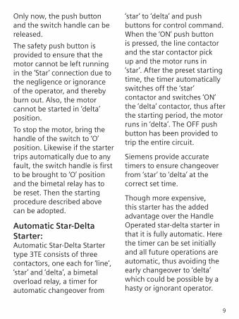
Only now, the push button and the switch handle can be released.
The safety push button is provided to ensure that the motor cannot be left running in the ‘Star’ connection due to the negligence or ignorance of the operator, and thereby burn out. Also, the motor cannot be started in ‘delta’ position.
To stop the motor, bring the handle of the switch to ‘O’ position. Likewise if the starter trips automatically due to any fault, the switch handle is first to be brought to ‘O’ position and the bimetal relay has to be reset. Then the starting procedure described above can be adopted.
Automatic Star-Delta Starter:Automatic Star-Delta Starter type 3TE consists of three contactors, one each for ‘line’, ‘star’ and ‘delta’, a bimetal overload relay, a timer for automatic changeover from
‘star’ to ‘delta’ and push buttons for control command. When the ‘ON’ push button is pressed, the line contactor and the star contactor pick up and the motor runs in ‘star’. After the preset starting time, the timer automatically switches off the ‘star’ contactor and switches ‘ON’ the ‘delta’ contactor, thus after the starting period, the motor runs in ‘delta’. The OFF push button has been provided to trip the entire circuit.
Siemens provide accurate timers to ensure changeover from ‘star’ to ‘delta’ at the correct set time.
Though more expensive, this starter has the added advantage over the Handle Operated star-delta starter in that it is fully automatic. Here the timer can be set initially and all future operations are automatic, thus avoiding the early changeover to ‘delta’ which could be possible by a hasty or ignorant operator.

a-2 RAJA Star-Delta Starters (Handle Operated)
Motor Rating Relay Back-up Copper Cable at 415 V Starter Type Range Fuse (mm2) Size 3ph, 50Hz HRC Incoming Outgoing kW HP from Supply to motor
3.7 5 3LW90-0A*72 4 - 6.3A 32 A 2.5 1.5
7.5 10 3LW42 90-0A*74 6.3 - 10 32 A 2.5 1.5
9.3 12.5 3LW42 90-0A*75 8 - 12.5 32 A 2.5 2.5
11 15 3LW42 90-0A*77 10 - 16 32 A 4.0 2.5
*Enter code for coil voltage. (“B” for 200-400V, “W” for 415V)
a. RAJA Motor Starters
a-1 RAJA Direct-on-Line Starters
Motor Rating Relay Back-up Cu at 415 V Starter Type Range Fuse Rating Cable 3ph, 50Hz (Recommended) (mm2)
kW HP HRC Rewirable Size
0.25 0.33 3TW42 90-1A*64 0.63 - 1 4 A 36 SWG 1
0.55 0.75 3TW42 90-1A*66 1 - 1.6 6 A 34 SWG 1
0.75 1 3TW42 90-1A*68 1.6 - 2.5 6 A 27 SWG 1
1.1 1.5 3TW42 90-1A*69 2 - 3.2 10 A 26 SWG 1
1.5 2 3TW42 90-1A*71 3.2 - 5 16 A 25 SWG 1
2.2 3 3TW42 90-1A*72 4 - 6.3 16 A 24 SWG 1.5
3.7 5 3TW42 90-1A*74 6.3 - 10 25 A 21 SWG 1.5
- - 3TW42 90-1A*75 8 - 12.5 25 A 19 SWG 1.5
5.5 7.5 3TW42 90-1A*77 10 - 16 32 A 18 SWG 2.5
7.5 10 3TW42 90-1A*78 12.5 - 20 32 A 18 SWG 4
2. Selection of Motor Starters
10

b-2 Higher Rated Automatic Star-Delta Starters (without birelay) Motor Rating Relay Recommended at 415 V 3ph, 50Hz Starter Type Range Back-up kW HP (Recommended) Fuse HRC 22 30 3TE04 94-2A## 3UA55 (16-25A) 50 A 30 40 3TE04 94-2A## 3UA55 (20-32A) 63 A 37 50 3TE04 95-2A## 3UA55 (32-40A) 80 A 45 60 3TE04 96-2A## 3UA58Z1 (32-50A) 100 A 55 75 3TE04 97-2A## 3UA58Z1 (40-57A) 100 A
## Enter code for coil voltage. (“RO” for 415V, “PO” for 230V)
a-3 Raja Star-Delta Starters (Automatic) Motor Rating Relay Recommended at 415 V 3ph, 50Hz Starter Type Range Back-up kW HP Fuse HRC 9.3 12.5 3TE02 90-0A*75 8 - 12.5 25 11 15 3TE02 90-0A*77 10 - 16 32 15 20 3TE02 90-0A*78 12.5 - 20 50 18.5 25 3TE02 90-0A*79 16 - 25 50
* Enter code for coil voltage, 50Hz. (“D” for 230-400V, “W” for 415V)
b. Other Starters
b-1 Direct-on-Line Starters - 20HP & above (without birelay) Motor Rating Relay Recommended at 415 V 3ph, 50Hz Starter Type Range Back-up kW HP (Recommended) Fuse HRC 15 20 3TW04 94-2A## 3UA55 (20-32A) 50 A 18.5 25 3TW04 95-2A## 3UA55 (25-36A) 63 A 22 30 3TW04 96-2A## 3UA58Z1 (32-50A) 80 A 30 40 3TW04 97-2A## 3UA58Z1 (40-57A) 100 A 37 50 3TW04 98-2A## 3UA58Z2 (57-70A) 125 A
55 75 3TW05 90-2A## 3UA5830 (85-105A) 160 A
## Enter code for coil voltage. (“RO” for 415V, “PO” for 230V)
11

12
3. Wiring Diagrams:
RAJA Direct-On-Line Starter
3TW42 90-1A
• Diagram shows connections made for contactor coils rated 200 - 400V (wide-band), 415V (320-455V), 50Hz.
• For coils rated between 220V and 250V 50Hz, disconnect the wire between L3-96 and connect the neutral of the supply system to the terminal 96 of the relay.

13
RAJA Direct-On-Line Starter (for Remote Operation)
3TW42 90-1A
• Diagram shows connections made for contactor coils rated 200 - 400V (wide-band), 415V (320-455V), 50Hz.
• For remote operation disconnect the wire between terminal 5/L3 on contactor and terminal 96 on the relay. Connect the remote ‘OFF’ S01 push button as shown. Connect remote ‘ON’ S11 push button parallel to S1 as shown.

14
RAJA Direct-On-Line Starter (for Single Phase connection)
3TW42 90-1A
• Wiring Diagram for Single-Phase Motors
Note : Connect 3/L2 to 2/T1 by cable of suitable size. (max 4 mm2)

15
RAJA Star-Delta Starter (Handle Operated)
3LW42 90-0A
• Diagram shows connections made for contactor coils rated 200 - 400V (wide-band), 415V (320-455V), 50Hz.
• For coils rated between 220V and 250V 50Hz, disconnect the wire between 1/L1-96 and connect the neutral of the supply system to the terminal 96 of the relay.
S1 = ON Push ButtonS0 = Reset Push ButtonQ1 = ContactorK1 = Bimetal Relay with
SPP FeatureS10 = 3LA0 switch
16
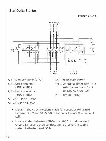
Star-Delta Starter
3TE02 90-0A
• Diagram shows connections made for contactor coils rated between 380V and 500V, 50Hz and for 230V-400V wide band coil.
• For coils rated between 220V and 250V, 50Hz. disconnect Q1.b-Q1.5/L3 and then connect the neutral of the supply system to the terminal Q1.b.
Q1 = Line Contactor (2NO)Q2 = Star Contactor
(1NO + 1NC)Q3 = Delta Contactor
(1NO + 1NC)S0 = OFF Push ButtonS1 = ON Push Button
S4 = Reset Push ButtonQ4 = Star Delta Timer with 1NO
instantaneous and 1NO delayed Aux. Contact
K1 = Bimetal Relay

17
4. Installation & Maintenance guidelinesA. Installation:
a) Use the suitable starter as per your requirements. (Refer section 2 - Selection of Motor Starters)
b) Use the appropriate cable sizes and back-up fuse for smooth operation of the starter. Terminal screws = M4, stripped length = 10 mm, max. = 4 mm2 copper
c) Mount the starter on vertical, rigid surface (maximum tilt permissible = ±15o with respect to the vertical plane)
d) Use of cable glands is recommended to avoid dust ingress.
e) Set the blue knob on the relay to ‘manual’ or ‘auto’ mode as appropriate.
f) Set the relay to actual motor current or as outlined in the operating instructions booklet.
g) Check the ‘on’/’off’ operation as outlined elsewhere in this brochure.
B. Maintenance
Caution ! Switch off the starter and disconnect the main supply by switching off the main switch before doing any maintenance.Follow the various maintenance tips given in the operating instruction booklet
Routine Inspection: Inspect terminals, contacts, arc chambers periodically - two months after installation and every six months thereafter. Routine inspections help to monitor the state of the contactor. These contribute to the reliability of the plant and minimize risk of breakdown during production hours.
Isolation for Maintenance: Switch off the contactor & upstream devices before inspecting the contactor as a safety precaution.
Terminals: Tighten terminals periodicallyConnections have a tendency to loosen with time -
particularly those of aluminium which is a soft material. The terminals should be tightened with a torque specified in the table.
Screws Tightening torque. N cm
M 3.0 40 - 55
M 3.5 80 - 100
M 4.0 80 - 100
Contact Condition: Tarnished/Blackened Contact : Tarnishing is normal for any silver item, it is due to the formation of silver oxide which is a good conductor of heat and electricity, hence tarnished contacts need not be replaced. Blackened or sooty contacts which are otherwise in a good condition need not be replaced. These contacts can be cleaned with CRC 2-26.Do not replace slightly pitted contact. Whether a contact is good or not depends on the volume of contact material which remains in it. Replace contacts when the contact tip has
become less than 40% of its original volume.
Do not employ carbon impression method to check healthiness of contacts. Do not use abrasives e.g. do not file contacts, do not use emery paper on contacts. Abrasives remove silver from the contact tip & drastically reduce the contact life.
Do not grease the contacts.
The contact condition should be inspected after a fault i.e. short circuit. If the contacts are slightly welded, separate them with a screw driver. Slight but separable welding does not affect the performance of the contactor, its acceptability is recognized by IS13947/IEC 947 specifications.
If the contacts are not easily separable i.e. permanently welded, replace the contacts and use the contactor, provided its other parts are in proper condition. Replacing the complete contactor is not necessary in such a case.
18

19
Replace contacts in pairs i.e. fixed & moving contacts of one pole together. This ensures proper mating of the contact tips.
After replacing contacts, operate the contactor a few times before putting it back to normal service.
Do not replace the contacts after the mechanical life is over. Maximum number of replacements is about 4; after which the contactor requires replacement.
Magnets:In case of rust/dust accumulation on the magnet faces, clean them with CRC 2-26/ Chamoi leather. Do not use degreasing agent as petrol.Dust/rust affect contactor performance and cause humming.Do not clean magnets with
sharp/pointed objects. Filing upsets the mating of the magnet faces. Clean lightly with fine size 00 emery paper if required.
Mechanical Life:When the mechanical life of the contactor is over, replace the complete contactor.Following are the indicators of the end of mechanical life.– For E shaped magnet, air
gap between the central limbs is reduced to zero. This is indicated when there is rubbing of paint on the central pole face of the upper magnet.
– Broken shading ring of the magnet.
– Flaring of magnet pole faces, hence difficulty in removing coil.
– Incurable humming.– Sluggish operation.– Contactor does not drop off.
Fig. 5

20
C. Dimensional Drawings:
RAJA Direct-On-Line Starter
21
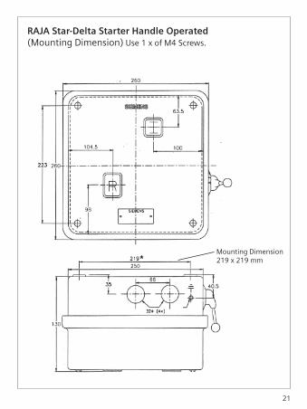
RAJA Star-Delta Starter Handle Operated (Mounting Dimension) Use 1 x of M4 Screws.
Mounting Dimension219 x 219 mm

22
Raja Star-Delta Starter (Automatic)
R
361
31921
935
261
130
M4
125
60110

23
5. Trouble shooting
Trouble & Possible Cause What to do
Contactors
a) Contacts chatter
1) Low voltage-coil not picking 1) Correct voltage condition. In up properly case there is persistent low-voltage, change to a lower voltage coil.
2) Broken Pole Shading ring. 2) Get contactor replaced.
3) Poor contact in control circuit 3) Clean contacts
4) Control circuit connections 4) Tighten the connections loose
b) Welding or overheating
1) Low voltage preventing 1) Correct voltage condition. In magnet from sealing case of persistent low voltage, change to a lower voltage coil
2) Short circuit 2) Trace and correct fault, and check to be sure that fuse rating is correct.
3) Foreign matter preventing 3) Clean contacts with contact closing suitable solvent.

c) Short life of contact tips
1) Filling or Dressing 1) Do not file silver faced contacts. Rough spots or discoloration will not harm contacts. Silver oxide is a good conductor of electricity.
2) Weak contact pressure 2) Check for obstructions
d) Noisy magnets
1) Broken Shading ring 1) Mechanical life over. Replace contactor.
2) Dirt or rust on magnet faces 2) Clean with suitable solvent.
e) Failure to pick-up and seal
1) Low voltage 1) Check system voltage. In case of persistent low voltage, change to a lower voltage coil
2) Coil open or shorted 2) Replace the coil
3) Mechanical obstruction 3) Clean and check for free movement of contact assembly.
f) Failure to drop out
1) Voltage not removed 1) Check wiring of the coil circuit
2) Worn or rusted parts causing 2) Replace such parts binding
24

25
3) Residual magnetism due to 3) Replace the contactor lack of air gap in magnet path
4) Gummy substance on pole 4) Clean with suitable solvent face causing binding
g) Overheating of coil
1) Over-voltage 1) Check and correct terminal voltage/replace with a higher voltage coil
2) Under voltage-failure of 2) Correct terminal voltage/ magnet to seal in replace with a lower voltage coil
3) High ambient temperature 3) Replace starter in a more suitable area
4) Short circuit turns in coils 4) Replace coil caused by mechanical damage or corrosion
5) Dirt or rust on pole faces 5) Clean pole faces increasing air gap
Bimetal Overload Relay
a) Tripping often
1) Incorrect bimetal setting 1) Set relay properly
2) Sustained overload 2) Check for faults/excessive motor currents
3) Reduced supply voltage 3) Do not restart till voltage improves

b) Failure to trip (causing motor burn out)
1) Wrong bimetal setting 1) Check rating and set the relay properly, to actual load current in case of DOL or 0.58 times load current in case of star-delta starter.
2) Mechanical binding due to 2) Replace the relay dirt, corrosion etc.
3) Incorrect control wiring 3) Check circuit
c) Welding of contacts
1) Back up protection fuse 1) Replace relay and refer to rating too high Selection Table for proper back up fuse rating
Fuses (HRC type cartridge)
a) Constant blowing of fuses
1) Short circuit 1) Check the feeder circuit with a megger
2) Fuse rating too low. 2) Refer to Selection Table and select proper fuse
b) Fuses not blowing under short circuit conditions
1) Fuse rating too high 1) Refer Selection Table and install suitable fuse
26
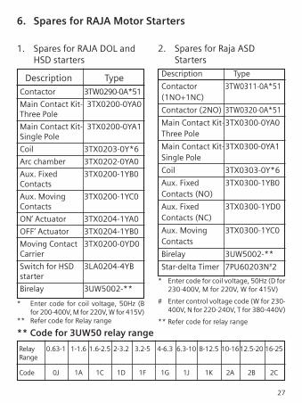
6. Spares for RAJA Motor Starters
27
1. Spares for RAJA DOL and HSD starters
Description Type Contactor 3TW0290-0A*51
Main Contact Kit- 3TX0200-0YA0 Three Pole
Main Contact Kit- 3TX0200-0YA1 Single Pole
Coil 3TX0203-0Y*6
Arc chamber 3TX0202-0YA0
Aux. Fixed 3TX0200-1YB0 Contacts
Aux. Moving 3TX0200-1YC0 Contacts
ON’ Actuator 3TX0204-1YA0
OFF’ Actuator 3TX0204-1YB0
Moving Contact 3TX0200-0YD0 Carrier
Switch for HSD 3LA0204-4YB starter
Birelay 3UW5002-**
* Enter code for coil voltage, 50Hz (B for 200-400V, M for 220V, W for 415V)** Refer code for Relay range
2. Spares for Raja ASD Starters Description Type
Contactor 3TW0311-0A*51 (1NO+1NC)
Contactor (2NO) 3TW0320-0A*51
Main Contact Kit- 3TX0300-0YA0 Three Pole
Main Contact Kit- 3TX0300-0YA1 Single Pole
Coil 3TX0303-0Y*6
Aux. Fixed 3TX0300-1YB0 Contacts (NO)
Aux. Fixed 3TX0300-1YD0 Contacts (NC)
Aux. Moving 3TX0300-1YC0 Contacts
Birelay 3UW5002-**
Star-delta Timer 7PU60203N#2
* Enter code for coil voltage, 50Hz (D for 230-400V, M for 220V, W for 415V)
# Enter control voltage code (W for 230- 400V, N for 220-240V, T for 380-440V)
** Refer code for relay range
** Code for 3UW50 relay range
Relay 0.63-1 1-1.6 1.6-2.5 2-3.2 3.2-5 4-6.3 6.3-10 8-12.5 10-16 12.5-20 16-25 Range
Code 0J 1A 1C 1D 1F 1G 1J 1K 2A 2B 2C

28
Maximum Full Load Current for different types of motors (Reference IS 8789/9283/996)
Max. Full Load Current (Amp)
Motor Rating 3 Ph, 415V, 4P 3 Ph, 415V, 2P 1 Ph, 240V Squirrel Cage Submersible Motor CSIR or Split-Phase IS 8789 : 1996 IS 9283 : 1995 IS 996 : 1979 HP kW (Table 4) (Table 2) (Table 9)
0.33 0.25 — — 3.8
0.5 0.37 1.4 — 6
0.75 0.55 1.7 — 7
1 0.75 2.2 — 10
1.5 1.1 2.9 3.25 13
2 1.5 3.8 4.5 18
3 2.2 5.1 6.5 —
5 3.7 8.1 10 —
7.5 5.5 11.4 14.5 —
10 7.5 15.4 19.5 —
12.5 9.3 19.5 25 —
15 11 23 29 —
20 15 32 39 —
25 18.5 38.5 — —
Note : The above table gives the max. full load current for various motors commonly used. It is recommended that the above table be referred to in conjuction with motor name plate data, before selecting the starter with appropriate relay range.

Notes :

Notes :

Notes :
Product upgradation is a continuous process. Hence, data in this
booklet is subject to change without prior notice. For further
information, please contact our nearest Branch Office.
Siemens Ltd.
Siemens Ltd.Industry Sector Control Products R&D Technology Centre Kalwa Works, Thane Belapur Road Thane - 400 601 Fax: +91 22 33265627 E-mail: [email protected]
Aurangabad Mobile: +91 9049005024
Belgaum ( : +91 831 2495156 Mobile: +91 9740277991
Bhilai Mobile: +91 7869922211
Bhopal Mobile: +91 9977228084
Boisar Mobile: +91 9820533850
Calicut Mobile: +91 9645963636
Cochin ( : +91 4028611/22 Mobile: +91 9387384848 Mobile: +91 9744511109
Dehradun ( : +91 135 2528212 Mobile: +91 8650404404
Durg Mobile: +91 9425016197
Durgapur Mobile: +91 9874343052
Goa Mobile: +91 9860053365
Guwahati ( : +91 361-2230836 Fax: +91 361-2230836
Haridwar ( : +91 1334 251943 Mobile: +91 9897070133
Haridwar Mobile: +91 9621083333
Hospet Mobile: +91 9901400227
Hubli ( : +91 836 2282947 Mobile: +91 9880003724
Indore Mobile: +91 9926939993
Indore Mobile: +91 9713013050
Jalandhar Mobile: +91 9876047929
Jamshedpur Mobile: +91 9771498151
Jamshedpur Mobile: +91 9836311093
Jodhpur ( : +91 291 2760371 Mobile: +91 9828327200
Kanpur Mobile: +91 8009900939
Kolhapur
( : +91 231 2663330 Mobile: +91 9881465421
Ludhiana Mobile: +91 9815502480
Ludhiana Mobile: +91 9878098612
Ludhiana Mobile: +91 9888484066
Madurai Mobile: +91 9894617776
Mangalore Mobile: +91 9632835364
Meerut Mobile: +91 9837049091
Mysore Mobile: +91 9900855779
Nashik Mobile: +91 9822193204
Patna Mobile: +91 9771414108
Pondicherry Mobile: +91 9840143536
Sales Offices:
Territory managers:
Ahmedabad ( : +91 79 30927600 Fax: +91 79 30927699
Baroda ( : +91 265 3039100 Fax: +91 265 3039190
Bengaluru 1( : +91 80 33422000 Fax: +91 80 33424131
Bhubaneswar ( : +91 674 2581220 Fax: +91 674 2581330
Chandigarh ( : +91 172 4690300 Fax: +91 172 4690399
Chennai ( : +91 44 30474000 Fax: +91 44 30474088
Coimbatore ( : +91 422 3076300 Fax: +91 422 3076310
Gurgaon ( : +91 124 2842000, 3810200
Hyderabad ( : +91 40 30922500 Fax: +91 40 30923145
Jaipur ( : +91 141 5152108 Fax: +91 141 2370482
Kolkata ( : +91 33 30939000 Fax: +91 33 30939010, 30939013
Lucknow ( : +91 522 4031022, 4031000 Fax: +91 522 4031019
Mumbai ( : +91 22 39663000 Fax: +91 22 39663721
Nagpur ( : +91 712 3093000 Fax: +91 712 3093111
Pune ( : +91 20 30466000 Fax: +91 20 30466060
Vishakhapatnam ( : +91 891 3050200 Fax: +91 891 3050222
Raipur Mobile: +91 9425601849
Rajkot Mobile: +91 9825021026
Renukoot ( : +91 5446 254693 Mobile: +91 9838007897
Rourkela Mobile: +91 9438529778
Rudrapur Mobile: +91 9720999887
Salem ( : +91 427 2401981 Mobile: +91 9894617772
Surat Mobile: +91 9879510191
Trichy ( : +91 431 4345621 Mobile: +91 9840843121
Trivandrum Mobile: +91 9895979604
Udaipur ( : +91 294 2430345 Mobile: +91 9829039120
Vapi Mobile: +91 9687668690
Vijayawada ( : +91 866 3060833 Mobile: +91 98664 63639
Siemens Ltd. SGR-01-103-036This replaces SGR-01-103-020