a power flow method using a new bus type for computing ... · • if the load bus voltage angle is...
TRANSCRIPT

Rensselaer Polytechnic Institute Electrical, Computer, and Systems Engineering
EPCC Workshop – 06/03/2013 J. H. Chow 1
12th International Workshop on Electric Power Control Centers
A Power Flow Method using a New Bus Type for
Computing Steady-State Voltage Stability Margins
Scott G. Ghiocel and Joe H. Chow
Electrical, Computer, and Systems Engineering Rensselaer Polytechnic Institute
June 3, 2013
Rensselaer Polytechnic Institute Electrical, Computer, and Systems Engineering
EPCC Workshop – 06/03/2013 J. H. Chow 2
• NSF/DOE CURENT ERC: Center for Ultra-wide Resilient Electric Energy Transmission Networks
• DOE CERTS: Voltage stability applications using synchrophasor data, in collaboration with BPA and SCE
Voltage Stability Projects at Rensselaer

Rensselaer Polytechnic Institute Electrical, Computer, and Systems Engineering
EPCC Workshop – 06/03/2013 J. H. Chow 3
CERTS Project Overview
• Traditional voltage stability analysis approaches
• Full-order detailed model – off-line analysis ; real-time analysis with SCADA measurements or SE solutions; an example is the VSTAB program; high computation burden and dependent on the load model
• Single-load stiff-bus model, such as the voltage instability predictor (VIP) approach; applicable to radial systems, and also dependent on load models
• This project aims at developing an alternative (hybrid) approach with less computation than VSTAB type programs, but capable of handling more complex power transfer paths
Increasing level of complexity
Single load center, VIP model
Full detailed model, SCADA based
Hybrid model, PMU based, high-voltage
transmission grid

Rensselaer Polytechnic Institute Electrical, Computer, and Systems Engineering
EPCC Workshop – 06/03/2013 J. H. Chow 4
Project Overview
• Consider the voltage stability analysis of a more complex power transfer path like the Pacific AC Intertie:
• Network characteristics
• Large number of injection and out flow points
• Loads with multiple infeeds
• Important to know
• PMU data – as a means of obtaining actual voltage sensitivity and measuring injections and outflows
• Network parameters
• Flow sensitivities at injection and outflow points
• Multiple vulnerabilities and reactive power supply at each location
The Dalles
(3)Inflow
Grizzly
(3)
Malin
(2) (2) (2)R. Mtn T. Mtn
(1) Tracy/ Tesla
Moss Landing
Inflow
(3)
Diablo Canyon
Inflow
(2)
Midway
(3)
Vincent
Victorville/ Adelanto
To other load buses
Inflow from East

Rensselaer Polytechnic Institute Electrical, Computer, and Systems Engineering
EPCC Workshop – 06/03/2013 J. H. Chow 5
PMU-Based Voltage Stability Analysis for New York
• Use PMU data from loss-of-generation disturbance events to construct external system equivalents (at Buses 1, 2, 3, 7, and 8)
• Compute PV-curves using PMU data-based model
7
3
2
5 9
4
6
1
SVC
8External
system

Rensselaer Polytechnic Institute Electrical, Computer, and Systems Engineering
EPCC Workshop – 06/03/2013 J. H. Chow 6
PV Curves for a Stability Interface in Central NY
0 2 4 6 8 10 12 14
0.88
0.9
0.92
0.94
0.96
0.98
1
1.02
1.04
1.06
Change in Power Transfer (p.u.)
Vo
ltag
e M
ag
nit
ud
e (
p.u
.)
Bus 1 Data
Bus 1 Model
Bus 8 Data
Bus 8 Model
SVC Saturation Limit
Rensselaer Polytechnic Institute Electrical, Computer, and Systems Engineering
EPCC Workshop – 06/03/2013 J. H. Chow 7
Steady-State Voltage Stability Margin Calculation
• Difficulty – the power flow Jacobian J becomes singular at the voltage collapse point. The Newton-Raphson method does not converge, sometimes far from the voltage collapse point (the Gauss-Seydel method will have same problem).
• Method of homotopy (continuation power flow method) – introduces a load parameter so that the dimension of Jacobian matrix J increases by 1 to make J nonsingular. Special software packages using such methods to compute voltage stability (VS) margin have been developed, such as CPFLOW.
• Our approach – define a new bus type and take the singularity directly out of J
Rensselaer Polytechnic Institute Electrical, Computer, and Systems Engineering
EPCC Workshop – 06/03/2013 J. H. Chow 8
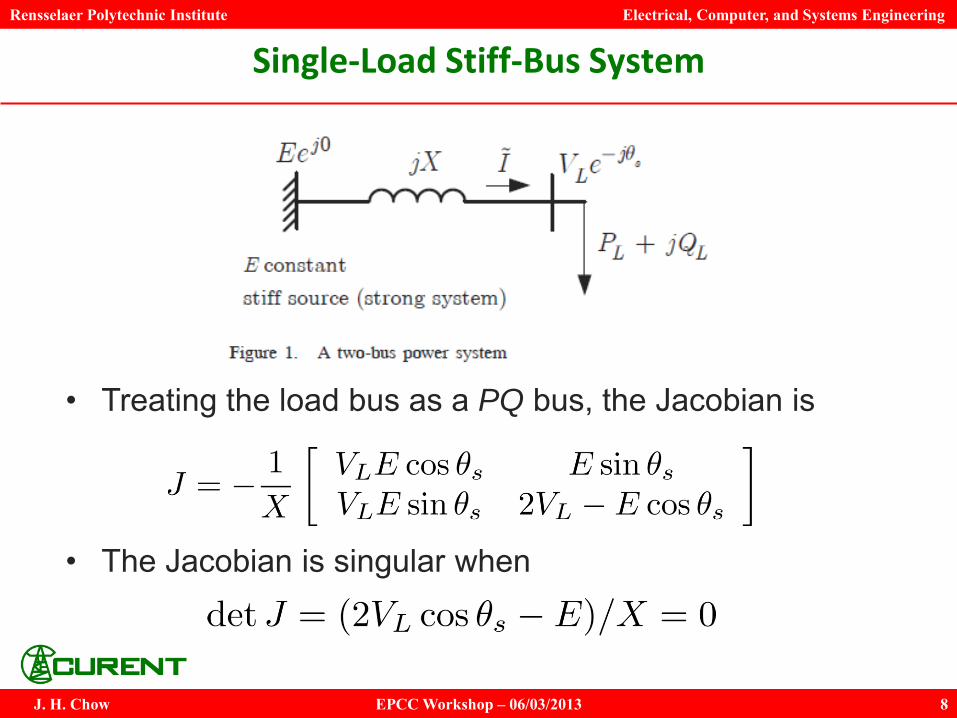
Single-Load Stiff-Bus System
• Treating the load bus as a PQ bus, the Jacobian is
• The Jacobian is singular when
Rensselaer Polytechnic Institute Electrical, Computer, and Systems Engineering
EPCC Workshop – 06/03/2013 J. H. Chow 9
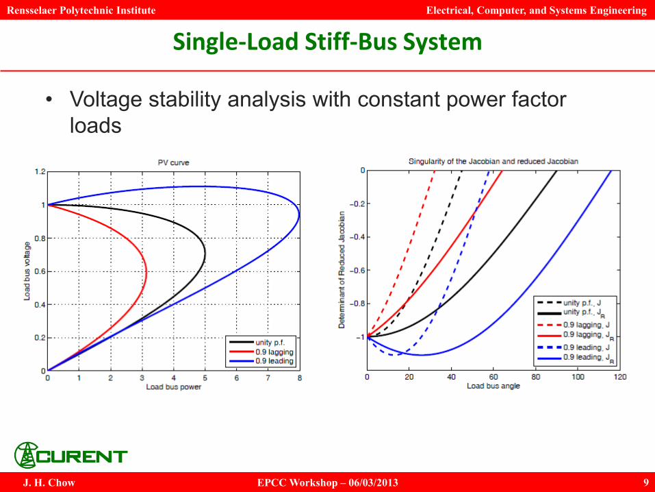
Single-Load Stiff-Bus System
• Voltage stability analysis with constant power factor loads

Rensselaer Polytechnic Institute Electrical, Computer, and Systems Engineering
EPCC Workshop – 06/03/2013 J. H. Chow 10
Load Bus Angle Variations
• Load bus voltage angle is seldom analyzed in this context

Rensselaer Polytechnic Institute Electrical, Computer, and Systems Engineering
EPCC Workshop – 06/03/2013 J. H. Chow 11
New Idea of Specifying Load Bus Voltage Angle
• If the load bus voltage angle is specified, the power flow analysis reduces to 1 nonlinear equation of solving for the reactive power balance at the load bus.
• For a constant power factor load, the reduced Jacobian is
• This value becomes 0 not at the critical voltage collapse point, but at VL = 0 (see right figure on p. 9)
Rensselaer Polytechnic Institute Electrical, Computer, and Systems Engineering
EPCC Workshop – 06/03/2013 J. H. Chow 12
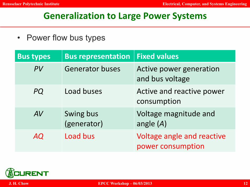
Generalization to Large Power Systems
• Power flow bus types
Bus types Bus representation Fixed values
PV Generator buses Active power generation and bus voltage
PQ Load buses Active and reactive power consumption
AV Swing bus (generator)
Voltage magnitude and angle (A)
AQ Load bus Voltage angle and reactive power consumption

Rensselaer Polytechnic Institute Electrical, Computer, and Systems Engineering
EPCC Workshop – 06/03/2013 J. H. Chow 13
Advantages of using an AQ Bus
• With the angle of the AQ load bus specified, only the reactive power balance equation is included in the load flow solution. Thus the dimension of the reduced Jacobian JR is lowered by 1, eliminating the singularity.
• The active power consumption P at the AQ bus is determined from the converged power flow solution – it cannot be specified ahead of time.
• For voltage stability margin calculation, the AQ bus is designated as one of the buses with large load increases. The separation angle between the swing bus and the AQ bus is progressively increased to generate the PV curve and thus the VS margin.

Rensselaer Polytechnic Institute Electrical, Computer, and Systems Engineering
EPCC Workshop – 06/03/2013 J. H. Chow 14
Advantages of using an AQ Bus
• The AQ-bus method can accommodate constant power factor loads by adjusting the rows of the reduced Jacobian JR
• The method also allows load increases at multiple load buses with supply coming from multiple generators, using only 1 AQ bus
• All features in a regular power flow program can be used, such as sparse factorization, tap changing transformers, reactive power generation limits, and decoupled power flow, because this new method conforms to the power flow program structure
Rensselaer Polytechnic Institute Electrical, Computer, and Systems Engineering
EPCC Workshop – 06/03/2013 J. H. Chow 15
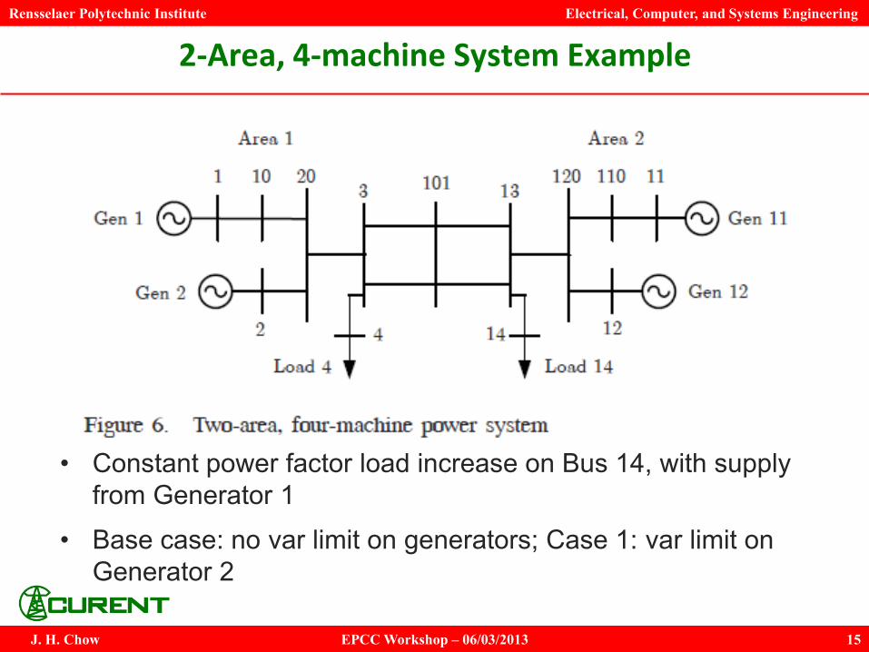
2-Area, 4-machine System Example
• Constant power factor load increase on Bus 14, with supply from Generator 1
• Base case: no var limit on generators; Case 1: var limit on Generator 2
Rensselaer Polytechnic Institute Electrical, Computer, and Systems Engineering
EPCC Workshop – 06/03/2013 J. H. Chow 16
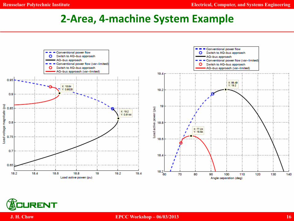
2-Area, 4-machine System Example
Rensselaer Polytechnic Institute Electrical, Computer, and Systems Engineering
EPCC Workshop – 06/03/2013 J. H. Chow 17
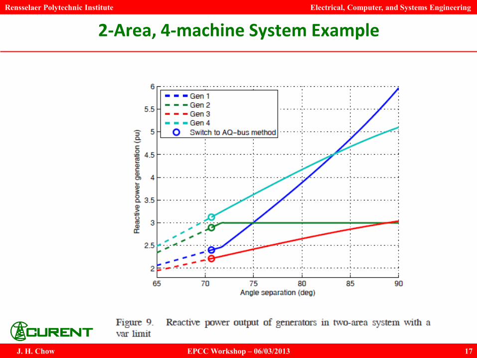
2-Area, 4-machine System Example

Rensselaer Polytechnic Institute Electrical, Computer, and Systems Engineering
EPCC Workshop – 06/03/2013 J. H. Chow 18
NPCC 48-machine System Example

Rensselaer Polytechnic Institute Electrical, Computer, and Systems Engineering
EPCC Workshop – 06/03/2013 J. H. Chow 19
NPCC 48-machine Gen/Load Schedule
50 36
30
16 15 4

Rensselaer Polytechnic Institute Electrical, Computer, and Systems Engineering
EPCC Workshop – 06/03/2013 J. H. Chow 20
NPCC 48-machine Contingency List
1 2
3 4 5
Rensselaer Polytechnic Institute Electrical, Computer, and Systems Engineering
EPCC Workshop – 06/03/2013 J. H. Chow 21
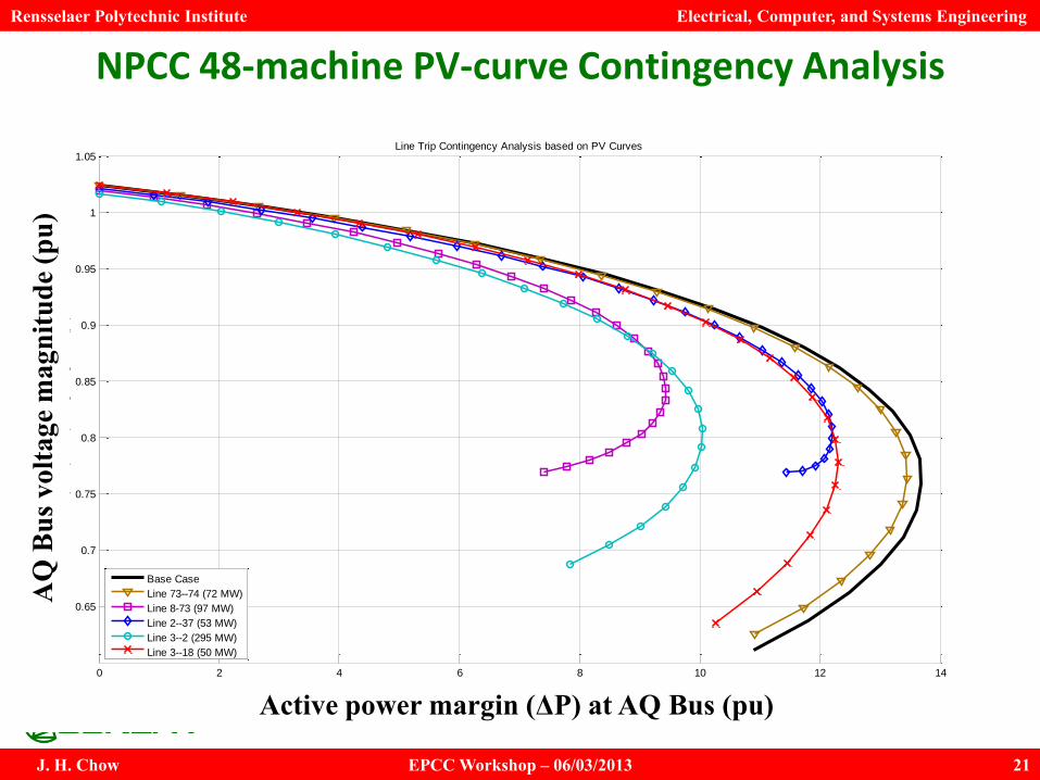
NPCC 48-machine PV-curve Contingency Analysis
0 2 4 6 8 10 12 14
0.65
0.7
0.75
0.8
0.85
0.9
0.95
1
1.05
Active power loading margin at AQ-bus (Bus 16) (pu)
AQ
-bus (
Bus 1
6)
voltage m
agnitude (
pu)
Line Trip Contingency Analysis based on PV Curves
Base Case
Line 73--74 (72 MW)
Line 8-73 (97 MW)
Line 2--37 (53 MW)
Line 3--2 (295 MW)
Line 3--18 (50 MW)
AQ
Bus
vol
tage
mag
nitu
de (p
u)
Active power margin (ΔP) at AQ Bus (pu)

22
Acknowledgements
This work was supported primarily by the ERC Program of
the National Science Foundation and Department of Energy
under NSF Award Number EEC-1041877.
Other US government and industrial sponsors of CURENT
research are also gratefully acknowledged.