a practical viewpoint
TRANSCRIPT
IEE
E I
ND
US
TRY
AP
PLI
CA
TIO
NS
MA
GA
ZIN
E •
JA
N|
FE
B 2
00
6 •
WW
W.I
EE
E.O
RG
/IA
S
50
1077-2618/06/$20.00©2006 IEEE
B Y J O H N P . N E L S O N
HE THREE-PHASE, FOUR-WIRE,
multigrounded distribution system has
been selected by most utilities in North
America as the medium-voltage distribu-
tion system of choice, even though many utilities started
with a three-wire, ungrounded delta system. The reasons
for the development of the three-phase, four-wire, multi-
grounded systems involve a combination of safety and
economic considerations. The three-phase, four-wire
multigrounded design has been successfully used for
many years and is well documented in standards, includ-
ing the National Electrical Safety Code (NESC) [1], and the
T
A practical viewpoint.
©A
RT
VIL
LE, L
LC.
IEE
E IN
DU
STR
Y A
PP
LICA
TION
S M
AG
AZIN
E •
JAN
|F
EB
20
06
• W
WW
.IEE
E.O
RG
/IAS
51
National Electrical Code (NEC) [2]. Have there been prob-lems associated with this system? Yes. Are there reason-able solutions available to minimize these problems?Absolutely! Should the use of the multigrounded systembe eliminated? This article will show that the answer tothe last question is absolutely not.
The earth is an electromagnetic circuit, with northand south magnetic poles and with an ionosphere madeup with charged particles. During electromagneticstorms caused by sunspot activity, observations havebeen made showing potential gradients (stray voltages)on the earth’s surface of 1–10 V/km [3]. These voltagegradients have occurred since the origin of the earth andwill continue to occur in the future. Man and animalshave lived with these stray voltages and associated straycurrents with no apparent adverse reactions. And, iffound that there were hazards associated with them,there is little that can be done about stopping it at itssource, the sun. Therefore, we live in a world wherestray voltages and stray currents are natural.
Next, there are many hazards associated with the gen-eration, transmission, and distribution of electricity. Thefollowing is a list of a few of those hazards:
■ contact with energized parts■ electrical arc flashes■ auto accidents involving power poles■ drowning in water associated with hydroelectric plants■ illness and deaths from the gases emitted from coal
and oil-fired generation plants■ auto accidents involving trains transporting coal to
electric generating stations.The risks associated with these hazards are mini-
mized with sound engineering, construction, and main-tenance practices. The benefits of safely using electricityfar outweigh the risks involved in its generation, trans-mission, and distribution. Rather than outlawing theuse of electricity due to its inherent hazards, engineer-ing standards and designs have beendeveloped to minimize the hazardsand to mitigate the problems to alevel of acceptable risk.
Acceptable RisksTo explain the term “acceptablerisk,” let us consider a commoneveryday risk. Each year, over 50,000lives are lost due to automobile acci-dents in the United States. Through-out the world, that figure is mostlikely higher, but few people wouldagree that saving those 50,000 livesis worth outlawing automobiles. Sta-tistically speaking, every person inthe United States has approximatelya one in 5,000 chance of dying in anautomobile accident in any givenyear. We consider that probability an“acceptable risk.”
Another similar statistic is that in2001, 491 people across the UnitedStates died in train-vehicle collisions
[4]. Many more were injured at rail crossings. Using simi-lar statistical calculations, on the average, a person has aone in 500,000 chance of being killed in a car-train colli-sion. The number of such deaths could be drasticallyreduced, if not eliminated, by eliminating railroad cross-ings. This could be accomplished by constructing expen-sive overpasses at each rail crossing. Safety crossings can beinstalled at approximately US$180,000 each and bridgesat US$4 million. In Colorado alone, there exist 1,368 railcrossings that are not equipped with any type of warningdevice [5]. The cost to implement better safety measuresfor those 1,368 rail crossings is estimated to be US$246million to place warning signals at each of those crossingsor US$5.47 billion to place bridges at all of those cross-ings. And Colorado only accounts for 1% of the fatalitiesin the United States [4]. While 19 fatalities occurred inColorado from 1999 to present, Texas was Number 1 inthe nation, with 161 deaths, and California had 122recorded fatalities. While those numbers of fatalities arealarming, they show that there are risks to people and weaccept those risks in our everyday life. There are manyother examples of similar risks, including being struck bylightning, being involved in an airplane crash, and manyothers. The chances of being injured or killed in such anaccident in any given year is part of life, will never betotally eliminated, and is considered an “acceptable risk.”
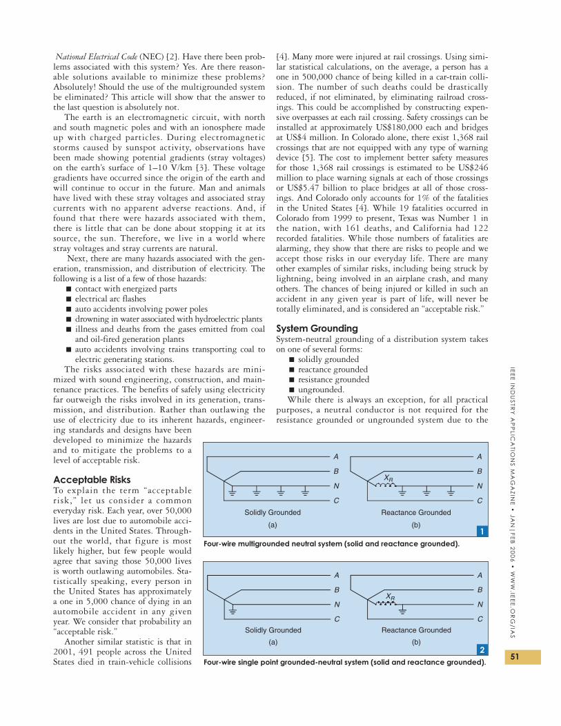
System GroundingSystem-neutral grounding of a distribution system takeson one of several forms:
■ solidly grounded■ reactance grounded■ resistance grounded■ ungrounded.While there is always an exception, for all practical
purposes, a neutral conductor is not required for theresistance grounded or ungrounded system due to the
Four-wire single point grounded-neutral system (solid and reactance grounded).
XRN
C
B
A
Reactance GroundedSolidly Grounded
(b)(a)
B
C
N
A
2
Four-wire multigrounded neutral system (solid and reactance grounded).
Solidly Grounded
C
N
A
B
Reactance Grounded
(a) (b)
B
C
N
A
XR
1

IEE
E I
ND
US
TRY
AP
PLI
CA
TIO
NS
MA
GA
ZIN
E •
JA
N|
FE
B 2
00
6 •
WW
W.I
EE
E.O
RG
/IA
S
52
fact that no neutral current is expected to flow. There-fore, only limited discussion of those two systems willbe included. That leaves the solidly-grounded and reac-tance-grounded systems that will be discussed in greaterdetail in this article. The latter two systems can have asingle-point grounded or multigrounded neutral. Ingeneral, the systems shown in Figures 1–5 are theoptions available for use.
Figure 1 depicts the multigrounded neutral system forthe solidly grounded and reactance grounded systemscommonly used by electric utilities in North America.The neutral-grounding reactor is used by some utilities toreduce the available ground-fault current while at thesame time maintaining an effectively grounded system.The NESC provides a definition for an “effectivelygrounded system”:
An effectively grounded system is intentionally con-nected to earth through a ground connection or con-nections of sufficiently low impedance and havingsufficient current carrying capacity to limit thebuildup of voltages to levels below that which mayresult in undue hazard to persons or to connectedequipment [1].
There are other, more technical issues of an effective-ly grounded system that will be discussed later inthis article.
Figure 2 is different from Figure 1 in that the sys-tem neutral is grounded only at one point. The groundconnection would typically be located in the distribu-tion substation.
Figure 3 shows the connections for a solidly grounded,reactance-grounded, and resistance-grounded three-phase,three-wire system.
Figure 4 shows a three-wire ungrounded delta system,and Figure 5 shows a three-wire ungrounded-wye system.For personnel and equipment safety, neither of these twosystems is currently recommended for modern-day sys-tems. Some still exist, but very few are currently designedand constructed as an ungrounded system.
The differences between the multigrounded systemsin Figure 1 and the single-point grounded systemsshown in Figure 2 may appear insignificant, but the safe-
ty and economic differences aresignificant, as will be explained inmore detail later.
The three-phase, three-wire sys-tems shown in Figure 3 are com-monly used in an industrial powersystem. Industrial power systemstypically have a large number ofthree-phase motors and have noneed for neutral-connected loads.Therefore, industrial users willusually dispense with the need forthe fourth-wire neutral.
Safety and CodeConsiderationsThe multigrounded system is ref-erenced in both the NESC and theNEC. The NEC requires single-point grounding on low-voltagesystems (600 V and below). How-ever, the NEC allows the use of amultigrounded system for volt-
ages above 600 V. On the other hand, the NESC is quitespecific that a three-phase, four-wire system must have amultigrounded neutral. Otherwise, the required clear-ances may need to be increased to that of an ungroundedsystem. Furthermore, a single-point grounded neutral canno longer be considered effectively grounded, can have asubstantial voltage present, and may need to be isolatedby using additional clearances.
Code and safety considerations include:A. NESC Section 096.C: Multi-Grounded Systems:
The neutral, which shall be of sufficient size andampacity for the duty involved, shall be connected to
Three-wire, ungrounded delta connected transformer.
A
B
C4
Three-wire, ungrounded-wye connected transformer.
C
A
B
5
Three-wire, single-point grounded system without a neutral (solid, reactance, and
resistance grounded).
Reactance GroundedSolidly Grounded
(b)(a)
XR
C
B
A
B
C
A
Resistance Grounded
(c)
C
A
B
R
3

IEE
E IN
DU
STR
Y A
PP
LICA
TION
S M
AG
AZIN
E •
JAN
|F
EB
20
06
• W
WW
.IEE
E.O
RG
/IAS
53
a made or existing electrode at each transformer loca-tion and at a sufficient number of additional pointswith made or existing electrodes to total not less thanfour grounds in each 1.6 km (1 mi) of the entire line,not including grounds at individual services.
B.NEC Article 250 Part X Grounding of Systems andCircuits 1 kV and Over (High Voltage) Section 250.180(B) Multiple Grounding:The neutral of a solidly grounded neutral systemshall be permitted to be grounded at more than onepoint [2].
C.250.180 (D) Multigrounded Neutral Conductor:■ ground each transformer■ ground at 400-m intervals or less■ ground shielded cables where exposed to person-
nel contactD.Safety Concerns on Cable Shields:
Medium- and high-voltage cables typically have cableshields (NEC requirement above 5 kV) that need to begrounded. There are several reasons for this shield: [6]■ to confine electric fields within the cable■ to obtain uniform radial
distr ibution of the electric field
■ to protect againstinduced voltages
■ to reduce the hazard ofshock.If the shield is not
grounded, the shock hazardcan be increased. With theshield grounded at one point,induced voltage on the shieldcan be significant and createa shock hazard. Therefore, itis common practice to applymultiple grounds on theshield to keep the voltagelimited to 25 V. This practiceof multigrounding cableshields includes the ground-ing of concentric neutrals onpower cables thereby extend-ing the need for multi-grounding of neutrals on thepower system.
Protective RelayingConsiderationsProtective relays need to senseabnormal conditions, especiallythose involving a ground fault.The single-point grounded sys-tem, with or without a neutralconductor, provides the easiestmethod for sensing ground faults.Any current flowing into theground should be consideredabnormal (excluding normalcharging current). Three means ofsensing ground faults are:
■ A current transformer (CT) in the location where theneutral is grounded can be used to sense the groundfault (zero sequence) current [Figure 6(a)].
■ A zero-sequence CT enclosing the three-phase andneutral conductors [Figure 6(b)].
■ Four CT residue circuit (Three CT residual withneutral CT cancellation) [Figure 6(c)].
Protecting against ground faults on a multigroundedneutral system is more difficult than the single pointgrounded system, since both neutral and ground-fault cur-rents must be considered. Neutral current and, likewise,ground-fault current can flow in both the neutral and theground. So, consideration must be given to the amount ofneutral current that may flow in the circuit, and theground fault setting must be above this neutral current.This is self-explanatory from Figure 7.
While the sensing of the ground-fault current in thesingle-point grounded system is less complex than in themultigrounded system, the amount of ground-fault cur-rent on the single-point grounded system may be greatlylimited due to the fact that all ground-fault current must
Current distribution in multi-grounded system. (a) Neutral current flowing in neutral
and ground. (b) Ground-fault current flowing in the neutral and ground.
IN1
IFault =IF1+IF2
IF2
IF1
ILoad =IN1+IN2
IN1
IN2
IL
7
Ground current sensing. (a) Current transformer in ground. (b) Zero sequence CT
including neutral. (c) Residual current with neutral cancellation.
C
N
A
B
51 G
(a)
A
C
N
B
Zero Sequence
51 G
(b)
C
A
N
B
51 G
(c) 6

IEE
E I
ND
US
TRY
AP
PLI
CA
TIO
NS
MA
GA
ZIN
E •
JA
N|
FE
B 2
00
6 •
WW
W.I
EE
E.O
RG
/IA
S
54
return through the earth. This is especially true where theearth resistivity is high, the soil is frozen, or the soil isextremely dry. Therefore, the multigrounded neutral sys-tem imcreases the probability of sensing a ground faultunder all conditions and, therefore, provides more andmore reliable, and, thus, safer, means of isolating groundfaults from the system.
Earth Resistance and ReactanceEarly research by Carson and others into the developmentof transmission line impedances showed that the earthresistance, Re, is frequency dependent and earth resistivityindependent [7], and (1) shows this relationship.
Re = 0.00296 f �/km, (1)
where Re = earth resistance in ohms per kilometer.However, it is interesting to note that the earth reac-
tance is dependent on both frequency and earth resistivity,as seen in (2) and Table 1 [7].
Xe = 0.004338 f log10[4.6656 × 10⁶(ρ/f )]�/km, (2)
whereXe = earth reactance in �/kmf = frequency in Hertzρ = earth resistivity in �-m.
Based on (1) and (2), Table 1 shows Re and Xe for 60Hz with various soil resistivities.
Soil resistivity varies considerably by types of soils. SeeTable 2 [8]. However, it is important to look at two addi-tional aspects for soil resistivity: moisture and temperature.
Soil resistivity of the permafrost is typically in therange of 3,500–4,000 �-m [9]. Soil resistivity is tempera-ture dependent, especially once the temperature fallsbelow freezing. For example, clay may have a soil resistivi-ty in the range as low as 15 �-m at 10 ◦C, 20 �-m near 0◦C and 1,000 �-m at −15 ◦C. Another example is silt inthe Fairbanks, Alaska, area, which has a relatively constantsoil resistivity of 300 �-m down to freezing to as high as8,000 �-m at −15 ◦C [10].
The interesting aspect of the previous discussions onsoil resistivity can be seen in (3), the resistance of a singleground rod [8].
R = ρ
2π
(ln
4 L
a− 1
)�, (3)
where,L = length of rod (m)a = radius of rod (m)ρ = resistivity of soil (�-m).
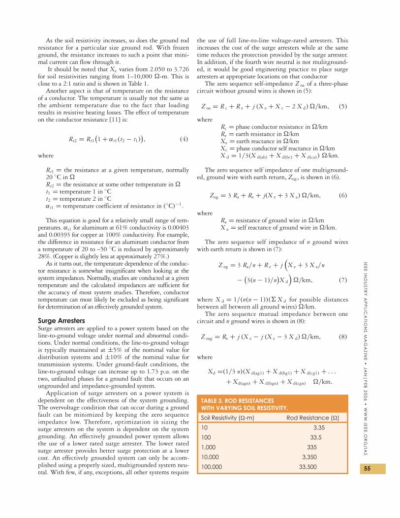
The rod resistance of a 16 mm × 3 m ground rod forvarying soil resistivities (10–100,000 �-m) is shown inTable 3.
TABLE 1. Re AND Xe @ f = 60 HZ.
ρ Re Xe�-m (�/km) (�/km)
1 0.178 1.273
5 0.178 1.455
10 0.178 1.533
50 0.178 1.715
100 0.178 1.793
500 0.178 1.975
1000 0.178 2.054
5000 0.178 2.236
10000 0.178 2.314
APPENDIX 1—SOIL GROUP SYMBOLSThe following is a list of soil group symbols thatwere referenced in Table 2: [8]
Symbol Soil Description
GW Well graded gravel, gravel-sand mixtures or no fines
GP Poorly graded gravels, grave-sand mixtures, little or no fines
GC Clayey gravel, poorly graded gravel, sand clay mixtures
SM Silty sands, poorly graded sand-silt mixtures
SC Clayey sands, poorly graded sand-clay milxtures
ML Silty or clayey fine sands with slight plasticity
MH Fine sandy or silty soils, elastic siltsCL Gravely clays, sandy clays, silty clays,
lean claysCH Inorganic clays of high plasticity
TABLE 2. TYPICAL SOIL RESISTIVITYAND GND ROD (16 MM ××× 3 M) RESISTANCE.
Range of RodResistivity (16 mm × 3 m)
Soil Group* (�-m) Resistance (�)
GP 1–2.5 k 300–750
GW 600–1000 180–300
GC 200–400 60–120
SM 100–500 30–150
SC 50–200 15–60
ML 30–80 9–24
MH 80–300 24–90
CL 25–60 17–18
CH 10–55 3–16
(*See Appendix 1 for soil group types)
IEE
E IN
DU
STR
Y A
PP
LICA
TION
S M
AG
AZIN
E •
JAN
|F
EB
20
06
• W
WW
.IEE
E.O
RG
/IAS
55
As the soil resistivity increases, so does the ground rodresistance for a particular size ground rod. With frozenground, the resistance increases to such a point that mini-mal current can flow through it.
It should be noted that Xe varies from 2.050 to 3.726for soil resistivities ranging from 1–10,000 �-m. This isclose to a 2:1 ratio and is shown in Table 1.
Another aspect is that of temperature on the resistanceof a conductor. The temperature is usually not the same asthe ambient temperature due to the fact that loadingresults in resistive heating losses. The effect of temperatureon the conductor resistance [11] is:
Rt2 = Rt1
(1 + αt1(t2 − t1)
), (4)
where
Rt1 = the resistance at a given temperature, normally20 ◦C in �Rt2 = the resistance at some other temperature in �t1 = temperature 1 in ◦Ct2 = temperature 2 in ◦Cαt1 = temperature coefficient of resistance in (◦C)−1.
This equation is good for a relatively small range of tem-peratures. αt1 for aluminum at 61% conductivity is 0.00403and 0.00393 for copper at 100% conductivity. For example,the difference in resistance for an aluminum conductor froma temperature of 20 to –50 ◦C is reduced by approximately28%. (Copper is slightly less at approximately 27%.)
As it turns out, the temperature dependence of the conduc-tor resistance is somewhat insignificant when looking at thesystem impedances. Normally, studies are conducted at a giventemperature and the calculated impedances are sufficient forthe accuracy of most system studies. Therefore, conductortemperature can most likely be excluded as being significantfor determination of an effectively grounded system.
Surge ArrestersSurge arresters are applied to a power system based on theline-to-ground voltage under normal and abnormal condi-tions. Under normal conditions, the line-to-ground voltageis typically maintained at ±5% of the nominal value fordistribution systems and ±10% of the nominal value fortransmission systems. Under ground-fault conditions, theline-to-ground voltage can increase up to 1.73 p.u. on thetwo, unfaulted phases for a ground fault that occurs on anungrounded and impedance-grounded system.
Application of surge arresters on a power system isdependent on the effectiveness of the system grounding.The overvoltage condition that can occur during a groundfault can be minimized by keeping the zero sequenceimpedance low. Therefore, optimization in sizing thesurge arresters on the system is dependent on the systemgrounding. An effectively grounded power system allowsthe use of a lower rated surge arrester. The lower ratedsurge arrester provides better surge protection at a lowercost. An effectively grounded system can only be accom-plished using a properly sized, multigrounded system neu-tral. With few, if any, exceptions, all other systems require
the use of full line-to-line voltage-rated arresters. Thisincreases the cost of the surge arresters while at the sametime reduces the protection provided by the surge arrester.In addition, if the fourth wire neutral is not mulitground-ed, it would be good engineering practice to place surgearresters at appropriate locations on that conductor
The zero sequence self-impedance Z oa of a three-phasecircuit without ground wires is shown in (5):
Z oa = R c + R e + j (X e + X c − 2 X d)�/km, (5)
whereRc = phase conductor resistance in �/kmRe = earth resistance in �/kmXe = earth reactance in �/kmXc = phase conductor self reactance in �/kmX d = 1/3(X d(ab) + X d(bc) + X d(ca)) �/km.
The zero sequence self impedance of one multiground-ed, ground wire with earth return, Zog, is shown in (6).
Zog = 3 Ra + Re + j(X e + 3 X a)�/km, (6)
whereRa = resistance of ground wire in �/kmX a = self reactance of ground wire in �/km.
The zero sequence self impedance of n ground wireswith earth return is shown in (7):
Z og = 3 Ra/n + R e + j(
X e + 3 X a/n
− (3(n − 1)/n
)X d
)�/km, (7)
where X d = 1/(n(n − 1))(� X d for possible distancesbetween all between all ground wires) �/km.
The zero sequence mutual impedance between one circuit and n ground wires is shown in (8):
Z oag = Re + j (X e − j (X e − 3 X d)�/km, (8)
where
Xd =(1/3 n)(X d(ag1) + X d(bg1) + X d(cg1) + . . .
+ Xd(agn) + X d(bgn) + X d(cgn) �/km.
TABLE 3. ROD RESISTANCESWITH VARYING SOIL RESISTIVITY.
Soil Resistivity (�-m) Rod Resistance (�)
10 3.35
100 33.5
1,000 335
10,000 3,350
100,000 33,500

IEE
E I
ND
US
TRY
AP
PLI
CA
TIO
NS
MA
GA
ZIN
E •
JA
N|
FE
B 2
00
6 •
WW
W.I
EE
E.O
RG
/IA
S
56
Zero sequence impedance of one circuit and n groundwires and earth return is shown in (9):
Z o = Z oa − (Z oag)2/Z og �/km. (9)
A further definition of an effectively grounded sys-tem, as previously discussed, is
a system or portion of a system can be said to beeffectively grounded when for all points on thesystem or specified portion thereof the ratio ofzero-sequence reactance to positive sequence reac-tance is not greater than three and the ratio ofzero-sequence resistance to positive-reactance isnot greater than one for any condition of operationand for any amount of generator capacity [7].
For an effectively grounded system, both conditions of(10) and (11) must be met:
X 0
X 1≤ 3, (10)
R o
X 1≤ 3. (11)
Table 4 shows an example of how the X0/X1 ratiofor a typical distribution line consisting of 477ACSR phase conductors with a multigrounded 4/0ACSR ground wire and without a multigroundedground wire varies with all conditions constantexcept for the soil resistivity. It should be noted thatunder all soil resistivities, the system without amultigrounded neutral does not meet the criteria ofbeing effectively grounded.
Three-Phase, Five Wire SystemA demonstration project of a five-wire distribution cir-cuit was tried in New York state [12] with the fourthwire being turned into a multigrounded ground wireand the fifth wire was used as a “fifth-wire source-grounded neutral.” The source grounded neutral con-ductor was insulated along the route and created someconfusion to the linemen. The fifth wire needed to betreated as an energized conductor including the recom-
mendation that surge arresters be properly located onthe neutrals of the transformers. The conversion costshave been estimated at 20–40% of the installed cost ofthe existing overhead line, and new construction of thefive-wire system has been estimated at 10–20% higherthan the cost for new, four-wire construction.
Advantages and Disadvantages■ Under fault conditions and open neutrals, the fifth
wire can rise to several thousand volts aboveground—therefore it needs to be isolated and insu-lated. Warning signs to linemen were installed dueto safety concerns.
■ Balancing transformers were required where a tran-sition was made back to the four-wire system.
■ Benefit: Easier detection of high-impedance groundfaults.
■ Benefit: Reduction of stray voltages.The use of the multigrounded neutral provides the
following:■ Benefit of extending substation and system ground-
ing to large area.■ Improves ground return current from a point of
fault to the substation.■ Reduces the zero sequence impedance.According to the five-wire study, the main conclusion
of the five-wire demonstration project is that the five-wire system improved performance for high-impedancefaults, stray voltages, and magnetic fields relative to afour wire system [12].
Effect of Capacitors and Resistive Loads on Zero-Sequence CircuitsGrounded-wye capacitor banks on the multi-grounded three-phase, four-wire system provide a path for zero sequence cur-rents to flow. Ungrounded and delta-connected capacitors donot. The capacitance of the grounded-wye capacitor bankshows up in the zero sequence circuit as a capacitor.
Resistive three-phase loads also provide a path forzero currents to flow. These loads are normally reflectedthrough as an equivalent set of three, single-phase trans-formers. These loads are normally neglected due to thefact that the amount is usually insignificant. However,it does provide a path to help maintain an effectivelygrounded system. By solidly grounding to the system,these three-phase grounded-wye capacitor banks andsingle-phase resistive loads help to maintain an effec-tively grounded system.
The Insulated Neutral SystemIt was noted earlier that the NEC requires single-pointgrounding of the neutral on low voltage systems (600 Vand below). There are those who advocate that the use ofthe four-wire multigrounded systems be forbidden infavor of an insulated neutral system [13]. The rationalefor this is that there have been a few instances in whichboth humans and animals have experienced electricshock due to stray voltages caused by the flow of neutralreturn current through the earth.
While the rationale for use of the insulated neutral sys-tem in low voltage applications such as residences and
TABLE 4. Xo/X1 RATIOS WITH AND WITHOUTGROUND WIRE.
Xo/X1 Xo/X1Resistivity ρ w/gnd wire w/o gnd wire
50 2.80 4.43
100 2.85 4.62
500 2.95 5.07
1000 2.99 5.27
5000 3.07 5.72
10000 3.11 5.91

IEE
E IN
DU
STR
Y A
PP
LICA
TION
S M
AG
AZIN
E •
JAN
|F
EB
20
06
• W
WW
.IEE
E.O
RG
/IAS
57
commercial building is supportable, there are seriousissues associated with its application at higher voltagesand in applications involving longer circuit length. Thisdesign is seriously limited by any neutral current flow thatwill increase the voltage drop and cause neutral shifts forsingle-phase and unbalanced, three-phase, four-wire loads.In addition, the zero-sequence impedances will be of suchmagnitude that full line-to-line rated surge arresters willbe required. The use of the single point grounded systemwould essentially dictate the use of delta primary wind-ings and line-to-line connected single-phase transformers.The price of such a system would be unreasonable for mostnew applications, and the cost of replacing existing three-phase, four-wire systems would be totally prohibitive.
Another problem with the single-point grounded sys-tem is that a break in the neutral could cause a neutralshift that may result in unacceptably high and low single-phase voltages. This is similar to the reason that utilitycompanies ground the neutral of secondary services andthe NEC requires a grounding conductor on the neutral ofa service entrance. The grounding conductor will helpmaintain neutral stability.
It is this author’s opinion that, while there may be rareinstances of problematical stray voltages associated withmulti-grounded distribution systems, the risks are reason-able compared with the costs and consequences associatedwith eliminating that practice in favor of the insulatedneutral system for medium voltage distribution.
Single Conductor Line with Earth ReturnThe ultimate reliance on earth grounding occurs on thesingle conductor line with earth return. Figures 8 and 9show a single conductor line with earth return for a 19-kV,single-phase system in South Australia.
The Australian system is an example of a present day,operational single conductor circuit with earth return. Issuch a system reasonable and practical today? The answeris yes, and such a system is being considered today on anAlaskan project where electrical costs are a prime consider-ation for whether or not remote villages receive electricity[14]. A single-wire, ground return circuit will require awaiver from the Alaska legislature or the U.S. Departmentof Labor since it does not comply with the NESC. Howev-er, the author does not believe that the single-conductor,earth return circuit should be considered and firmlybelieves that a multigrounded neutral be considered on allsingle- and three-phase, four-wire circuits.
Step and Touch PotentialsThe introduction of stray current into the earth willinvariably create a voltage unless the impedance to “true”ground is zero. This resulting voltage is commonlyreferred to as a “stray” voltage. And, the stray voltage canbe harmful under certain conditions. However, as previ-ously mentioned, stray voltages cannot be eliminated.
Four legged animals are more susceptible to prob-lems associated with stray voltages than humans. That isdue to the physiological difference between a two-legged person and a four-legged animal. The stray volt-age on an animal is directly across the body and heartwhere it is only between the two legs of a human. This
is exactly why the allowable step voltage for a person inan electrical substation is considerably higher than thetouch voltage [15]. See (12) and (13), which show theallowable step and touch voltages, respectively. It is evi-dent from (12) that a person can withstand a greaterstep potential than touch potential.
V step = (1,000 + 6ρs)0.157(ts)−1/2 V , (12)
Vtouch = (1,000 + 1.5ρs)0.157(ts)−1/2 V , (13)
whereρs = surface resistivity in �-m,ts = duration of shock current in s(Vstep and Vtouch are for a 70-kg person. For a 50-kgperson, the constant 0.157 should be changed to0.116 to account for the lighter weight person.)
The step-and-touch potential calculations, along withthe properly designed substation within an electrical sub-station, is but one simple example of how the utilityindustry limits ground voltages due to ground potentialrises within an electrical substation. In addition, anotherimportant aspect of the multigrounded system is the factthat substation grounding is improved with the use of amultigrounded distribution system.
A single-conductor 19-kV circuit with earth return.
9
Single-phase service in South Australia with earth return.
8
IEE
E I
ND
US
TRY
AP
PLI
CA
TIO
NS
MA
GA
ZIN
E •
JA
N|
FE
B 2
00
6 •
WW
W.I
EE
E.O
RG
/IA
S
58
Examples of Stray Voltages Problems and SolutionsThe following are several examples of personal experi-ences of the author on the impacts of stray voltages.
Mount Evans Elk HerdOne of the more unfortunate examples on the impact ofstray voltages on animals occurred in the late 1990s inMount Evans, Colorado. A herd of approximately 50 elkwas found dead. The apparent cause was the stray voltagein the ground as a result of a lightning stroke to the earth.The high stray current in the ground as a result of thatlightning stroke created a sufficient voltage gradient onthe ground that electrocuted the elk. Unfortunately, thereis no solution to prevent a similar occurrence in the future.
Woman in ShowerA second example involved a woman noticing a “tingling”of electricity when she showered. An investigation revealedan electrical voltage was present between the shower drainand the shower knobs. The fact that the woman was in herwet bare feet with wet hands contributed to the sensitivityof noticing the voltage difference. The cause of the problemwas found to be stray voltages produced by an overheaddistribution line. The voltage difference was between thewell and the septic system. The solution was to bond thedrain and water pipes together.
Computer FailureAnother example involved a customer complaint regard-ing computer modem and computer failures. The utilityfound that the failures occurred coincidentally withpower disturbances (ground faults) on one of the mainfeeders. An investigation showed that the telephone,water and power grounds were isolated. Proper bondingeliminated further problems with that customer.
Swimming PoolA municipal utility was notified by a customer who hadrecently constructed a swimming pool that the swimmerswere receiving a tingling sensation when entering andexiting the pool. The utility had an underground, single-phase distribution line serving the area. It was deter-mined that the bare concentric neutral was corroded. Theutility replaced the cable with a jacketed concentric neu-tral. The problem was eliminated.
Baseball DiamondBaseball players (at the same municipal utility with theswimming pool incident) with metallic cleats were gettingshocked while playing baseball. As it turns out, the soilwas extremely corrosive and it is not unusual for copper tocorrode and disappear. Similar to the swimming pool prob-lem above, the utility found the copper concentric neutraltotally corroded. The utility replaced the cable with a jack-eted concentric neutral and again the problem was solved.
ConclusionsThe multigrounded neutral system for power systemsabove 600 V is a reasonable and safe design. It presentsmany factors that improve safety over a single-point,
neutral-grounded system. The multigrounded neutralsystem provides the following benefits:
■ safety is enhanced to utility personnel and the generalpublic with the multigrounded system when com-pared with the single point grounded neutral system
■ the zero sequence impedance is lower for a multi-grounded system than the single-point groundedneutral system
■ lightning-arrester sizes can be optimized using amulti-grounded system. A single-point groundedneutral system will most likely require higher volt-age rated arresters.
■ freezing and arctic conditions have an adverseimpact on the zero sequence impedance. A multi-grounded system neutral will still lower the zerosequence impedance over a single point ground. Infact, without the multi-grounded system, it is moreprobable that insufficient fault current will flow toproperly operate the ground fault protection.
■ dry conditions have an adverse impact on the zerosequence impedance similar to that of the arcticconditions
■ the cost of equipment for the multigrounded systemis lower.
Problems occur and will continue to occur on all powersystems. Three-phase, three-wire; three-phase, four-wiremultigrounded; three-phase, four-wire single-pointgrounded and other systems should all be consideredacceptable and reasonable. When problems occur, reason-able solutions exist. That is no less true for three-phase,four-wire, multigrounded power systems.
References[1] National Electrical Safety Code, ANSI/IEEE C2-2002.[2] National Electrical Code, NFPA 70, 2002.[3] J.R. Eaton, R.P. Merritt, and E.F. Rice, “Electrical power engineering
in an arctic environment,” The Northern Engineer, vol. 21, no. 1.[4] J. Leib, “Train-car crashes on the rise,” Denver Post, p. 1B, Nov. 7, 2002.[5] J. Lieb, G. Merritt, and Bortnick, “42 percent of rail crossings
unmarked,” Denver Post, pp. 1B, 3B, Nov. 17, 2002.[6] “Engineering data for copper and aluminum conductor electrical cables,”
Bulletin EHB-98, The Okonite Company, Ramsey, NJ, 1998, pp. 16–18.[7] Electrical Transmission and Distribution Reference Book, Westinghouse
Electric, Pittsburgh, PA, 1964.[8] Recommended Practice for Grounding of Industrial and Commercial Power Sys-
tems (The IEEE Green Book), ANSI/IEEE 142-1991.[9] R.T. Beck and Luke Yu, “Design considerations for grounding systems,”
IEEE Trans. Ind. Applicat., vol. 24, pp. 1096–1100, Nov./Dec. 1988.[10] D.R. Frietag and McFadden Terry, Introduction to Cold Regions Engi-
neering. New York: ASCE Press, 1997, pp. 71–715.[11] D.G. Fink and J.M. Carroll, Standard Handbook for Electrical Engineers.
New York: McGraw-Hill, 1968, pp. 4.5–4.11.[12] T.A. Short, J.R. Stewart, D.R. Smith, J. O’Brien, and K. Hampton,
“Five-wire distribution system demonstration project,” IEEE Trans.Power Delivery, vol. 17, pp. 649–654, Apr. 2002.
[13] D.W. Zipse, “Earthing—grounding methods: A primer,” in IEEE-IAS-PCIC-01-2 Conf. Rec., 2001, pp. 11–30.
[14] J. Gay, Anchorage Daily News, Sep. 15, 2002.[15] IEEE Guide for Safety in AC Substation Grounding, ANSI/IEEE 80-1986.
John P. Nelson ([email protected]) is with NEI Elec-tric Power Engineering, Inc, in Arvada, Colorado. Nelson is aFellow of the IEEE. This article first appeared in its originalform at the 2003 IEEE/IAS Petroleum and Chemical IndustryTechnical Committee Conference.