a precise direct georeferencing system for uavs
TRANSCRIPT

C. Eling et al. | 33
in: Juliane Bendig und Georg Bareth (Hrsg.) (2014): Proceedings of the Workshop on UAV-basaed Remote Sensing Methods for Monitoring Vegetation. - Kölner Geographische Arbeiten, 94. Köln:
A PRECISE DIRECT GEOREFERENCING SYSTEM FOR UAVS
C. Eling, L. Klingbeil, H. KuhlmannInstitute of Geodesy and Geoinformation, University of Bonn, Germany(c.eling, l.klingbeil)@igg.uni-bonn.de, [email protected]
AbstractA georeferencing of the collected data is required for many unmanned aerial vehicle (UAV)-based remote sensing applications in the fields of surveying, precision farming, infrastructure inspection or geography. This georeferencing can generally be done indirectly using ground control points, or directly using an on-board sensor system. Since an indirect georeferencing is very time consuming and also not available in real time many users would prefer a direct georeferencing. However, UAVs do mostly only have a C/A code GPS and a low-cost IMU on board. Even if this sensor combination enables a rough navigation of the UAV it does not allow for a precise direct georeferencing. Thus, the development of a precise direct georeferencing system for lightweight unmanned aerial vehicles is currently in great demand. In this contribution a new developed direct georeferencing system for lightweight UAVs is presented, which is designed to (1) enable a precise position and attitude determination (position accu-racy σ<5cm, attitude accuracy σ<1deg), (2) to be applicable on lightweight UAVs and (3) to be real-time capable for sampling rates >10 Hz. Generally, the system combines a dual-frequency GPS receiver, a tactical grade IMU, a single-frequency GPS receiver and a real-time processing unit on one board. Both, the RTK-GPS (real-time kinematic) and the attitude determination software are in-house developed and show good performances in first flight tests.
Keywords: Direct Georeferencing, RTK-GPS, IMU, Realtime System, UAV
1. Introduction
For some years now, unmanned aerial vehicles (UAVs) are established as mobile sensor platforms in many fields of application such as precision farming, infrastructure inspection, recording of archaeological sites, geography and surveying. In these applications the UAVs are ge-nerally equipped with different types of mapping sen-sors, such as cameras, to collect object data via remote sensing. In this way the mapping data can be acquired without physical contact to the object.
The reason for using UAVs as mapping platforms is that they are able to overfly wide areas within short time and that they provide insight into inaccessible and also dangerous areas. Furthermore, UAVs can get very clo-se to objects to achieve high resolution data with low resolution sensors. Finally, collecting data using UAVs generally involves little effort. However, for most of the named applications a georeferencing of the collected data is required.
In the context of mobile mapping georeferencing means to determine the spatial location of the mapping infor-
mation in a given reference frame. This georeferencing can generally be done directly using an on-board sen-sor system (Nagai et al. 2009) or indirectly using an ar-ray of ground control points (D’Oleire-OltmaNNs et al. 2012, eiseNbeiss et al. 2005). The ground control points do then provide a reference frame for an image rectifi-cation. Since an indirect georeferencing is both, in the preparation and in the evaluation process very time con-suming, many users would prefer a direct georeferenc-ing. While direct georeferencing has extensively been researched in applications such as airborne photogram-metry or airborne laserscanning (e.g. ŠkalOuD 1999) this is different for UAV applications so far.
Beside the mapping sensors UAVs are mostly equipped with one L1 C/A code Global Positioning System (GPS) receiver, inertial sensors (accelerometer, gyroscopes) and a magnetometer to enable a direct georeferencing of the platform (YOO & ahN 2003, merz & keNDOul 2011, XiaNg & tiaN 2011). The resulting accuracies of such sensor combinations are 2-10 m for the positions and 0.5-5 deg for the attitudes. While these accuracies are sufficient for a rough navigation of a UAV, they are mostly insufficient for a direct georeferencing of the
33-41
doi: 10.5880/TR32DB.KGA94.6

34 | C. Eling et al.
Proceedings of the ISPRS WG VII/5 Workshop, 09.-10.09.2013, Cologne
sented. Afterwards the UAV and the way the sensors are mounted on this platform are described (section3). The basics of the implemented RTK-GPS and the attitude determination software are explained in section 4 and 5. Finally, in section 6 and 7 results of a flight test and a short outlook follow.
2. The direct georeferencing system
The direct georeferencing system consists of a combi-nation of different sensors on one system. Therefore a printed circuit board (PCB) was designed to (1) directly connect the position and attitude sensors with one pro-cessing unit, (2) to supply all the hardware with electri-city and (3) to enable a real-time on-board determinati-on of the positions and the attitudes of the UAV.
In Tab.1 the main components of the direct georefe-rencing system are listed. Hence, the on-board sensors (Novatel OEM615, Analog Devices ADIS 16488 and u-blox LEA6T) are directly connected to a real-time pro-cessing unit (sbRIO 9606). The 6-layer PCB is in-house designed and in-house assembled with plugs, sensors and other components. The total price of the hardware of this system is approximately 13000 €.
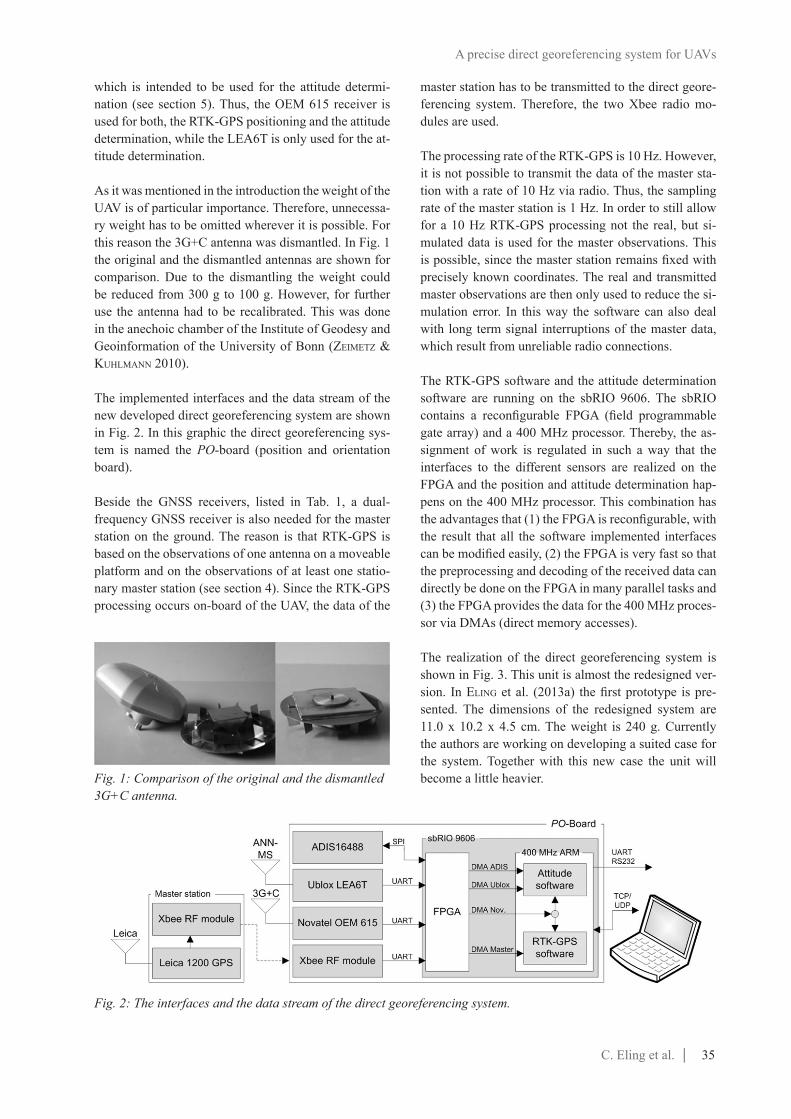
In Tab. 1 two different GNSS receivers and antennas are listed. The OEM 615 is a geodetic-grade dual-frequency GNSS receiver. In contrast to this receiver the LEA6T is considerably cheaper. The reason is that the LEA6T is a single-frequency low-cost chip. The same also applies for the antennas. The 3G+C antenna is a dual-frequency GNSS antenna, which is used in combination with the OEM 615 receiver, while the ANN-MS is a single-fre-quency GPS antenna, which provides the observations for the LEA6T receiver. Together, the 3G+C and the ANN-MS antenna form a short baseline on the UAV,
collected mapping data. That is why the development of a precise direct georeferencing system for UAVs is currently in great demand (bláha et al. 2011).
One technique, which is well suited to determine precise positions of mobile objects in a global reference frame is RTK-GPS (real time kinematic-GPS). RTK-GPS is a differential GPS (DGPS) procedure that is based on car-rier phase GNSS (Global Navigation Satellite System) observations and leads to relative positions between a master and a rover station with centimeter accuracy in real time. The challenge of developing such a system for micro- and mini-sized UAVs is to stay within the space and weight limitations of the platform. That is why only a few studies exist by now, dealing with the integration of a RTK-GPS system on micro- or mini-sized UAVs (rieke et al. 2011, stempfhuber & buchhOlz 2011).
In this contribution a new developed direct georeferen-cing system for micro- and mini-sized UAVs is presen-ted. In contrast to rieke et al. (2011) and stempfhuber & buchhOlz (2011) this new system includes an on board processing unit. Therefore, all data is directly processed on a real time computation system on the UAV with the result that there is no need for a permanent data link to a ground station, which is mostly unreliable. Further-more, the system is not only meant to determine pre-cise positions, but also to determine precise attitudes. Precise attitudes are especially needed, if the UAV is intended to fly autonomous or to be navigated precise. Furthermore, the RTK-GPS and the attitude determina-tion software are in-house developed. Thus the software can be extended and improved at any time. Due to the on board processing the precise positions and attitudes can directly be used for the navigation.
In section 2 the hardware development and the used components of the direct georeferencing system are pre-
No. Component Producer Specs # Price1 OEM 615 Novatel 120ch, dual-frequency, GNSS receiver module 1 8900 €2 ADIS16488 Analog Devices Triaxial gyroscopes, accelerometers, magnetometers & pressure
sensors, SPI1 1600 €
3 3G+C navXperience multi-frequency GNSS antenna 1 1000 €4 LEA6T Ublox 50ch, single-frequency, GPS receiver module 1 70 €5 ANN-MS Ublox single-frequency GPS antenna 1 30 €6 sbRIO-9606 National Instruments 400 MHz processor, FPGA, 256 MB DRAM 1 1200 €7 XBee Pro 868 XBee Long-range RF module, 500mW transmit power 2 70 €
8 PCB - 6-layer board, in-house designed 1 100 €9 Other components - e.g. DC/DC, HF MCX, USB-chip FTDI, GPS SAW EPCOS,... 1 70 €
Total 13110 €
Tab. 1: The main components of the direct georeferencing system.
C. Eling et al. | 35
master station has to be transmitted to the direct geore-ferencing system. Therefore, the two Xbee radio mo-dules are used.
The processing rate of the RTK-GPS is 10 Hz. However, it is not possible to transmit the data of the master sta-tion with a rate of 10 Hz via radio. Thus, the sampling rate of the master station is 1 Hz. In order to still allow for a 10 Hz RTK-GPS processing not the real, but si-mulated data is used for the master observations. This is possible, since the master station remains fixed with precisely known coordinates. The real and transmitted master observations are then only used to reduce the si-mulation error. In this way the software can also deal with long term signal interruptions of the master data, which result from unreliable radio connections.
The RTK-GPS software and the attitude determination software are running on the sbRIO 9606. The sbRIO contains a reconfigurable FPGA (field programmable gate array) and a 400 MHz processor. Thereby, the as-signment of work is regulated in such a way that the interfaces to the different sensors are realized on the FPGA and the position and attitude determination hap-pens on the 400 MHz processor. This combination has the advantages that (1) the FPGA is reconfigurable, with the result that all the software implemented interfaces can be modified easily, (2) the FPGA is very fast so that the preprocessing and decoding of the received data can directly be done on the FPGA in many parallel tasks and (3) the FPGA provides the data for the 400 MHz proces-sor via DMAs (direct memory accesses).
The realization of the direct georeferencing system is shown in Fig. 3. This unit is almost the redesigned ver-sion. In eliNg et al. (2013a) the first prototype is pre-sented. The dimensions of the redesigned system are 11.0 x 10.2 x 4.5 cm. The weight is 240 g. Currently the authors are working on developing a suited case for the system. Together with this new case the unit will become a little heavier.
which is intended to be used for the attitude determi-nation (see section 5). Thus, the OEM 615 receiver is used for both, the RTK-GPS positioning and the attitude determination, while the LEA6T is only used for the at-titude determination.
As it was mentioned in the introduction the weight of the UAV is of particular importance. Therefore, unnecessa-ry weight has to be omitted wherever it is possible. For this reason the 3G+C antenna was dismantled. In Fig. 1 the original and the dismantled antennas are shown for comparison. Due to the dismantling the weight could be reduced from 300 g to 100 g. However, for further use the antenna had to be recalibrated. This was done in the anechoic chamber of the Institute of Geodesy and Geoinformation of the University of Bonn (zeimetz & kuhlmaNN 2010).
The implemented interfaces and the data stream of the new developed direct georeferencing system are shown in Fig. 2. In this graphic the direct georeferencing sys-tem is named the PO-board (position and orientation board).
Beside the GNSS receivers, listed in Tab. 1, a dual-frequency GNSS receiver is also needed for the master station on the ground. The reason is that RTK-GPS is based on the observations of one antenna on a moveable platform and on the observations of at least one statio-nary master station (see section 4). Since the RTK-GPS processing occurs on-board of the UAV, the data of the
A precise direct georeferencing system for UAVs
Fig. 1: Comparison of the original and the dismantled 3G+C antenna.
Fig. 2: The interfaces and the data stream of the direct georeferencing system.

36 | C. Eling et al.
Proceedings of the ISPRS WG VII/5 Workshop, 09.-10.09.2013, Cologne
hardware mounted on the platform: One high-resolu-tion camera (iDS uEye UI-2280SE, 1 Hz) is intended to act as mapping sensor. Two stereo camera systems (iDS uEye UI-1221LE, 10 Hz) act as obstacle detection sensors. Furthermore, it is planned to use them for the determination of attitude changes in the future (see sec-tion 5). The additional on-board computer (Zotac Zbox nano) is needed for the on-board image processing and finally a WiFi enables the data connection of the on-board computer with a ground station. The current weight of the UAV is 4.8kg. Thus it complies with the German law formalities (weight limit: 5 kg).
4. The RTK-GPS software
As a relative positioning procedure RTK-GPS allows for the precise determination of the rover coordinates with respect to a mostly stationary master station. In Fig. 1 the basic principal of a relative GPS positioning is pre-sented. Thus, two GPS antennas are needed. In case of a
The operating system that is running on the 400 MHz pro-cessor is a real-time operating system (RTOS). The real-time processing is very important, since the system is always in motion with the result that short latencies may lead to distinct position and attitude errors. The programming of the FPGA and the 400 MHz processor is done using LabViewTM, which is a visual programming language from National InstrumentsTM. The reason for choosing Lab-ViewTM is that this programming language provides a comforta-ble programming environment for the development and admi-nistration of parallel real time tasks. Both, the RTK-GPS soft-ware and the attitude software are written in C++. The import of this software into the visual programming environment of LabViewTM was realized by dy-namic link libraries (.dll-files).
3. The UAV platform
As UAV platform the construc-tion kit “Mikrokopter Okto Xl” sold by the Company HiSystems GmbH is used (hisY-stems 2013). This platform is a multicopter containing eight rotors (octocopter). In Fig. 4 the UAV is shown to-gether with the additional hardware (Tab. 1). To be able to place the direct georeferencing system and the GNSS antennas on this platform some modifications were ne-cessary: (1) To reduce the influence of vibrations co-ming from the rotors, the original centerplates, which hold the frame together, were replaced by more stable 2 mm CFK plates. (2) Two motor side arms were turned over. This was done to be able to place the ANN-MS antenna on the top of the outer end of one of these arms. Together with the 3G+C antenna the ANN-MS antenna now forms a short baseline on the UAV. This baseline has a length of approximately 45 cm. (3) A shelf was mounted in the middle of the frame, to provide space for the on-board processing units and two lithium-polymer batteries.
The modified UAV is presented in Fig. 4. Beside the direct georeferencing system there is some additional
Fig. 3: The direct georeferencing system seen from the top-view.
Fig. 4: The modified UAV platform together with the on-board georeferencing and mapping sensors.

C. Eling et al. | 37
ambiguity resolution process should be fast and robust at the same time.
The direct georeferencing system that is presented in this contribution consists of an in-house developed RTK-GPS software. This software was developed to allow for a fast, if not instantaneous, ambiguity reso-lution. Further advantages of using an own RTK-GPS software are that (1) the software can be used with any kind of receiver (low-cost, consumer-grade or geode-tic grade), (2) the software can be modified for special uses and (3) the observations of additional sensors (e.g. inertial sensors) can be used to improve the ambiguity resolution within a tightly coupled approach.
The principal calculation steps of the RTK-GPS soft-ware are shown in Fig. 6. Hence, the ambiguity resolu-tion occurs in 3 steps: (1) float solution, (2) ambiguity search and (3) ratio test. In the float solution the ambigu-ities are estimated in an extended Kalman filter. In this filter carrier phases and code pseudo ranges are used as observations. The reason for using the carriers and the code pseudo ranges is that every carrier phase observati-on necessitates one ambiguity parameter. Since also the position parameters have to be estimated, the extended
UAV positioning one is mounted on the UAV (rover an-tenna) and one remains on the ground (master antenna). Generally, GPS provides carrier phases and code pseudo ranges. Since carrier phase ranges are far more accurate than code pseudo ranges, RTK-GPS is mainly based on carrier phase observations. These carrier phase ranges are symbolized by the sine-shaped waves in Fig. 5.
The advantage of a relative positioning is that systema-tic observation errors are significantly reduced or even eliminated by a single- and double-differencing of the observations (e.g. hOfmaNN-WelleNhOf et al. 2008). A single-difference is the difference of the signal of one satellite, which is received at both antennas (master and rover station). Such a single-difference is shown in Fig. 5. Therein, the observed carrier phase single-difference is referred to as the fractional part. Due to the single-differencing the satellite clock bias, the satellite orbit errors and the atmosphere effects (ionosphere and tro-posphere) can be reduced significantly. After the sin-gle-differencing usually a double-differencing follows. Double-differences can be obtained by differencing the single-differences of different satellites. This is done to also eliminate receiver errors, such as the receiver clock biases.
For the determination of the baseline parameters (∆x, ∆y, ∆z), which represent the rela-tive position of the rover with respect to the master, not only the double-differenced fractio-nal part, but also the double-dif-ferenced integer part has to be known. This integer part inclu-des the unknown number of in-teger cycles of the double diffe-rences. While the fractional part can be observed, the integer part has to be resolved in the so cal-led ambiguity resolution. Thus, the ambiguity resolution is the key to RTK-GPS positioning.
Especially in kinematic appli-cations the rapidity of the ambi-guity resolution is of particular importance. The reason for this is that obstacles like street can-yons, bridges or vegetation lead to frequent losses of lock of the GPS signals. Since every loss of lock necessitates a re-initia-lization of the ambiguities the
Fig. 5: Basic principal of a single-difference RTK-GPS measurement.
Fig. 6: Flow diagram of the RTK-GPS software.
A precise direct georeferencing system for UAVs

38 | C. Eling et al.
Proceedings of the ISPRS WG VII/5 Workshop, 09.-10.09.2013, Cologne
of the attitude software it is planned to realize these le-vels of quality step-by step.
As the first realization the attitude determination cur-rently occurs in a quaternion extended Kalman filter and is based on the observations of the accelerometers, gyroscopes and the magnetometer only. In this sen-sor combination the magnetometer is the only sensor providing information for the yaw determination. Ho-wever, it is well known that the magnetic field sensors are distorted by hard iron and soft iron effects. While hard iron distortions arise from permanent magnets and magnetized iron or steel on the compass platform, soft iron distortion arises from any magnetically soft mate-rial surrounding the compass (carusO 2000). Certain-ly, by means of a sensor calibration, the effect of the magnetic distortion can be reduced. Nevertheless, the magnetometer doesn’t allow for an attitude determina-tion with the intended accuracies of σ<1deg. That is the reason, why in the second level of quality an on-board GPS baseline is intended to be integrated in the attitude determination in the future.
By means of the on-board GPS baseline the yaw angle and one inclination angle (roll or pitch) of the UAV can directly be determined driftless with high accuracies (σ<0.5deg) (eliNg et al. 2013b). Basically, the proces-sing of GPS attitudes happens in a similar way as the RTK-GPS determination. However, the on-board GPS baseline includes one single-frequency GPS receiver (u-blox LEA6T) with the result that only single-frequency GPS observations can be used for the attitude determi-nation. For single-frequency GPS processing the am-biguity resolution is much more difficult compared to dual-frequency GPS processing so that the time to fix the ambiguities of single-frequency GPS data generally takes a few minutes (ODijk et al. 2007). For kinematic applications this is considerably too much time. Thus, to overcome this problem the authors are currently working on a combination of the accelerometers, gyro-scopes, magnetometers and the GPS baseline.
In this combination the solution from the first realization step is used as approximate solution to limit the size of the ambiguity search space in the float solution. As a re-sult the ambiguity resolution is getting faster and more reliable. Once the ambiguities are fixed the observations of the accelerometers, gyroscopes and the GPS baseline are fused in a quaternion extended Kalman filter.
In the third level of quality the stereo cameras will also be integrated in the attitude determination. Therefore, an incremental bundle adjustment has to be determined on the on-board computer of the UAV during the flight
Kalman filter could not be solved within one epoch, if only the carrier phases would be used. The result of the float solution is a vector containing the real valued am-biguities and a covariance matrix.
As it was mentioned above, the double-difference am-biguities are integers by nature. Thus, the real valued ambiguities resulting from the float solution have to be fixed to integer values. This fixing happens in the ambi-guity search with the MLAMBDA method (chaNg et al. 2005). In comparison to the original LAMBDA method (teuNisseN 1995) this algorithm is a little faster, if many observations are available. Basically, the MLAMBDA method as well as the LAMBDA method are based on a decorrelation and a sequential-conditioned search over an ellipsoidal region.
After the search process a decision must be made, if the integer ambiguities from the ambiguity search step are reliable or not. Therefore, the squared norm of the resi-duals of the best set of ambiguities (R1) and the squared norm of the residuals of the second best set of ambigu-ities (R2) are compared in the ratio test (VerhageN & teuNisseN 2006). Only if the quotient R2/R1 satisfies a threshold of 3 the ambiguities are fixed to integer va-lues. In case the ratio test fails, the RTK-GPS software only provides a float-solution, which leads to decime-ter accuracies. Normally, the time to fix the ambiguities takes a few epochs, but often the ambiguities can alrea-dy be fixed within the first epoch. Once the ambiguities could be resolved successfully, they can be hold fixed, as long as no signal interruption or cycle slip occurs. In contrast to the float solution only the carrier phases are used as observations in the fixed solution.
5. The attitude determination software
The attitude determination aims for computing the three orientation angles roll, pitch and yaw of the UAV. For this purpose, observations of different sensors can be used: accelerometers, gyroscopes, a magnetometer, ste-reo cameras and a GPS baseline. The accelerometers al-low for the determination of the roll and the pitch angles by relating the body orientation to the gravity vector. The gyroscopes measure the angular rates of the body frame with respect to an inertial coordinate frame. The magnetometer enables the heading determination of the UAV by measuring the earth magnetic field vector and the stereo cameras observe the changes of the camera orientations with respect to distinctive pixels. Using the presented direct georeferencing system, generally three levels of quality, by which the attitudes of the UAV can be determined are possible. In the development process

C. Eling et al. | 39
a static part an enlarged view of the height time series is shown in Fig. 9. In this figure the precision of the heights becomes apparent, since the results only fluctu-ate in the range of 1-2 cm.
The recorded attitudes are shown in Fig. 10. Thus, the roll and the pitch vary in a range of +/- 10 deg duri-ng a normal flight. As it was mentioned in section 5, currently only the first realization step of the attitude determination software using the magnetometers, the
(schNeiDer et al. 2013). Since this processing is not real-time capable a time latency has to be considered by integrating the resulting attitude changes from the stereo cameras in the attitude Kalman filter.
The fusion of so many different sensors is very important to incre-ase the robustness of the attitude determination. Especially in chal-lenging environments the sensor combination covers all disadvan-tages of the single attitude sensors.
6. Resultsofafieldtest
The functionality of the newly developed direct georeferencing system has already been tested in many flights. In this chapter the re-sults of one of this test flights will be presented. The flight was per-formed on an open field in Bonn, Germany. The positions and atti-tudes, which were determined in real-time, were recorded on a USB device on the direct georeferen-cing unit. In Fig. 7 the RTK-GPS positions of the flown track are shown. During this test the UAV was intended to fly automatically along defined waypoints. For this waypoint flight the low-cost GPS module supplied by the manufac-turer of the UAV was used. Since this GPS module is not very pre-cise the flown track is not very straightforward, too. To give an impression how precise the RTK-GPS positions are, an enlarged view of a small part of the track is also shown in Fig. 7. The resulting accuracies of the determined positions are in the range of 0.5-2 cm for the north and the east components and 1-3 cm for the height component. For the future it is planned to commit the RTK-GPS positions to the flight control of the UAV to also enable a precise navigation of the vehicle in a waypoint flight.
The relative heights between the master station and the UAV are presented in Fig. 8. In the beginning and in the end of the test, the UAV stood on the ground. For such
Fig. 7: Tracked RTK-GPS positions during a test-flight with the UAV.
Fig. 8: The heights that were tracked during the flight.
Fig. 9: Enlarged view of the marked section from the time series of the tracked heights shown in Fig. 8.
A precise direct georeferencing system for UAVs

40 | C. Eling et al.
Proceedings of the ISPRS WG VII/5 Workshop, 09.-10.09.2013, Cologne
Referencesblàha, m., eiseNbeiss, h., grimm, D. & limpach, p.
(2011): Direct georeferencing of UAVs.- In: Pro-ceedings of the UAV-g 2011 conference, Zurich, Switzerland.
carusO, m.j. (2000): Applications of magnetic field sensors for low-cost compass systems.- In: IEEE Position, Location and Navigation Symposium, 177-184.
chaNg, X.-W., YaNg, X. & zhOu, t. (2005): MLAMB-DA: A modified LAMBDA method for integer least squares estimation. - J Geod, 79: 552-565.
D’Oleire-OltmaNNs, s., marzOlff, i., peter, k.D. & ries, j.b. (2012): Unmanned aerial vehicle (UAV) for monitoring soil erosion in morocco. - Remote Sensing, 4: 3390-3416.
eliNg, c., kliNgbeil, l., WielaND, l. & kuhlmaNN, h. (2013a): A precise position and attitude deter-mination system for lightweight unmanned aerial vehicles. Accepted for publication in: UAV-g 2013
gyroscopes and the accelerometers is implemented on the direct geo-referencing system. The accuracy of this sensor combination is ap-proximately 2 deg, where the ma-gnetometer is the limiting factor.
7. Conclusions and outlook
In this contribution a newly deve-loped direct georeferencing sys-tem has been presented. The sys-tem is designed to be applicable on micro- and mini-sized UAVs and to provide precise positions and attitudes in real time. Due to the combination of GPS, an IMU and cameras it allows for a multi sensor fusion with the advantage that gaps of single sensors can be bridged.
It could be shown that the system is almost applicable on UAVs. Currently an in-house developed RTK-GPS software and a first re-alization of algorithms for an atti-tude determination are running on the system with a rate of >10 Hz. The resulting accuracies are 1-5 cm for the positions and 1-3 deg for the attitudes.
Even though the hardware development is mostly com-pleted there is still a lot of software extension possible. Like it was mentioned in section 3 and 4 the authors are currently working on the integration of a single-frequency GPS baseline in the attitude determination. Furthermore, the IMU is also intended to be used to improve the ambiguity resolution in the RTK-GPS de-termination. Finally, the stereo camera systems will be integrated in the position and attitude determination in the future.
Acknowledgement
The presented developments are part of the project “Mapping on Demand”, which is supported by the DFG (Deutsche Forschungsgemeinschaft) under the project number FOR 1505. The authors like to express their gratitude for that.
Fig. 10: The determined attitudes of the test flight.

C. Eling et al. | 41
Control Dynam, 29(4), 981-991.XiaNg, H. & tiaN, L. (2011): Development of a low-
cost agriculture remote sensing system based on an autonomous unmanned aerial vehicle (UAV). - Bio-systems Engineering, 108: 174-190.
YOO, c. & ahN, i. (2003): Low cost GPS/INS sensor fusion system for UAV navigation.- In: Proceedings of the 22nd Digital Avonics Systems Conference, 2, 8.A.1-1 - 8.A.1-9.
zeimetz, p. & kuhlmaNN, h. (2010): Validation of the labroratory calibration of geodetic antennae based gps measurements.- In: FIG Working Week, Sydney, Australia.
conference, Rostock, Germany.eliNg, c., zeimetz, p. & kuhlmaNN, h. (2013b): Devel-
opment of an instantaneous GNSS/MEMS attitude determination system. - GPS Solut, 17: 129-138.
eiseNbeiss, h., lambers, k. & sauerbier, m. (2005): Photogrammetric recording of the archaeological site of Pinchango Alto (Palpa, Peru) using a mini he-licopter (UAV).- In: figuireDO a. & VelhO g. (eds.): The World is in Your Eyes – Proceedings of the 33rd CAA Conference.
hisYstems (2013): HiSystems GmbH, the mikrokopter shop: www.mikrokontroller.com. 2014-01-04.
hOfmaNN-WelleNhOf, b., lichteNegger, h. & Wasle, e. (2008): GNSS Global Navigation Satellite Sys-tems.- New York.
merz, t. & keNDOul, f. (2011): Beyond visual range obstacle avoidance and infrastructure inspection by an autonomous helicopter.- In: Proceedings of the IEEE/RSJ International Conference on Intelligent Robots and Systems, IROS 2011, San Francisco, USA.
Nagai, m., cheN, t., shibasaki, r., kumagai, h. & ahmeD, a. (2009): UAV-borne 3-D mapping system by multisensor integration. - IEEE T Geosci Re-mote, 47(3): 701-708.
ODijk, D., traugOtt, j., sachs, g., mONteNbruck, O. & tiberius, c. (2007): Two precision GPS approaches applied to kinematic raw measurements of miniatur-izes L1 receivers.- In: Proceedings of the 20th In-ternational Technical Meeting of the Satellite Divi-sion of the Institute of Navigation ION GNSS 2007, 827-838.
rieke, m., fOerster, t., geipel, j. & priNz, t. (2011): High-precision positioning and real-time data pro-cessing of UAV-systems.- In: UAV-g conference 2011, Zurich, Switzerland.
schNeiDer, j., läbe, t. & förstNer, W. (2013): Incre-mental Real-time Bundle Adjustment for Multi-camera Systems with Points at Infinity. Accepted for publication in: UAV-g 2013 conference, Rostock, Germany
ŠkalOuD, j. (1999): Optimizing Georeferencing of Air-borne Survey Systems by INS/DGPS.- PhD thesis, University of Calgary.
stempfhuber, W. & buchhOlz, m. (2011): A precise, low-cost RTK GNSS System for UAV Applica-tions.- In ISPRS Zurich 2011 Workshop, Zurich, Switzerland, 289-293.
teuNisseN, P.J.G. (1995): The least-squares ambiguity decorrelation adjustment: a method for fast ambigu-ity estimation. - J Geod, 70: 65-82.
VerhageN, S. & teuNisseN, P.J.G. (2006): New Global Navigation Satellite System Ambiguity Resolution Method Compared to Existing Approaches. - J Guid
Contact information Christian Eling
University of Bonn Institute of Geodesy and Geoinformation
Nussallee 17 D-53115 Bonn
Germany [email protected]
+49 (0)228 73 3565
A precise direct georeferencing system for UAVs