a principled approach to managing routingjrex/thesis/yi-wang-thesis.pdf · a principled approach to...
TRANSCRIPT
A PRINCIPLED APPROACH TOMANAGING ROUTING
IN LARGE ISP NETWORKS
Y I WANG
A D ISSERTATION
PRESENTED TO THEFACULTY
OF PRINCETON UNIVERSITY
IN CANDIDACY FOR THE DEGREE
OF DOCTOR OFPHILOSOPHY
RECOMMENDED FORACCEPTANCE
BY THE DEPARTMENT OF
COMPUTER SCIENCE
ADVISOR: PROFESSORJENNIFER REXFORD
JUNE 2009

c© Copyright by Yi Wang, 2009. All rights reserved.

Abstract
Internet Service Providers (ISPs) are the core building blocks of the Internet, and play a crucial
role in keeping the Internet well-connected and stable, as well as providing services that meet the
needs of other ASes (and their users). As a result, an ISP plays different roles in its operation: (1)
as part of the Internet, an ISP is expected to help keep the global network stable; (2) when interact-
ing with neighboring networks, an ISP faces diverse requirements from different neighbors about
the kinds of routes they prefer; and (3) internally, an ISP needs to maintain and upgrade its own
network periodically, and wants avoid disruptions during those operations as much as possible.
As the Internet has become an integral part of the world’s communications infrastructure, today’s
ISPs face a number of routing management challenges at thesedifferent scopes, which include: (i)
maintaining the stability of theglobal Internet while meeting the increasingly demands for pro-
viding diverse routes from its customers, (ii) supporting more flexible routing policy configuration
in bilateral contractual relationships with itsneighbors, and (iii) making network maintenance and
other network management operations in theirownnetworks easier and less disruptive to routing
protocols and data traffic.
This dissertation takes a principled approach to addressing these challenges. We propose three
abstractions that guide the design and implementation of our system solutions. First, we propose
the abstraction of a “neighbor-specific route selection problem” and a corresponding “Neighbor-
Specific BGP” (NS-BGP) model that capture the requirement ofcustomized route selection for
different neighbors. Since one ISP’s route selection decisions could cause the global Internet to
become unstable, we prove the conditions under which the Internet is guaranteed to remain stable
even if individual ISPs make the transition to this more flexible route-selection model. Second, we
model policy configuration as a decision problem, which offers an abstraction that supports the rec-
onciliation of multiple objectives. Guided by this abstraction and the Analytic Hierarchy Process, a
decision-theoretic technique for balancing conflicting objectives, we designed and implemented a
prototype of an extensible routing control platform (Morpheus) that enables an ISP to select routes
iii

for different neighbors individually and make flexible trade-offs among policy objectives through
a simple and intuitive configuration interface. Finally, wepropose the abstraction of the separation
between “physical” and “logical” configurations of routers, which leads us to the design and proto-
type implementation of “virtual router migration” (VROOM), a new, generic technique to simplify
and enable a broad range of network management tasks, from planned maintenance to reducing
power consumption. Collectively, the contributions of thedissertation provide simple system solu-
tions for an ISP to autonomously manage its routing more flexibly and effectively without affecting
global routing stability.
iv

Acknowledgments
I am extremely fortunate to have Jennifer Rexford as my advisor, working with her has made my
four years at Princeton one of the best times of my life. I cannot remember how many times I
told myself, my family and friends that my advisor is the bestimaginable and I could not believe
how lucky I am. I want to thank Jennifer for being both “hands off” and “hands on”: giving me
enough freedom and encouraging me to pursue problems I foundmost interesting, yet providing
inspirational guidance and detailed help whenever I need them, e.g., bouncing off new ideas, deep
discussion of research approaches, learning how to improvepaper writing and give better presen-
tation, etc. Her sharp intellect and solid expertise made the discussions I had with her some of the
most enlightening and memorable moments of my graduate career, without which this dissertation
would not have been possible. I am also very grateful for Jennifer’s encouragement and support
for me to present my work at various conferences, universities and research institutions, and to
obtain broader experience through internships. Thanks to these wonderful experiences, I built con-
fidence from presenting to and discussing with many brightest minds and experts in the field, got
invaluable feedback for my work, deepened understanding ofthe academic and industrial research
landscape, and made many good friends. Besides being a fantastic advisor, Jennifer continually
amazed me with her thoughtfulness and genuine kindness to everyone she met, and her humility.
She will be role model for me for years to come.
I am also very lucky to have worked extensively with Kobus vander Merwe. As mentor of my
internship at AT&T Research, Kobus shared my passion for practical problems. His openness to
new ideas and humor made him a fun person to work with. As paperco-author, his provocative
thinking and rigorous attitude set an example of a true scholar that I strived to follow. As reader
of my dissertation, he read this dissertation with vigilance, and his detailed suggestions helped me
strengthen many aspects of this dissertation.
I would like to thank Mike Freedman, Larry Peterson and Ed Felten for serving on my thesis
committee, and giving me valuable feedback on my work.
v

I owe a special thank you to Ioannis Avramopoulos, Eric Keller, Brian Biskeborn and Michael
Schapira for their invaluable help and contribution to the papers we co-authored, which constitute
the major chapters of this dissertation. Collaborating with them has been a truly pleasant and inspi-
rational experience. I would also like to thank Nick Feamster, Matthew Caeser, Aman Shaikh, Tim
Griffin, David Walker, Murtaza Motiwala, Vytautas Valancius, Dan Wendlandt, Ricardo Oliveira,
Mohit Lad and many others for their valuable feedback and help to my research over the years.
My research was supported by the National Science Foundation, Homeland Security Advanced
Research Projects Agency/ARO and Princeton. Many thanks toall for making this research possi-
ble.
My life at Princeton would have been unimaginable without anamazing group of friends.
As part of the Cabernet group, I benefited tremendously from its members’ diverse interests and
expertise, in research and beyond. Changhoon Kim was my guruof enterprise networking and
gave me great advice and support for my research and beyond incountless discussions. He also
introduced me to mountain biking, together with Mark McCann. Haakon Ringberg was a reliable
source of great comments and suggestions for a lot of things:my research papers and presentations,
wines, good restaurants, just to name a few. I had a great timeliving, running, cooking, hiking,
and BBQ-ing together with Chang and Haakon in the summer of 2007, when we were interning at
AT&T Research. I will miss Sharon Goldberg’s right-on criticism of my presentations followed by
constructive comments. I would also like to thank Jiayue He,Rui Zhang-Shen, Eric Keller, Minlan
Yu, Yaping Zhu, Elliott Karpilovsky, Martin Suchara, Wenjie Jiang, Pete Hummon, Alex Fabrikant
for fun conversations and their invaluable feedback for my work over the years.
I would also like to thank my friends from the rest of the Computer Science Department (Zafer
Barutcuoglu, Chris Bienia, Jordan Boyd-Garber, Joe Calandrino, Tony Capra, Melissa Carroll,
Will Clarkson, Forrester Cole, Wei Dong, Ariel Feldman, Rebecca Fiebrink, Shirley Gaw, Michael
Golightly, William Josephson, Wyatt Lloyd, Xiaojuan Ma, KyoungSoo Park, Lindsey Poole, Sid
Sen, David Shue, Umar Syed, Jeff Terrace, Mike Wawrzoniak, Qian Xi, Harlan Yu, Bill Zeller,
vi

Yun Zhang) for introducing me to new research areas and making me feel home in the depart-
ment. I thank my friends from the Princeton Graduate StudentGovernment and the GSG Events
Board (Kostas Aisopos, Raja Chahal, Jeff Dwoskin, Christina Holtholm, Manos Koukoumidis,
Jenna Losh, Olivia Matel, Marina Paul, Lisa Schreyer, Ashley Thrall, Anne Twitty), the Prince-
ton Graduate Engineering Council (Theresa Cho, Brian Figura, Brian Ellis, Raghuveer Vinukollu,
Vijay Krishnamurthy), the Princeton Badminton Club (Shelley Chan, Kevin Fan, Teck Hsien Ho,
Chern Han Lim, Richard She, Lova Sun, Shu Haur Tang, Aldi Wahyudi), and too many others to
mention, for making my life outside research fun and enjoyable.
I am grateful to my host family Dotty Westgate for introducing me to American culture through
Christmas and Super-bowl parties and delightful conversations. I thank Jingrong Huang and Da
Teng for helping me settle down when I first arrived at Princeton. I am also indebted to Natasha
Haase for her invaluable help to my job search. Special thanks to Melissa Lawson for her help
throughout my study at Princeton, specially during the graduation process.
I thank my parents, Zhiying Sun and Baimao Wang, for their enduring love, belief and encour-
agement, without which this accomplishment would have beenimpossible.
Above all, I would like to thank my wife, Jing Cao, for her love, support, and unwavering faith
in me, and for bringing me joy and optimism throughout my Ph.D. I dedicate this dissertation to
her.
vii

Contents
Abstract . . . . . . . . . . . . . . . . . . . . . . . . . . . . . . . . . . . . . . . . . . .iii
1 Introduction 4
1.1 An Overview of ISP Routing Management . . . . . . . . . . . . . . . .. . . . . . 6
1.1.1 An ISP’s Role in The Global Internet . . . . . . . . . . . . . . . .. . . . 6
1.1.2 An ISP’s Interaction With Its Neighbors . . . . . . . . . . . .. . . . . . . 7
1.1.3 An ISP’s Responsibility in Managing Its Own Network . .. . . . . . . . . 8
1.2 Challenges in ISP Routing Management . . . . . . . . . . . . . . . .. . . . . . . 9
1.2.1 Many Useful Routing Policies Cannot Be Realized . . . . .. . . . . . . . 9
1.2.2 Many Policies Which Are Realizable Are Hard To Configure . . . . . . . . 11
1.2.3 Many Unnecessary Routing (Re)configurations Cause Disruption . . . . . 12
1.3 Contributions . . . . . . . . . . . . . . . . . . . . . . . . . . . . . . . . . . .. . 13
1.3.1 A Customized Route Selection Model With Improved Stability . . . . . . . 13
1.3.2 A System for Flexible Routing Configuration With Intuitive Interface . . . 14
1.3.3 A Technique for Managing Network Changes Without Disruption . . . . . 14
2 Neighbor-Specific BGP (NS-BGP): More Flexible Routing Policies While Improving
Global Stability 16
2.1 Introduction . . . . . . . . . . . . . . . . . . . . . . . . . . . . . . . . . . . .. . 16
2.1.1 A Case for Neighbor-Specific BGP . . . . . . . . . . . . . . . . . . .. . 17
viii

2.1.2 Stability Concerns of Greater Flexibility . . . . . . . . .. . . . . . . . . . 19
2.1.3 Relaxing the “Prefer Customer” Condition . . . . . . . . . .. . . . . . . 20
2.2 Neighbor-Specific BGP (NS-BGP) . . . . . . . . . . . . . . . . . . . . .. . . . . 22
2.2.1 Preliminaries . . . . . . . . . . . . . . . . . . . . . . . . . . . . . . . . .22
2.2.2 Neighbor-Specific Route Selection Model . . . . . . . . . . .. . . . . . . 23
2.2.3 Stable Path Assignment . . . . . . . . . . . . . . . . . . . . . . . . . .. 25
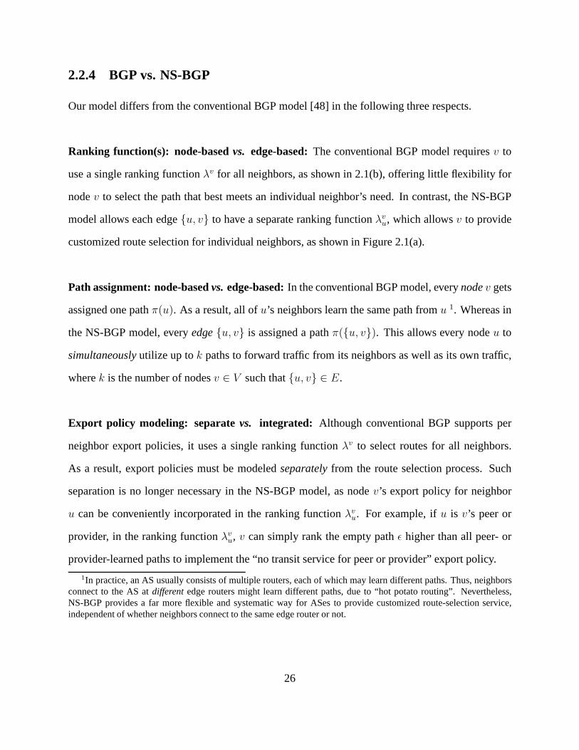
2.2.4 BGP vs. NS-BGP . . . . . . . . . . . . . . . . . . . . . . . . . . . . . . . 26
2.3 Sufficient Conditions for NS-BGP Stability . . . . . . . . . . .. . . . . . . . . . 27
2.3.1 Formal Definition of NS-BGP Safety . . . . . . . . . . . . . . . . .. . . 27
2.3.2 Iterated Dominance . . . . . . . . . . . . . . . . . . . . . . . . . . . . .. 28
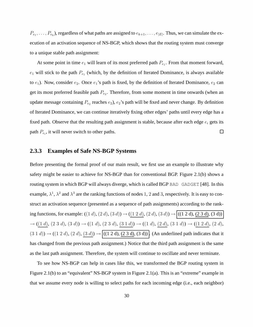
2.3.3 Examples of Safe NS-BGP Systems . . . . . . . . . . . . . . . . . . .. . 30
2.3.4 Safety Conditions for NS-BGP . . . . . . . . . . . . . . . . . . . . .. . . 32
2.3.5 Tightness of the Safety Conditions . . . . . . . . . . . . . . . .. . . . . . 35
2.4 Practical Implications . . . . . . . . . . . . . . . . . . . . . . . . . . .. . . . . . 37
2.4.1 Safe Under Topology Changes . . . . . . . . . . . . . . . . . . . . . .. . 38
2.4.2 Safe in Partial Deployment . . . . . . . . . . . . . . . . . . . . . . .. . . 38
2.4.3 Safer With Backup Relationship . . . . . . . . . . . . . . . . . . .. . . . 39
2.4.4 Preventing Instability in Internal BGP . . . . . . . . . . . .. . . . . . . . 42
2.5 Deployment Issues . . . . . . . . . . . . . . . . . . . . . . . . . . . . . . . .. . 43
2.5.1 Neighbor-Specific Forwarding . . . . . . . . . . . . . . . . . . . .. . . . 44
2.5.2 Route Dissemination Within an AS . . . . . . . . . . . . . . . . . .. . . 45
2.5.3 Control Over Customized Selection . . . . . . . . . . . . . . . .. . . . . 46
2.6 NS-BGP and Incentives . . . . . . . . . . . . . . . . . . . . . . . . . . . . .. . . 48
2.6.1 Background: BGP is Not Incentive-Compatible . . . . . . .. . . . . . . . 49
2.6.2 NS-BGP is Not Incentive-Compatible . . . . . . . . . . . . . . .. . . . . 50
2.6.3 Not Being Incentive-Compatible Does Not Affect Stability . . . . . . . . . 50
ix

2.7 Related Work . . . . . . . . . . . . . . . . . . . . . . . . . . . . . . . . . . . . .51
2.8 Summary . . . . . . . . . . . . . . . . . . . . . . . . . . . . . . . . . . . . . . . 52
3 Morpheus: Making Flexible Policies Easier to Configure 53
3.1 Introduction . . . . . . . . . . . . . . . . . . . . . . . . . . . . . . . . . . . .. . 53
3.2 Routing Architecture . . . . . . . . . . . . . . . . . . . . . . . . . . . . .. . . . 57
3.2.1 Complete Visibility of BGP Routes . . . . . . . . . . . . . . . . .. . . . 57
3.2.2 Flexible Route Assignment . . . . . . . . . . . . . . . . . . . . . . .. . . 59
3.2.3 Consistent Packet Forwarding . . . . . . . . . . . . . . . . . . . .. . . . 59
3.3 Server Software Architecture . . . . . . . . . . . . . . . . . . . . . .. . . . . . . 61
3.3.1 Multiple Independent Policy Classifiers . . . . . . . . . . .. . . . . . . . 61
3.3.2 Multiple Weighted-Sum Decision Processes . . . . . . . . .. . . . . . . . 64
3.4 AHP-Based Policy Configurations . . . . . . . . . . . . . . . . . . . .. . . . . . 69
3.4.1 The Offline AHP Configuration Process . . . . . . . . . . . . . . .. . . . 69
3.4.2 Adapting AHP to Work Online . . . . . . . . . . . . . . . . . . . . . . .. 71
3.4.3 A Policy Configuration Example . . . . . . . . . . . . . . . . . . . .. . . 72
3.5 Implementation . . . . . . . . . . . . . . . . . . . . . . . . . . . . . . . . . .. . 75
3.5.1 Changes to XORP . . . . . . . . . . . . . . . . . . . . . . . . . . . . . . 75
3.5.2 Policy Classifiers . . . . . . . . . . . . . . . . . . . . . . . . . . . . . .. 76
3.5.3 Decision Processes . . . . . . . . . . . . . . . . . . . . . . . . . . . . .. 77
3.6 Implementation and Evaluation . . . . . . . . . . . . . . . . . . . . .. . . . . . . 78
3.6.1 Evaluation Testbed . . . . . . . . . . . . . . . . . . . . . . . . . . . . .. 79
3.6.2 Evaluation of Processing Time . . . . . . . . . . . . . . . . . . . .. . . . 79
3.6.3 Throughput . . . . . . . . . . . . . . . . . . . . . . . . . . . . . . . . . . 83
3.6.4 Memory Requirement . . . . . . . . . . . . . . . . . . . . . . . . . . . . 84
3.7 Related Work . . . . . . . . . . . . . . . . . . . . . . . . . . . . . . . . . . . . .85
x
3.8 Summary . . . . . . . . . . . . . . . . . . . . . . . . . . . . . . . . . . . . . . . 86
4 VROOM: Live (Virtual) Router Migration as a Network-Manag ement Primitive 87
4.1 Introduction . . . . . . . . . . . . . . . . . . . . . . . . . . . . . . . . . . . .. . 87
4.2 Background: Flexible Link Migration . . . . . . . . . . . . . . . .. . . . . . . . 90
4.3 Network Management Tasks . . . . . . . . . . . . . . . . . . . . . . . . . .. . . 93
4.3.1 Planned Maintenance . . . . . . . . . . . . . . . . . . . . . . . . . . . .. 93
4.3.2 Service Deployment and Evolution . . . . . . . . . . . . . . . . .. . . . 94
4.3.3 Power Savings . . . . . . . . . . . . . . . . . . . . . . . . . . . . . . . . 95
4.4 VROOM Architecture . . . . . . . . . . . . . . . . . . . . . . . . . . . . . . .. . 96
4.4.1 Making Virtual Routers Migratable . . . . . . . . . . . . . . . .. . . . . 96
4.4.2 Virtual Router Migration Process . . . . . . . . . . . . . . . . .. . . . . 99
4.5 Prototype Implementation . . . . . . . . . . . . . . . . . . . . . . . . .. . . . . 103
4.5.1 Enabling Virtual Router Migration . . . . . . . . . . . . . . . .. . . . . . 103
4.5.2 Realizing Virtual Router Migration . . . . . . . . . . . . . . .. . . . . . 107
4.6 Evaluation . . . . . . . . . . . . . . . . . . . . . . . . . . . . . . . . . . . . . .. 108
4.6.1 Methodology . . . . . . . . . . . . . . . . . . . . . . . . . . . . . . . . . 109
4.6.2 Performance of Migration Steps . . . . . . . . . . . . . . . . . . .. . . . 110
4.6.3 Data Plane Impact . . . . . . . . . . . . . . . . . . . . . . . . . . . . . . 112
4.6.4 Control Plane Impact . . . . . . . . . . . . . . . . . . . . . . . . . . . .. 115
4.7 Migration Scheduling . . . . . . . . . . . . . . . . . . . . . . . . . . . . .. . . . 117
4.8 Related Work . . . . . . . . . . . . . . . . . . . . . . . . . . . . . . . . . . . . .118
4.9 Summary . . . . . . . . . . . . . . . . . . . . . . . . . . . . . . . . . . . . . . . 119
5 Conclusion 121
5.1 Summary of Contributions . . . . . . . . . . . . . . . . . . . . . . . . . .. . . . 122
5.2 The Synergy of Deploying Morpheus and VROOM Together . . .. . . . . . . . . 123
xi

5.3 Open Issues and Future Work . . . . . . . . . . . . . . . . . . . . . . . . .. . . . 124
5.3.1 Using Morpheus and VROOM to Handle Traffic Engineering. . . . . . . 124
5.3.2 The Evolving Functions of Routers . . . . . . . . . . . . . . . . .. . . . 125
5.3.3 Dynamics of NS-BGP . . . . . . . . . . . . . . . . . . . . . . . . . . . . 125
5.4 Concluding Remarks . . . . . . . . . . . . . . . . . . . . . . . . . . . . . . .. . 126
xii
List of Figures
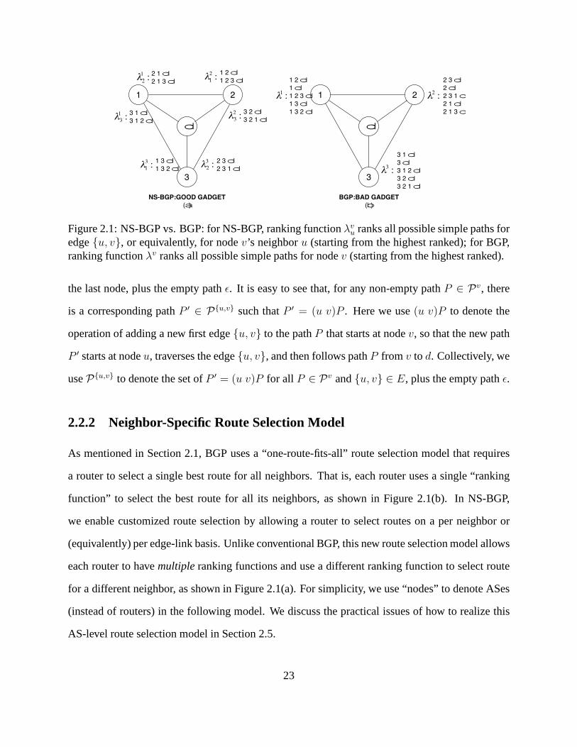
2.1 NS-BGP vs. BGP: for NS-BGP, ranking functionλvu ranks all possible simple
paths for edge{u, v}, or equivalently, for nodev’s neighboru (starting from the
highest ranked); for BGP, ranking functionλv ranks all possible simple paths for
nodev (starting from the highest ranked). . . . . . . . . . . . . . . . . . . . .. . 23
2.2 Why NS-BGP does not need the “preference condition” and can safely allow nodes
to choose any exportable routes: the dotted arrows denote the stable path assign-
ment, in which every nodei (i = 1, 2, 3) makes the direct path{i, d} available to
its clockwise neighbor while using a different path itself.. . . . . . . . . . . . . . 31
2.3 Tightness of the NS-BGP safety conditions . . . . . . . . . . . .. . . . . . . . . 35
2.4 A BGP Wedgie: AS2 will not switch back to path(2 3 d) after the primary link
{3, d} is restored from a failure. . . . . . . . . . . . . . . . . . . . . . . . . . . . 41
2.5 An NS-BGP Wedgie: ASes 2 and 3 will not switch back to the path through the
primary link{5, d} after it is restored from a failure. . . . . . . . . . . . . . . . . . 42
2.6 AS Z has multiple interdomain routes for destination D . .. . . . . . . . . . . . . 45
2.7 A system that is not incentive compatible in both BGP and NS-BGP . . . . . . . . 49
3.1 Morpheus routing architecture: Morpheus servers peer with neighboring domains
via multi-hop BGP sessions; edge routers direct interdomain traffic through tunnels. 58
3.2 Morpheus’ BGP route selection process, which includes route classification and
best route selection. . . . . . . . . . . . . . . . . . . . . . . . . . . . . . . . .. . 61
1

3.3 Each decision process consists of a set of mapping functions of the policy ob-
jectives and a score function. Different decision processes are configured with
different mapping functions and/or score functions to realize different policies. . . 66
3.4 The decision hierarchy of AHP. . . . . . . . . . . . . . . . . . . . . . .. . . . . . 70
3.5 Example of a decision hierarchy. . . . . . . . . . . . . . . . . . . . .. . . . . . . 71
3.6 The AHP hierarchy of an example routing policy. . . . . . . . .. . . . . . . . . . 73
3.7 Morpheus prototype implemented as an extension to XORP .. . . . . . . . . . . . 75
3.8 Classification time: time taken by the classifiers to tag aroute. . . . . . . . . . . . 80
3.9 Decision time: time taken by the mapping functions and the score function, and
the total decision time (1 route per prefix) . . . . . . . . . . . . . . .. . . . . . . 80
3.10 Decision time: comparison between Morpheus and XORP-BGP, 20 routes per prefix. 81
3.11 Throughput achieved by Morpheus with different numberof decision processes . . 83
4.1 Link migration in the transport networks . . . . . . . . . . . . .. . . . . . . . . . 91
4.2 The architecture of a VROOM router . . . . . . . . . . . . . . . . . . .. . . . . . 97
4.3 VROOM’s novel router migration mechanisms (the times atthe bottom of the sub-
figures correspond to those in Figure 4.4) . . . . . . . . . . . . . . . .. . . . . . 98
4.4 VROOM’s router migration process . . . . . . . . . . . . . . . . . . .. . . . . . 99
4.5 The design of the VROOM prototype routers (with two typesof data planes) . . . . 104
4.6 The diamond testbed and the experiment process . . . . . . . .. . . . . . . . . . 108
4.7 The dumbbell testbed for studying bandwidth contentionbetween migration traffic
and data traffic. Virtual router VR1 migrates from n0 to n5. Round-trip traffic is
sent between n1 and n6. . . . . . . . . . . . . . . . . . . . . . . . . . . . . . . . .109
4.8 The Abilene testbed . . . . . . . . . . . . . . . . . . . . . . . . . . . . . . .. . 110
4.9 Virtual router memory-copy time with different numbersof routes . . . . . . . . . 111
4.10 Delay increase of the data traffic, due to bandwidth contention with migration traffic 114
2
List of Tables
2.1 An example of stable path assignment for the system shownin Figure 2.1(a) . . . . 25
3.1 Comparison matrix . . . . . . . . . . . . . . . . . . . . . . . . . . . . . . . .. . 70
3.2 Processing time of the rank-based tie-breaker . . . . . . . .. . . . . . . . . . . . 82
4.1 The memory dump file size of virtual router with differentnumbers of OSPF routes 110
4.2 The FIB repopulating time of the SD and HD prototypes . . . .. . . . . . . . . . 112
4.3 Packet loss rate of the data traffic, with and without migration traffic . . . . . . . . 114
3
Chapter 1
Introduction
Since its commercialization in the early 1990s, the Internet has experienced exponential growth
and phenomenal success. Evolving from the then government-owned and -operated NSFNet ac-
cessible only by academic researchers in the U.S., today’s Internet consists of tens of thousands of
independently operated networks that offer communicationservices to billions of people around
the globe.
Many of these networks in the Internet are Internet Service Providers (ISPs), which offer other
networks (i.e., their customers) access to the Internet. Collectively acting as the “core” of the
Internet, ISPs play a crucial role in keeping the Internet well-connected and stable, as well as
providing network services that meet the needs of other networks (and their users). All the services
offered by ISPs fundamentally rely onrouting, the process of discovering paths in a network along
which to send traffic to reach other destinations.
Managing routing is essential in ISPs’ network operation. By configuring the many routers
in its network, an ISP implements policies that reflect its business relationships with neighboring
networks, and adjusts routing protocols to select paths with desirable properties. If an ISP is able to
provide the paths that meet its customers’ needs (e.g., low latency / stable / secure) and manage its
network to provide reliable service, it is likely to become commercially successfully by retaining
4
existing customers and attracting new ones. However, if an ISP fails to properly manage its routing,
it will eventually lose its customers.
In spite of its obvious importance, today’s ISP routing management practices are surprisingly
primitive. For example, even though different networks today may have very different preferences
for the kinds of paths they would like to use (e.g., a financialinstitution may prefer the most secure
paths that do not traverse any untrusted networks, whereas aprovider of online gaming or voice-
over-IP service may prefer paths with the lowest latency), today’s ISPs simply are not capable of
providing such customized routing services—a router is only allowed to select asinglebest path
and only that path may be offered to its neighbors. Even with the routing operations that can
be done today, the configuration practices are usually dauntingly complicated, error-prone, and
disruptive. For example, even tasks as routine as planned maintenance of routers causes disruption
to routing protocols and user traffic. Despite the fact that ISPs typically spend 3-5 times more
money on network operation than on equipment [75, 74], and about 70% of the money spent on
operation is spent on network management [60], most of network outages are caused by operators
errors rather than equipment failure [60].
Given that the current routing management practices are both inadequate and overly-complex,
addressing both problems at the same time is a challenging task. Rather than proposing new point
solutions to these problems, this dissertation takes a principled approach: we first identify the
root causes of the various problems in today’s ISP routing management, and then propose a set of
principles to treat these root causes. Using these principles as a guide, we design and implement
system solutions that offer ISPs more flexibility in realizing routing policies and, at the same time,
are simple, intuitive to configure, and minimize disruption. The system solutions we propose can
be autonomously deployed by individual ISPs without changing the format of any routing protocol
messages or requiring collaboration with neighboring ASes.
We first give a high-level overview of ISP routing managementto introduce the goals ISPs
try to achieve by managing routing in their networks. We thendiscuss three big challenges ISPs
5

face today in meeting these goals in Section 1.2, and summarize the major contributions of this
dissertation in Section 1.3.
1.1 An Overview of ISP Routing Management
The Internet is a network of tens of thousands of independently owned and operated networks
known asAutonomous Systems(ASes). To achieve and maintain global connectivity, theseASes
share reachability information by using arouting protocolas the “common language”—the Bor-
der Gateway Protocol (BGP) [80]. BGP is a path-vector protocol. Every BGP route contains a
complete AS-level routing path (i.e., AS path) to reach a setof destinations (e.g., a block of IP
addresses known as “prefixes”). BGP is also a single-path protocol. Even if a router learns mul-
tiple paths to reach a particular destination (as is often the case for edge routers of large ISPs), it
must select asinglebest route and may only announce this best route to neighboring routers. Two
adjacent ASes exchange their best routes through through their edge routers. Besides BGP, each
AS also runs an internal routing protocol (“Interior Gateway Protocol”, or IGP) to disseminate
reachability information about destinations within its network. Together, IGP and BGP ensure an
internal router of an AS knows how to send traffic first to an edge router of the network (via an
IGP path), in order to reach its final destination many AS-hops away (via a BGP path).
Being an AS that provides Internet access to other neighboring ASes, an Internet Service
Provider (ISP) plays three different roles in its operation. The different requirements associated
with these roles add to the complexity of the routing management problem an ISP deals with every
day.
1.1.1 An ISP’s Role in The Global Internet
First of all, as a participant of the global Internet, an ISP has the obligation to keep the Internet
stable. Given the way BGP works, the routes chosen by one AS are directly affected by the routes
6

chosen and announced by its neighbors, which, in turn, are affected by their neighbors’ decisions.
As a result of this “chain effect” of route selection and propagation, any local routing changes
introduced by one ISP can have a global impact on the stability of the Internet. Unfortunately, the
BGP protocol itself does not guarantee routing stability [63, 64, 49], and there is tension between
the flexibility of local path selection and global stabilityproperties [49, 43, 42]. Certain local
configuration changes may lead to permanent global route oscillation—an anomalous situation
in which a set of ASes announce, withdraw and then re-announce some routes indefinitely—that
can cause significant disruption and performance degradation to data traffic in many networks
(including the ISP that causes the oscillation) [63, 64]. Therefore, an ISP has the responsibility and
incentive to make sure that any changes an ISP introduces to its local routing policy configuration
do not undermine the stability of the global Internet.
1.1.2 An ISP’s Interaction With Its Neighbors
Each ISP is an independent entity with its own economic interest. Since the commercialization
of the Internet in the early 1990s, ISPs have formed an economic ecosystem that is built on dif-
ferent bilateral business relationships between a pair of neighboring ASes, among which the two
most common ones are “customer-provider” relationships and “peer-to-peer” relationships. In the
“customer-provider” relationship, a customer AS pays its provider AS for connectivity to the rest
of the Internet, whereas in the “peer-to-peer” relationship, peer ASes carry traffic between their
respective customers free of charge (if the two peers exchange roughly equal amounts of traffic).
These financial arrangements have a direct influence on how ASes select and export routes. For
example, an AS has the incentive to prefercustomer routes(i.e., routes learned from a customer)
over peer or provider routes in route selection, as the former brings it revenue. Due to similar
financial reasons, an AS only exports customer routes to its peers or providers (as it gets paid by
the customers to do so), but does not export peer or provider routes to other peers or providers (so
that it does not carry other peer or provider traffic for free).
7

Thanks to these business relationships and the pursuit of economic interests, the competition
for customers among ISPs has had a significant contribution to the increasing availability and price
reduction of Internet access. Today, as the Internet supports an increasingly wide range of appli-
cations (from real-time applications such as Voice-over-IP and online gaming to security-sensitive
applications such as online shopping and online banking), an ISP faces diverse requirements from
different customers about the kinds of routes they want. Forexample, customers in the financial
industry may prefer the most secure routes (e.g., routes that do not traverse some untrusted ASes),
whereas customers hosting interactive applications like online gaming or voice-over-IP may prefer
paths with low latency. If such options were available, theymight be willing to pay a higher price
to have the routes they want. Yet there are many other customers who may be perfectly happy with
whatever paths the ISP provides at a relatively low price. Intoday’s competitive market environ-
ment, an ISP has strong incentive to meet these diverse requirements in order to be more attractive
to its customers.
1.1.3 An ISP’s Responsibility in Managing Its Own Network
Finally, an ISP needs to manage its network well to achieve good performance with relatively
low cost. Network management involves a range of tasks including routing policy configuration,
planned equipment maintenance and upgrades, new service deployment, etc. Due to their different
goals, these tasks interact with routing in very different (sometimes opposite) ways. Routing pol-
icy configuration is theactiveprocess of tuning the routing protocols to realize the ISP’sbusiness
relationships with its neighbors and other objectives (e.g., avoid traffic congestion on any network
links). On the other hand, the goal of planned maintenance isto have the job done with aslittle dis-
ruption to the routing protocols and user traffic (which is directly affected by routing) as possible.
In fact, the service level agreements (SLAs) an ISP signs with its customers as part of the contract
specifies the maximum downtime its service is allowed to have. Given that planned maintenance is
performed frequently in large ISPs (e.g., on a daily basis),an efficient, non-disruptive mechanism
8
is especially desirable. Moreover, all network managementtasks should introduce as few human
errors (e.g., mis-configured routing policies) as possible, as these errors could significantly im-
pact the perceived performance of an ISP’s immediate neighbors and beyond, and may even cause
global routing instability.
1.2 Challenges in ISP Routing Management
Almost all routing management tasks in an ISP are handled through routingconfigurations. As a
result, the difficulties network operators face in configuring their networks precisely indicate the
problems in today’s ISP routing management practices. Among these difficulties, we observe three
big problems that are most important and challenging: (1) many useful routing policiescannotbe
realized (through configuration), (2) policies that can be realized arehard to configure, (3) many
(re)configurations routinely performed by network operators areunnecessaryand cause disruption
to routing protocols and data traffic.
1.2.1 Many Useful Routing Policies Cannot Be Realized
Large ISPs today usually learn multiple interdomain routesfor the same destination at different
edge routers [103]. Despite this great opportunity to select different routes for different neigh-
bors, and the strong incentives from both the ISPs and their customers to have customized routing
service, such flexible routing policies simply cannot be realized today. In the current routing ar-
chitecture, routers are restricted to selecting only one best route per destination, and may only
propagate that route to its neighbors. As a result, even if anISP as a whole learns multiple routes
for a destination, each individual router may not see many ofthe available routes, significantly
reducing the number of alternative routes it can choose from.
In addition to the “route visibility” problem routers have,the BGP decision process, which
selects the best route for each prefix, is also highly restrictive. It imposes a strict ranking on
9
the attributes of BGP updates, where the “local preference”attribute has strict priority over the
“AS-path length” attribute and so on. This makes policies that strike a trade-off between different
policy objectives (e.g., business relationships vs. stability, or security vs. performance) impossible.
Moreover, the BGP decision process selects routes only based on the attributes of the BGP updates,
falling short of realizing routing policies that, for example, require using outside measurement data.
Finally, the transition from the current “one-route-fits-all” route selection model to the more
appealing customized route selection model is an ambitiousshift with many questions to be an-
swered, such as “Will it require changes to the BGP protocol?”, “Can individual ISPs make this
transition alone without requiring cooperation from neighboring domains?” However, besides all
the system design and implementation issues, an arguably more fundamental and important ques-
tion should be answered: “Would such increased flexibility of individual ISPs’local policies cause
theglobal routing system to become unstable?” Given the importance ofglobal routing stability,
a clear answer to this question is crucial to know if any improvement to policy flexibility and cus-
tomized route selection would be safe and useful in practice. However, the answer is not obvious,
and may even seems a bit pessimistic at first glance. This is because even without customized route
selection, today’s BGP can easily oscillate, depending on the local policies ASes apply in selecting
and exporting routes [63, 64, 49, 47].
Over the years, researchers have developed a reasonably good understanding of the trade-offs
between local flexibility and global stability [49, 47, 43, 42, 35]. Rather than relying on Internet-
wide coordination, researchers searched for practical constraints on local policies that would ensure
global stability. The best known BGP stability conditions are the “Gao-Rexford conditions” that
specify constraints on an AS’s preferences in selecting routes, its export policies, and the topology
of the network it is in [43]. The “Gao-Rexford” conditions reflect common business practices
in today’s Internet, which may explain why the interdomain routing system is generally stable
in practice. However, these conditions may be too restrictive for ISPs to offer customized route
selection. In particular, an ISP may want to violate its “preference condition” to (1) have different
10
preferences for different neighbors and (2) prefer peer or provider routes over customer routes
for some (high-paying) customers. Whether such violation would cause global routing to become
unstable is an important unanswered question.
1.2.2 Many Policies Which Are Realizable Are Hard To Configure
Besides the many useful policies that cannot be realized today, the current routing architecture and
configuration interface also make many routing policies that are feasible today notoriously hard to
configure, for two major reasons.
First, there is a mismatch between the level at which routingpolicies arespecifiedand the level
at which they areimplementedtoday. On the one hand, an ISP’s routing policies state itsAS-level
objectives, i.e., how the network as a whole should behave. On the other hand, policies are often
implemented by configuring individual routers, making realizing routing policies arouter-level
operation. This mismatch raises the question of how a distributed collection of routers can realize
a network-wide policy. In practice, network operators are forced to retrofit AS-level policies into
router-level configurations. Techniques necessary to scale routing in large ISPs (with hundreds of
routers) introduce additional challenges to this process,making the job of “translating” policies
into router configurations even more daunting and error-prone. In fact, this mismatch has been
shown to be the root cause of many common policy violations inpractice [81].
Second, the current BGP configuration interface forces an ISP’s policy objectives (e.g., busi-
ness relationships, traffic management) to be specified in anintertwined and unnatural way. BGP
uses a step-by-step decision process that compares all alternative routes one attribute at a time,
eliminates routes that are less preferred, and stops when there is only one best route left. Among
all the attributes affecting the outcome of route selection, only the “local preference” attribute (at
the first step of the decision process) is completely controlled by the local AS. As a result, network
operators are forced to use it for many different purposes. For example, it is common practice to
use “local preference” (LOCALPREF) to realize business relationship policies, where customer
11
routes are assigned with higher LOCALPREF value than peer routes, which, in turn, are assigned
with higher LOCAL PREF value than provider routes. At the same time, “local preference” is
also used for traffic engineering and other policy objectives. The overloading of the BGP attribute
is just one of many “hacks” network operators are forced to use to realize policies via the current
configuration interface.
1.2.3 Many Unnecessary Routing (Re)configurations Cause Disruption
In addition to routing configurations that realize certain policies, network operators routinely
(re)configure their routers only tofacilitate planned network maintenance. To reduce the impact
to routing protocols and traffic forwarding when a router needs to be taken offline for maintenance
(e.g., replacing a broken power adaptor, or fixing a malfunctioning component), it is common prac-
tice to first reconfigure the IGP in the network (e.g., increase the weights of the links adjacent to
the router to make them less attractive) in order to make other routers to switch to paths that does
not go through this router. After the maintenance, network operators need to configure the IGP
again to restore the routing back to the state before the maintenance.
In this so-called “cost-in/cost-out” technique [93] before and after planned maintenance, rout-
ing (re)configurations arenot the goal, but merely thetool to reduce the impact of the maintenance
operation. However, this tool, serving as a patchwork to support planned maintenance, is far
from satisfactory. Because it involves routing protocol reconfiguration, both BGP and IGP have to
reconverge to a new stable state. This is especially harmfulin the case of BGP as it converges sig-
nificantly more slowly than IGPs. During the BGP reconvergence process, which may take as long
as fifteen minutes [62, 65], traffic being sent through the ISPto and from neighboring networks
may be lost or experience significant performance degradation. Moreover, planned maintenance is
a routine operation that happens frequently in large ISPs. Using unnecessary and disruptive routing
reconfiguration as a tool for such basic tasks not only significantly increases the cost of network
management (especially such operations are often conducted semi-manually), but also introduces
12

more opportunities for configuration errors.
This dissertation focuses on addressing these three important challenges that mainly concern
how an ISP manages its routing while interacting with its neighbors. There are other network
management tasks an ISP performs in isolation from other networks, such as managing how traffic
is sent through its network (i.e., traffic engineering) and ensuring security (e.g., by detecting and
blocking anomalous traffic), etc. Other work provides more detailed treatment on these topics [8,
38, 40, 58, 101, 66, 61, 89, 112, 18].
1.3 Contributions
In this dissertation, we take a principled approach to addressing these limitations and challenges
of today’s routing practices, in an effort to enable individual ISPs to realize more flexible local
policies without affecting global stability and simplify routing management operations such as
policy configuration and planned maintenance. We propose three abstractions that guide the design
and implementation of our system solutions, and make three major contributions.
1.3.1 A Customized Route Selection Model With Improved Stability
First, we propose the abstraction of a “neighbor-specific route selection problem” and a corre-
sponding “Neighbor-Specific BGP” (NS-BGP) model that captures the requirement of customized
route selection for different neighbors. As a modest extension to BGP, NS-BGP enables a much
wider range of local policies without compromising global stability. Whereas a conventional BGP-
speaking router selects a single “best” route (for each destination prefix), NS-BGP allows a router
to customize the route selection on behalf of each neighbor.For example, one neighbor may prefer
the shortest route, another the most secure route, and yet another the least expensive route. Sur-
prisingly, we prove that the much more flexible NS-BGP is guaranteed to be stable under much
lessrestrictive conditions on how routers “rank” the candidateroutes. We also show that it is safe
13

to deploy NS-BGP incrementally, as a routing system with a partial deployment of NS-BGP is
guaranteed to be stable, even in the presence of failure and other topology changes [105].
1.3.2 A System for Flexible Routing Configuration With Intuitive Interface
Second, we propose the abstraction of “policy configurationas a decision problem of reconciling
multiple objectives”. Guided by this abstraction, we have designed and implemented a prototype
of an extensible routing control platform (Morpheus) that supports NS-BGP, and enables a single
ISP to safely realize a much broader range of routing policies without requiring changes to the un-
derlying routers or the BGP protocol itself [103]. Morpheusallows network operators to: (1) make
flexible trade-offs between policy objectives through a weighted-sum based decision process, (2)
realize customer-specific policies by supporting multipleroute-selection processes in parallel, and
allowing customers to influence the decision processes, and(3) configure the decision processes
through a simple and intuitive configuration interface based on the Analytic Hierarchy Process, a
decision-theoretic technique for balancing conflicting objectives. Implemented as an extension to
the XORP software router [110], our Morpheus prototype system can support a large number of
different policies simultaneously while handling the highrate of BGP updates experienced in large
ISPs.
1.3.3 A Technique for Managing Network Changes Without Disruption
Finally, we propose the separation between “physical” and “logical” configurations of routers as
a way to solve many network-management problems that involve changes to physical equipment
in the network. This abstraction leads us to the design and prototype implementation of “virtual
router migration” (VROOM), a new, generic technique that avoids unnecessary changes to the log-
ical topology by allowing (virtual) routers to freely move from one physical node to another [104].
In addition to simplifying existing network-management tasks like planned maintenance and ser-
14

vice deployment, VROOM can also help tackle emerging challenges such as reducing energy con-
sumption. We present the design, implementation, and evaluation of novel migration techniques
for virtual routers with either hardware or software data planes (where packets are forwarded). Our
evaluation shows that VROOM is transparent to routing protocols and results in no performance
impact on the data traffic when a hardware-based data plane isused.
Collectively, the contributions of this dissertation provide simple and effective systems solu-
tions for an ISP to autonomously provide customized route selection services to its neighbors, and
handle a range of existing and emerging network management tasks without disrupting routing
protocols or data traffic. And these benefits are achieved provably without affecting the stability of
the global Internet.
Chapter 2, 3 and 4 describes NS-BGP, Morpheus and VROOM in detail, respectively. Chapter 5
presents the integrated view of the Morpheus and VROOM systems and concludes the dissertation.
15
Chapter 2
Neighbor-Specific BGP (NS-BGP): More
Flexible Routing Policies While Improving
Global Stability
2.1 Introduction
The tens of thousands of independently operated ASes in the Internet have different preferences
for the kinds of paths that should carry their traffic. For example, an online gaming provider
may prefer paths with low latency, whereas a financial institution may prioritize security over
performance. Unfortunately, in today’s BGP, each router selects and advertises asinglebest route,
limiting an AS’s ability to offer customized route selection for its neighbors. As we show in this
chapter, with simple extensions to the protocol, a router could offer different interdomain routes to
different neighbors. However, greater flexibility in selecting routes should not come at the expense
of global stability—a perennial concern with today’s routing system. In this chapter, we prove
a surprising result: comparing to conventional BGP,lessrestrictive conditions on local routing
policies are sufficient to ensure global stability, when an AS is allowed to select different routes
16

for different neighbors.
2.1.1 A Case for Neighbor-Specific BGP
In today’s BGP [80], each router selects a single best route (per destination) and only this route
can be announced to its neighbors. Twenty years after BGP wasfirst proposed, this “one-route-
fits-all” design has become a frustrating limitation to Internet Service Providers (ISPs) that want
to capitalize on their network connectivity by offering customized route selection service to their
neighbors. We argue that such flexible route selection (which we dub “neighbor-specific BGP,” or
“NS-BGP”) is beneficial for three main reasons:
• Many ISPs have rich path diversity. ISPs offering transit service usually connect to many
neighboring ASes, often in multiple locations [70, 68]. Forexample, ISP Z in Figure 2.6
has four different router-level paths to D, through three different neighboring ASes. Various
studies have quantified the rich path diversity seen by largeISPs. For example, at least 2%
of all the ASes (which are likely to be tier-1 or tier-2 ISPs) have ten or more unique AS paths
for certain destinations [70]. A survey conducted in April 2007 on the NANOG mailing list
shows that 5-10 router-level paths per prefix is quite commonin large networks, with some
prefixes having more than 20 different paths [71]. A detailedstudy of an individual ISP
reported an average of20 router-level paths for each prefix [97]. These statistics all suggest
that large ISPs often have many downstream routes to choose from.
• Different paths have different properties. The many alternative routes a large ISP has can
have different security and performance properties. In both cases, rich path diversity brings
benefits.
Security: Prefix and sub-prefix hijacking, in which a prefix/sub-prefix is announced by an
AS that does not legitimately own it, can cause serious, evendisastrous, damage (e.g., in
case of online banking) to network users [59]. It was recently shown that path diversity from
17

a richly connected provider (e.g., tier-1) alone can be veryeffective in helping its customers
resist prefix/sub-prefix hijacks, as it is very hard to hijackall the routes seen by a large
ISP [108, 59].
Performance:Path performance (e.g., delay, loss, etc.) is another important factor ISPs
should take into account when selecting routes, especiallythose ISPs that host real-time
applications, such as voice-over-IP, video conferencing,or online gaming. However, the
current BGP decision process considers little about path performance: the only relevant
metric—AS-path length—is a poor indicator of path performance [87, 91, 92]. As a re-
sult, alternative BGP paths often have significantly betterperformance than the default
paths [30]. Large ISPs can select better performing paths byleveraging their path diver-
sity [30]. Although some intelligent route control products exist for multi-homed enterprise
networks [23], there is no similar counterpart solution in large carrier ISPs.
• Different neighbors may want different paths. Different neighbors of an ISP may have
very different requirements on the types of routes they want. For example, financial insti-
tutions may prefer the most secure paths (e.g., paths that avoid traversing untrusted ASes,
such as ASes known to censor traffic), while providers of interactive applications like online
gaming and voice over IP may prefer paths with low latency. Ifsuch options were available,
they might be willing to pay a higher price to have the paths they want. Yet some other
neighbors may be perfectly happy with whatever paths the ISPprovides for a relatively low
price.
Unfortunately, although large ISPs have the path diversityand strong economic incentive
to provide customer-specific routes, they do not have the means to do it today—the BGP
decision process selects the same best route for all customers connected at the same edge
router, precluding the “win-win” opportunity for large ISPs and their customers.
18

Ideally, an ISP would be able to offer different routes to different neighbors, regardless of
whether they connect to the same edge router. Fortunately, such neighbor-specific route selection
is possible without changing the BGP message format or the way neighboring ASes exchange
route announcements. As a result, an individual ISP can independently deploy NS-BGP and offer
value-added route-selection services. All the changes required for an AS to deploy NS-BGP are
within its own network and practically feasible, as discussed in Section 2.5.
2.1.2 Stability Concerns of Greater Flexibility
Despite the benefits of greater flexibility, enhancements toBGP should not come at the expense
of global stability. In fact, evenwithoutneighbor-specific route selection, today’s BGP can easily
oscillate, depending on the local policies ASes apply in selecting and exporting routes [49, 48].
Over the years, researchers have developed a reasonably good understanding of the trade-offs
between local flexibility and global stability [43, 42, 46, 35]. Rather than relying on Internet-wide
coordination, researchers searched for practical constraints on local policies that would ensure
global stability. In practice, policies are typically constrained by the business relationships between
neighboring ASes [43]. For example, acustomerAS pays itsproviderAS for connectivity to the
rest of the Internet, whereaspeer ASes carry traffic between their respective customers free of
charge. These financial arrangements affect how ASes selectand export routes, and how new
relationships form:
• Prefer customer routes over peer or provider routes (preference condition): When se-
lecting a route for a destination, an AS prefers a (revenue-generating) route through a cus-
tomer over routes through a peer or provider.
• Export only customer routes to peers or providers (export condition): An AS can ex-
port routes through any neighbor to its customers, but can only export routes through its
customers to its peers and providers. That is, an AS providestransit services only to its
19

customers.
• No cycle of customer-provider relationships (topology condition): No AS is its own (di-
rect or indirect) provider. That is, the AS-level topology does not contain any cycle of
provider-customer edges.
Collectively, these three properties (known as the “Gao-Rexford conditions”) ensure the interdo-
main routing system converges to a stable state without global coordination [43].
The “Gao-Rexford” conditions reflect common business practices in today’s Internet, which
may explain why the interdomain routing system is generallystable in practice. However, these
conditions may be too restrictive for ISPs to offer customized route selection. In particular, ISPs
may want to violate thepreference conditionto (1) have different preferences for different neigh-
bors and (2) perhaps even prefer peer or provider routes for some (high-paying) customers. There-
fore, we ask the following natural questions:“Would violating the prefrence condition lead to rout-
ing instability in NS-BGP?”and“What sufficient conditions (the equivalent of the Gao-Rexford
conditions) are appropriate for NS-BGP?”Answering these questions is crucial to know if cus-
tomized route selection is possible without sacrificing global stability, and without imposing oner-
ous restrictions on how ASes exploit the extra flexibility.
2.1.3 Relaxing the “Prefer Customer” Condition
In this chapter, we prove that themoreflexible NS-BGP requires significantlylessrestrictive con-
ditions to guarantee routing stability. Specifically, the “prefer customer” preference condition is no
longer needed. Instead, an AS can freely chooseany“exportable” path (i.e., a path consistent with
the export condition) for each neighbor without compromising global stability. That is, an AS can
selectany routefor a customer, andany customer-learned routefor a peer or provider. Intuitively,
this is because in NS-BGP, a route announced to a peer or provider is no longer dependent on
the presence or absence of anynon-exportable(e.g., peer- or provider-learned) routes chosen for
20

customers (as illustrated in the example in Section 2.3.3 and in Figure 2.2).
This condition provides new understanding of the long-believed fundamental trade-off between
“local flexibility” and “global stability” in interdomain routing. We make three main contributions
in this work:
• An NS-BGP model that captures neighbor-specific route selection and also simplifies the
modeling of export policies. (Section 2.2)
• A proof of a sufficient condition for NS-BGP stabiliy that relies only on the export and
topology conditions. (Section 2.3)
• Observations that (1) the above NS-BGP stability conditions are robust to failures and other
topology changes, (2) NS-BGP can be safely deployed by individual ASes incrementally,
(3) compared to BGP, NS-BGP’s is less prone to routing anomalies such as “BGP wedgies”.
(Section 2.4)
We also discuss the practical issues associated with deploying NS-BGP in Section 2.5, includ-
ing dissemination of alternative routes within an AS, usingtunneling to ensure incoming packets
(from a neighboring AS or the ISP’s own local hosts) traversethe chosen paths, and different mod-
els of providing customized route selection. In addition tostudying stability issues about NS-BGP,
we were also curious about the implications of neighbor-specific route selection on recent theoret-
ical results about theincentive compatibilityof BGP [67, 44]. We show in Section 2.6 that, as in
conventional BGP, rational ASes have an incentive to lie about the paths they are using in NS-BGP.
Yet, we argue that this does not affect our positive results regarding NS-BGP stability. Section 2.7
presents related work, and Section 2.8 summarizes the chapter.
21
2.2 Neighbor-Specific BGP (NS-BGP)
In this section, we formally present Neighbor-Specific BGP (NS-BGP). NS-BGP inherits every-
thing from conventional BGP (from the message format to the way messages are disseminated
between ASes) except for the way it selects routes and how messages are disseminated within the
AS. We first present a formal model of neighbor-specific routeselection, and then define the no-
tion of stable path assignmentin preparation for the analysis of NS-BGP stability properties in
Section 2.3. Finally, we highlight the key novel features ofthe NS-BGP by contrasting it with
conventional BGP.
2.2.1 Preliminaries
In our NS-BGP model, the topology of an interdomain routing system is described as anAS graph
G = (V, E), where the set of vertices (nodes)V represents the ASes, and the set of edgesE
represents links between ASes.V consists ofn source nodes{1, . . . , n} and a specialdestination
noded to which all other (source) nodes attempt to establish a path. (This formulation makes
sense as routes to different destination ASes/prefixes are computed independently.)E consists
of directededges. That is, if nodesu andv have a bi-directional link between them, we have
{u, v} ∈ E and{v, u} ∈ E, where{u, v} is the directed edge fromu to v, and{v, u} is the
directed edge fromv to u.
Similar to [48], we define apathP in G as either the empty path, denoted byǫ, or a sequence of
nodes(vk vk−1 . . . v0), k ≥ 0, such that for eachi, k ≥ i > 0, {vi, vi − 1} ∈ E. Each non-empty
pathP = (vk vk−1 . . . v0) has a direction from itsfirst nodevk to its last nodev0. For eachv ∈ V ,
Pv denotes the set ofall simple paths (i.e., paths that do not contain repeated nodes) that hasv as
the first node andd as the last node, plus the empty pathǫ. If P = (v vk . . . v1 d) is in Pv, then
the nodevk is called thenext hopof v in pathP . For each{u, v} ∈ E, P{u,v} denotes the set ofall
simple paths that have{u, v} as the first edge (i.e.,u as the first node,v asu’s next hop) andd as
22
21
d
3
λ2
1:2 1 d
2 1 3 d
λ3
1:3 1 d
3 1 2 d
λ1
2:
λ3
2:
λ1
3: λ
2
3:
1 2 d
1 2 3 d
3 2 d
3 2 1 d
2 3 d
2 3 1 d
1 3 d
1 3 2 d
NS-BGP:GOOD GADGET
(a)
21
d
3
1 2 d
1 d
1 2 3 d
1 3 d
1 3 2 d
2 3 d
2 d
2 3 1 d
2 1 d
2 1 3 d
3 1 d
3 d
3 1 2 d
3 2 d
3 2 1 d
BGP:BAD GADGET
(b)
λ3 :
λ1 : λ2 :
Figure 2.1: NS-BGP vs. BGP: for NS-BGP, ranking functionλvu ranks all possible simple paths for
edge{u, v}, or equivalently, for nodev’s neighboru (starting from the highest ranked); for BGP,ranking functionλv ranks all possible simple paths for nodev (starting from the highest ranked).
the last node, plus the empty pathǫ. It is easy to see that, for any non-empty pathP ∈ Pv, there
is a corresponding pathP ′ ∈ P{u,v} such thatP ′ = (u v)P . Here we use(u v)P to denote the
operation of adding a new first edge{u, v} to the pathP that starts at nodev, so that the new path
P ′ starts at nodeu, traverses the edge{u, v}, and then follows pathP from v to d. Collectively, we
useP{u,v} to denote the set ofP ′ = (u v)P for all P ∈ Pv and{u, v} ∈ E, plus the empty pathǫ.
2.2.2 Neighbor-Specific Route Selection Model
As mentioned in Section 2.1, BGP uses a “one-route-fits-all”route selection model that requires
a router to select a single best route for all neighbors. Thatis, each router uses a single “ranking
function” to select the best route for all its neighbors, as shown in Figure 2.1(b). In NS-BGP,
we enable customized route selection by allowing a router toselect routes on a per neighbor or
(equivalently) per edge-link basis. Unlike conventional BGP, this new route selection model allows
each router to havemultipleranking functions and use a different ranking function to select route
for a different neighbor, as shown in Figure 2.1(a). For simplicity, we use “nodes” to denote ASes
(instead of routers) in the following model. We discuss the practical issues of how to realize this
AS-level route selection model in Section 2.5.
23
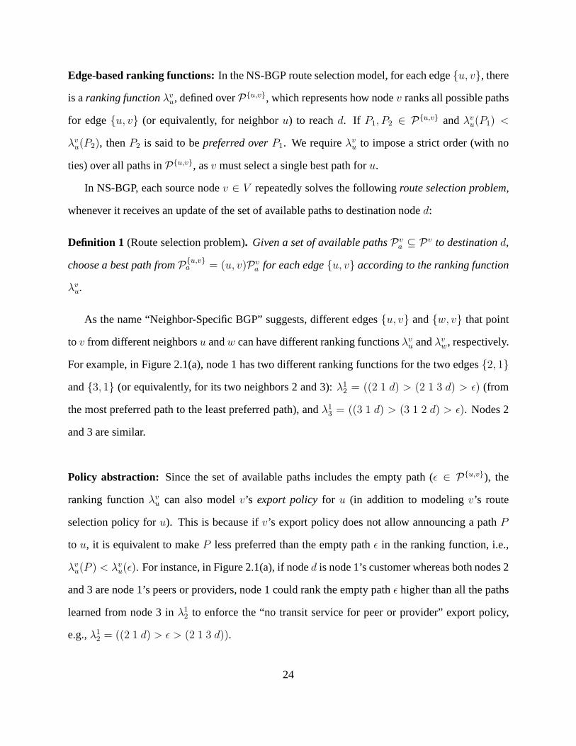
Edge-based ranking functions:In the NS-BGP route selection model, for each edge{u, v}, there
is aranking functionλvu, defined overP{u,v}, which represents how nodev ranks all possible paths
for edge{u, v} (or equivalently, for neighboru) to reachd. If P1, P2 ∈ P{u,v} andλvu(P1) <
λvu(P2), thenP2 is said to bepreferred overP1. We requireλv
u to impose a strict order (with no
ties) over all paths inP{u,v}, asv must select a single best path foru.
In NS-BGP, each source nodev ∈ V repeatedly solves the followingroute selection problem,
whenever it receives an update of the set of available paths to destination noded:
Definition 1 (Route selection problem). Given a set of available pathsPva ⊆ Pv to destinationd,
choose a best path fromP{u,v}a = (u, v)Pv
a for each edge{u, v} according to the ranking function
λvu.
As the name “Neighbor-Specific BGP” suggests, different edges{u, v} and{w, v} that point
to v from different neighborsu andw can have different ranking functionsλvu andλv
w, respectively.
For example, in Figure 2.1(a), node 1 has two different ranking functions for the two edges{2, 1}
and{3, 1} (or equivalently, for its two neighbors 2 and 3):λ12 = ((2 1 d) > (2 1 3 d) > ǫ) (from
the most preferred path to the least preferred path), andλ13 = ((3 1 d) > (3 1 2 d) > ǫ). Nodes 2
and 3 are similar.
Policy abstraction: Since the set of available paths includes the empty path (ǫ ∈ P{u,v}), the
ranking functionλvu can also modelv’s export policyfor u (in addition to modelingv’s route
selection policy foru). This is because ifv’s export policy does not allow announcing a pathP
to u, it is equivalent to makeP less preferred than the empty pathǫ in the ranking function, i.e.,
λvu(P ) < λv
u(ǫ). For instance, in Figure 2.1(a), if noded is node 1’s customer whereas both nodes 2
and 3 are node 1’s peers or providers, node 1 could rank the empty pathǫ higher than all the paths
learned from node 3 inλ12 to enforce the “no transit service for peer or provider” export policy,
e.g.,λ12 = ((2 1 d) > ǫ > (2 1 3 d)).
24

2.2.3 Stable Path Assignment
Section 2.2.2 defines the route selection model everyindividual node uses in NS-BGP. We now
define thecollectiveoutcome of the route selection processes run by the individual nodes — the
path assignment.
Definition 2 (Path assignment). An NS-BGPpath assignmentis a functionπ that maps each edge
{u, v} ∈ E to a pathπ({u, v}) ∈ P{u,v}. π({u, v}) = ǫ means that{u, v} is not assigned a path
to d.
Definition 3 (Consistent path assignment). A consistent path assignmentis a path assignment for
which the following statement is true: For each{u, v} ∈ E, if π({u, v}) has{v, w} as its second
edge (right after{u, v}), thenπ({u, v}) = (u, v)π({v, w}).
Definition 4 (Stable path assignment). A path assignmentπ is stable at edge{u, v} if the following
two statements are true: (1)π is a consistent path assignment, (2) For every edge{v, w} ∈ E, if
π({u, v}) 6= (u, v)π({v, w}), thenλvu((u, v)π({v, w})) < λv
u({u, v}).
This definition implies that, if a path assignment of edge{u, v} is stable, it will not change
given any possible available routes. For example, in Figure2.1(a), a stable path assignment for all
edges is shown in Table 2.1.
Table 2.1: An example of stable path assignment for the system shown in Figure 2.1(a)
Edge Stable path of the edge Edge Stable path of the edge{1, d} (1 d) {2, d} (2 d)
{3, d} (3 d) {1, 2} (1 2 d)
{1, 3} (1 3 d) {2, 1} (2 1 d)
{2, 3} (2 3 d) {3, 1} (3 1 d)
{3, 2} (3 2 d)
25
2.2.4 BGP vs. NS-BGP
Our model differs from the conventional BGP model [48] in thefollowing three respects.
Ranking function(s): node-basedvs. edge-based:The conventional BGP model requiresv to
use a single ranking functionλv for all neighbors, as shown in 2.1(b), offering little flexibility for
nodev to select the path that best meets an individual neighbor’s need. In contrast, the NS-BGP
model allows each edge{u, v} to have a separate ranking functionλvu, which allowsv to provide
customized route selection for individual neighbors, as shown in Figure 2.1(a).
Path assignment: node-basedvs. edge-based:In the conventional BGP model, everynodev gets
assigned one pathπ(u). As a result, all ofu’s neighbors learn the same path fromu 1. Whereas in
the NS-BGP model, everyedge{u, v} is assigned a pathπ({u, v}). This allows every nodeu to
simultaneouslyutilize up tok paths to forward traffic from its neighbors as well as its own traffic,
wherek is the number of nodesv ∈ V such that{u, v} ∈ E.
Export policy modeling: separate vs. integrated: Although conventional BGP supports per
neighbor export policies, it uses a single ranking functionλv to select routes for all neighbors.
As a result, export policies must be modeledseparatelyfrom the route selection process. Such
separation is no longer necessary in the NS-BGP model, as node v’s export policy for neighbor
u can be conveniently incorporated in the ranking functionλvu. For example, ifu is v’s peer or
provider, in the ranking functionλvu, v can simply rank the empty pathǫ higher than all peer- or
provider-learned paths to implement the “no transit service for peer or provider” export policy.
1In practice, an AS usually consists of multiple routers, each of which may learn different paths. Thus, neighborsconnect to the AS atdifferentedge routers might learn different paths, due to “hot potatorouting”. Nevertheless,NS-BGP provides a far more flexible and systematic way for ASes to provide customized route-selection service,independent of whether neighbors connect to the same edge router or not.
26

2.3 Sufficient Conditions for NS-BGP Stability
The “Gao-Rexford” conditions [43] state that, if all ASes follow the export, preference, and topol-
ogy conditions, BGP is guaranteed to converge to a stable state. Fortunately, we find that much
lessrestrictive conditions are sufficient to guarantee convergence under themore flexibleNS-BGP.
Specifically, the “prefer customer” condition is no longer needed in NS-BGP—individual ASes
can freely chooseany “exportable” routes without compromising global stability. In this section,
we first define the notion ofNS-BGP safety, which implies that an NS-BGP routing system always
converges to a stable path assignment. We then reviewIterated Dominance(presented in [86]),
the machinery we use in our proof. We next present simple examples that illustrate why NS-BGP
requires less restrictive conditions for safety than conventional BGP, before presenting the proof
of our safety result.
2.3.1 Formal Definition of NS-BGP Safety
For any policy-based (non-shortest-path) routing protocol (such as BGP or NS-BGP),safetyis a
top concern, as persistent route oscillations can significantly impact end-to-end performance, and
even threaten the reachability of network destinations. BGPsafetycan be loosely defined as a rout-
ing system that always converges to a “stable” state. Recallthat a stable state is a path assignment
that does not change given any possible route announcements. Thus, once a system is in a stable
state, it will never experience any further changes (provided the network topology and every node’s
routing policy remain the same). To formally define NS-BGP safety, we first need to introduce the
notion of “AS activation sequences”.
AS activation sequences:As in conventional BGP, the routing outcome of NS-BGP is built, hop-
by-hop, as knowledge about how to reach a destinationd propagates throughout the network. The
process begins whend announces itself to its neighbors by sending update messages. From this
27

moment forward, every nodev repeatedly picks a path for each edge{u, v} ∈ E, based on the most
recent updates of routes tod it received from its neighbors. As in [49, 48], the network isassumed
to beasynchronous. That is, edges can beactivated(i.e., get assigned new paths) at different times,
and update messages can be delayed or even lost (as long as they are retransmitted eventually). We
refer readers to [48] for a thorough explanation of this asynchronous environment.
Definition 5. An NS-BGP routing system is safe if it always converges to a stable path assignment
from any initial path assignment, and for any AS activation sequence.
2.3.2 Iterated Dominance
It was observed in [86] that all known conditions that guarantee the safety of conventional BGP
(e.g., “No Dispute Wheel” [48] and the “Gao-Rexford” conditions [43]) share a common struc-
ture [86], referred to as “Iterated Dominance”. This property is related to the notion of dominance-
solvability in game theory [76]. Iterated Dominance is an underlying structure of a routing in-
stance, which will enable us to show that, for any activationsequence, NS-BGP is bound to con-
verge to auniquestable state. Informally, Iterated Dominance means that, as time advances, nodes’
feasible choices of routes gradually become more and more limited, until eventually every node’s
route is fixed. Thus, Iterated Dominance provides us the means to present aconstructive, and
general, proof for NS-BGP safety.
We shall later show that the commercial setting considered in this chapter is simply a special
case of Iterated Dominance. To define Iterated Dominance, wefirst require the following defini-
tions:
Definition 6 (Consistent paths I). We say two pathsP1 and P2 are consistentif the following
statement holds: For every edge{i, j} that is on bothP1 andP2, the suffix ofP1 that leads fromj
to d is identical to the suffix ofP2 that leads fromj to d. In addition, two paths are also consistent
if they that do not share any common edge.
28

Definition 7 (Consistent paths II). Let P = {P1, . . . , Pk} be a set of paths inG. We say that a
pathQ in G is consistent withP if it is consistent with every path inP.
Definition 8 (Feasible paths). LetP = {P1, . . . , Pk} be a set of paths inG. We define the set of
feasiblepathsQ givenP to be the set of all paths inG that are consistent withP.
Definition 9 (Iterated Dominance). We say thatIterated Dominanceholds if there exists an order
over all edges inG: e1, . . . , e|E| (ei ∈ E, 1 ≤ i ≤ |E|), for which the following three statements
hold:
• There exists a set of pathsPe1, . . . , Pe|E|
such that for every1 ≤ i ≤ |E|, Peiis a path tod
that hasei as the first edge.
• For every1 ≤ i ≤ |E|, Pei= eiPek
for some0 ≤ k < i. (We definee0 to be the empty path
ǫ).
• For every1 ≤ i ≤ |E|, Peiis ei’s most preferred path in the set of feasible path given
{Pe1, . . . , Pe|E|
}.
Intuitively, this definition means that once the paths assigned to edges that come before a certain
edge are fixed, that edge’s path is its most preferred feasible path. Iterated Dominance has the nice
property that, if it exists in a routing system, it triviallyand intuitively induces convergence to a
stable path assignment.
Proposition 2.3.1. If Iterated Dominance holds for an interdomain routing instance, then NS-
BGP is safe for that routing instance. Moreover, NS-BGP always converges to a unique stable
path assignment.
Proof. The proof immediately follows from the Iterated Dominance property. If Iterated Domi-
nance holds then there must be an order over the edgese1, . . . , e|E| such that, for every1 ≤ k ≤ |E|
an edgeek can be assigned its most preferred feasible path (given thate1, . . . , ek−1 are assigned
29
Pe1, . . . , Pek
), regardless of what paths are assigned toek+1, . . . , e|E|. Thus, we can simulate the ex-
ecution of an activation sequence of NS-BGP, which shows that the routing system must converge
to a unique stable path assignment:
At some point in timee1 will learn of its most preferred pathPe1. From that moment forward,
e1 will stick to the pathPe1(which, by the definition of Iterated Dominance, is always available
to e1). Now, considere2. Oncee1’s path is fixed, by the definition of Iterated Dominance,e2 can
get its most preferred feasible pathPe2. Therefore, from some moment in time onwards (when an
update message containingPe2reachese2), e2’s path will be fixed and never change. By definition
of Iterated Dominance, we can continue iteratively fixing other edges’ paths until every edge has a
fixed path. Observe that the resulting path assignment is stable, because after each edgeei gets its
pathPei, it will never switch to other paths.
2.3.3 Examples of Safe NS-BGP Systems
Before presenting the formal proof of our main result, we first use an example to illustrate why
safety might be easier to achieve for NS-BGP than for conventional BGP. Figure 2.1(b) shows a
routing system in which BGP will always diverge, which is called BGPBAD GADGET [48]. In this
example,λ1, λ2 andλ3 are the ranking functions of nodes1, 2 and3, respectively. It is easy to con-
struct an activation sequence (presented as a sequence of path assignments) according to the rank-
ing functions, for example: ((1 d), (2 d), (3 d)) → ((1 2 d), (2 d), (3 d)) → ((1 2 d), (2 3 d), (3 d))
→ ((1 d), (2 3 d), (3 d)) → ((1 d), (2 3 d), (3 1 d)) → ((1 d), (2 d), (3 1 d)) → ((1 2 d), (2 d),
(3 1 d)) → ((1 2 d), (2 d), (3 d)) → ((1 2 d), (2 3 d), (3 d)) . (An underlined path indicates that it
has changed from the previous path assignment.) Notice thatthe third path assignment is the same
as the last path assignment. Therefore, the system will continue to oscillate and never terminate.
To see how NS-BGP can help in cases like this, we transformed the BGP routing system in
Figure 2.1(b) to an “equivalent” NS-BGP system in Figure 2.1(a). This is an “extreme” example in
that we assume every node is willing to select paths for each incoming edge (i.e., each neighbor)
30
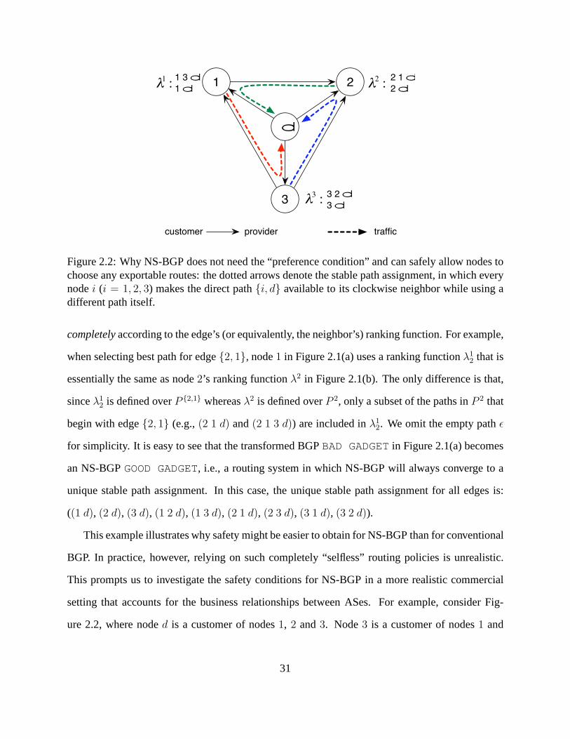
21
d
3
1 3 d
1 d
2 1 d
2 d
3 2 d
3 dλ3 :
λ1 : λ2 :
customer provider traffic
Figure 2.2: Why NS-BGP does not need the “preference condition” and can safely allow nodes tochoose any exportable routes: the dotted arrows denote the stable path assignment, in which everynodei (i = 1, 2, 3) makes the direct path{i, d} available to its clockwise neighbor while using adifferent path itself.
completelyaccording to the edge’s (or equivalently, the neighbor’s) ranking function. For example,
when selecting best path for edge{2, 1}, node1 in Figure 2.1(a) uses a ranking functionλ12 that is
essentially the same as node2’s ranking functionλ2 in Figure 2.1(b). The only difference is that,
sinceλ12 is defined overP {2,1} whereasλ2 is defined overP 2, only a subset of the paths inP 2 that
begin with edge{2, 1} (e.g.,(2 1 d) and(2 1 3 d)) are included inλ12. We omit the empty pathǫ
for simplicity. It is easy to see that the transformed BGPBAD GADGET in Figure 2.1(a) becomes
an NS-BGPGOOD GADGET, i.e., a routing system in which NS-BGP will always convergeto a
unique stable path assignment. In this case, the unique stable path assignment for all edges is:
((1 d), (2 d), (3 d), (1 2 d), (1 3 d), (2 1 d), (2 3 d), (3 1 d), (3 2 d)).
This example illustrates why safety might be easier to obtain for NS-BGP than for conventional
BGP. In practice, however, relying on such completely “selfless” routing policies is unrealistic.
This prompts us to investigate the safety conditions for NS-BGP in a more realistic commercial
setting that accounts for the business relationships between ASes. For example, consider Fig-
ure 2.2, where noded is a customer of nodes1, 2 and3. Node3 is a customer of nodes1 and
31

2, and node1 is a customer of node2. It is easy to see there is no “customer-provider” cycle
in the graph so the topology condition holds. We also requirenodes1, 2 and3 to adhere to the
export condition and export only customer routes to peers orproviders. Now we compare BGP
and NS-BGP and analyze why the “prefer customer” condition is necessary in conventional BGP
but redundant in NS-BGP. First, note that the ranking function λ3 prefers provider-learned route
(3 2 d) over customer-learned route(3 d), violating the preference condition for the regular BGP.
As a result, (not surprisingly) the routing system is a BGPBAD GADGET.
A key observation about the instability of the BGP system in Figure 2.2 is that theavailability
of route(1 3 d) to node1 is dependent upon theunavailabilityof route(3 2 d) to node3—if route
(3 2 d) is available to3, it will choose route(3 2 d) over(3 d), and announce no route to node1;
whereas if route(3 2 d) is not available to3, it will choose route(3 d) and announce it to node1
(since(3 d) is a customer-learned route). Things work differently in NS-BGP. NS-BGP ensures
that a route announced to a peer or provider does not change based on the presence or absence
of any non-exportable(e.g., peer- or provider-learned) routes. That is, in this example, node3
learning(3 2 d) (a provider-learned route) should not affect whether node3 exports(3 d) to node
1 (which is also a provider). Fundamentally, this is because,in NS-BGP, node3 can announce a
different route(3 d) to node1 than the route it selects for its own traffic, namely(3 2 d).
2.3.4 Safety Conditions for NS-BGP
To prepare for our analysis, we first define some terminology:We say that an edgee = {u, v} ∈ E
is acustomer edgeif v is u’s customer. Similarly, we say that an edgee = {u, v} is apeer edgeor
a provider edgeif v is u’s peer or provider, respectively. Observe that the “No customer-provider
cycle” topology condition in the “Gao-Rexford” guidelinescan now be interpreted as stating that
there must be no cycles in the graph containing only customeredges or only provider edges. Also
observe that the “Export only customer routes to peer or providers” condition means that if a path
32

P contains a customer edge or a peer edge, then all edges that come after that edge (towards the
destination) must also be customer edges, allowing us to simply disregard all other types of paths
in our analysis.
Lemma 2.3.2. If the Topology and Export conditions hold for an NS-BGP routing instance, then
Iterated Dominance holds for that routing instance.
Proof. We shall show that an order over edgese1, ..., e|E|, as in the definition of Iterated Domi-
nance, exists. Obviously, we can sete1 to be any edge of the form{u, d} ({u, d} ∈ E) as(u d)
is the only path that edge has tod. So by settingPe1= (u d), we have found an edgee1 that fits
the definition of Iterated Dominance. The rest of the proof shows how to prove the existence of an
edgee2, as required by the definition of Iterated Dominance. The same method can then be applied
recursively to finde3, . . . , e|E| (thus concluding the proof).
If there is another edge of the form{u, d}, we can now sete2 to be that edge for the same
reason as before. We shall now show how to finde2 as in the definition of Iterated Dominance, if
this is not the case. Informally, the proof shall now proceedby iteratively applying the following
procedure: Fix an edgee. Go over its most preferred feasible route (givenPe1) until reaching the
edge before last,l1. If edgel1 fits the description ofe2 then we are done. Otherwise, we apply the
same procedure tol1, moving to the edge before last onl1’s most preferred feasible path, calledl2
(which we regard as a new candidate to bee2). Thus, we create a sequence of edgesl1, l2, . . .. We
show that this procedure eventually reaches an edge that fitsthe description ofe2 (thus concluding
the proof), because otherwise the “No customer-provider cycle” will be violated (a contradiction).
Formally: Let e 6= e1 be some arbitrarily chosen edge. LetPe be e’s most preferred path
among all feasible paths givenPe1. For ease of exposition, we first consider the case in whiche is
a customer edge.
Now, to finde2, we shall construct a series of edgesl1, . . . , lk, . . . in the following manner: Let
(i j d) be the two-edge suffix ofPe (i.e., the last two edges onPe are{i, j} followed by{j, d}).
We setl1 to be{i, j}. If l1 prefers(i j d) over all other feasible paths, then we can sete2 to bel1
33

andPe2to be(i j d) (and are done). If, however,l1’s most preferred feasible pathPl1 is not(i j d),
we then consider the two-edge suffix ofPl1 and setl2 to be the first of these two edges. Forl2, we
repeat the same process we went through forl1. That is, eitherl2 prefers the two-edge suffix ofl1
over any other feasible path (in which case we sete2 to bel1, and are done), or we move on tol3
(which is the first edge ofl2’s most preferred path’s two-edge suffix). We continue this process,
constructing a series of edgesl1, . . . , lk, . . .. If this process terminates then we must have reached
an edge that fits the description ofe2.
We prove that this process must terminate by showing that if it does not terminate, we will
reach a contradiction to the topology condition (“No customer-provider cycles”).
First, observe that for any edgelj in the series of edgesl1, . . . , lk, . . ., there exists a path between
lj andlj+1 that consists only of customer edges. To see why this is true,considerl1. We assumed
thate was a customer edge. Therefore, by the export condition, anypath assigned toe must only
consist of customer edges. Sincel1 is on such a path, it must be a customer edge. Using the same
argument, we know thatl1 can only be assigned paths consisting of only customer edges. Since
l2 is, by definition, on such a path (l1’s most preferred feasible path), we have shown that the path
betweenl1 andl2 consists of customer edges only, so the claim holds forl1. We can now repeat the
same argument forl2, l3, etc.
Now, if the process does not terminate, then, since the number of edges is finite, some edgeli
will eventually appear twice in the sequencel1, . . . , lk, . . .. Consider the subsequence ofli, . . . , li
(betweenli’s first and second appearance). Because any two consecutiveedges in this cyclic se-
quence have a path between them that consists of only customer-edges, there must exist a customer-
provider cycle (i.e., a cycle of only customer edges).
The cases in whiche is a peer edge or a provider edge are handled similarly: Ife is a peer edge
then the edge that comes after it must be a customer edge, so the same arguments as before apply.
If e is a provider edge then the process described before will either go through a customer edge or
a peer edge (in which case, once again, the arguments above apply) or lead to a cycle of provider
34
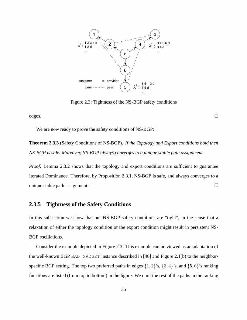
2 � 4
5
customer
31
1 2 3 4 d
1 2 d
...
5 6 1 2 d
5 6 d
...
λ1 :
provider
3 4 5 6 d
3 4 d
...
λ3 :
6
λ5 :peer peer
Figure 2.3: Tightness of the NS-BGP safety conditions
edges.
We are now ready to prove the safety conditions of NS-BGP:
Theorem 2.3.3(Safety Conditions of NS-BGP). If the Topology and Export conditions hold then
NS-BGP is safe. Moreover, NS-BGP always converges to a unique stable path assignment.
Proof. Lemma 2.3.2 shows that the topology and export conditions are sufficient to guarantee
Iterated Dominance. Therefore, by Proposition 2.3.1, NS-BGP is safe, and always converges to a
unique stable path assignment.
2.3.5 Tightness of the Safety Conditions
In this subsection we show that our NS-BGP safety conditionsare “tight”, in the sense that a
relaxation of either the topology condition or the export condition might result in persistent NS-
BGP oscillations.
Consider the example depicted in Figure 2.3. This example can be viewed as an adaptation of
the well-known BGPBAD GADGET instance described in [48] and Figure 2.1(b) to the neighbor-
specific BGP setting. The top two preferred paths in edges{1, 2}’s, {3, 4}’s, and{5, 6}’s ranking
functions are listed (from top to bottom) in the figure. We omit the rest of the paths in the ranking
35

functions for simplicity, as they play no roles in this example. The business relationships between
the ASes are described in the figure (where the arrows point from customers to their providers).
Observe that the topology condition holds as there are no customer-provider cycles. If we as-
sume that the export constraint also holds then, by Theorem 2.3.3, this NS-BGP routing system is
guaranteed to converge to a unique stable path assignment.
What happens if the export condition is removed (i.e., not followed)? We claim that the system
will then have no stable path assignment and so will oscillate indefinitely. Observe that if node2
follows the export condition, it cannot export path(2 3 4 d) to node1, making path(1 2 3 4 d)
unavailable to node1. Similarly, paths(3 4 5 6 d) and(5 6 1 2 d) are not available to nodes3
and5, respectively. But if the export condition is not followed,these paths will become available.
Assume, to lead to a contradiction, that a stable path assignment exists when the export condition
is removed. Observe that edge{1, 2} must either get the path(1 2 d) or (1 2 3 4 d) in this path
assignment (as it will not settle for a less preferred path than its second preferred path(1 2 d) that
is always available). Let us first consider the possibility that{1, 2}’s path in this stable assignment
is (1 2 d). If that is the case, then{5, 6} must be getting the path(5 6 1 2 d). This means that
node5 will not announce(5 6 d) to node4 (because node6 announces(6 1 2 d), rather than(6 d),
to node5). Therefore, edge{3, 4} is assigned the path(3 4 d), which, in turn, means that edge
{1, 2} can get its most preferred path(1 2 3 4 d). Now we have a contradiction—edge{1, 2}
has an available path(1 2 3 4 d) which it prefers over the path it is assigned in the stable path
assignment(1 2 d). Observe that if, instead, we assume that edge{1, 2} gets path(1 2 3 4 d) in the
stable path assignment, then edge{3, 4} must get path(3 4 d) in the stable path assignment. We
can continue this inference process like above and eventually reach a similar contradiction to edge
{1, 2}’s assigned path.
We have shown that without the export condition, not only is NS-BGP safety not guaranteed but
there might not even be a stable path assignment to which it can converge. We make the observation
that this is also the case if we remove the topology condition(while leaving the export condition
36

alone). Consider the same example, only with the following business relationship changes: make
nodes3, 5, and1 customers of nodes2, 4, and6, respectively. Observe that the topology condition
no longer holds as we now have a customer-provider cycle (3 → 2 → 1 → 6 → 5 → 4 → 3).
Also observe that paths(1 2 3 4 d), (3 4 5 6 d), and(5 6 1 2 d) are nowallowedby the export
condition as a result of the changes in the business relationships we made. Therefore, we can use
the same analysis as above to show that no stable path assignment exists if the topology condition
is removed.
2.4 Practical Implications
In this section we discuss three practical implications of the NS-BGP safety conditions presented
in Section 2.3. Specifically, we show that:
1. Our NS-BGP safety conditions are robust, in the sense thatthey hold even in the presence of
topology changes (e.g., the addition and removal of nodes and/or links due to new business
contracts, creation, merger, or disappearance of ASes, network failures, etc.).
2. It is safeto deploy NS-BGP incrementally. Global routing stability is guaranteed even if
only some of the ASes run NS-BGP, while others continue to runBGP. Moreover, the global
routing system is still guaranteed to converge to auniquestable path assignment.
3. By allowing arbitrary ranking of exportable paths, NS-BGP naturally supports the important
class of “backup” business relationships (i.e., an AS having a backup provider) and is less
prone to “Wedgies” [45] than conventional BGP.
Our NS-BGP safety conditions also provide useful guidance for solving the stability prob-
lems of internal BGP (iBGP) within an AS.
37

2.4.1 Safe Under Topology Changes
We have shown is Section 2.3.4 (Theorem 2.3.3) that if the topology and export conditions hold for
a routing instance, then NS-BGP is guaranteed to converge toa stable path assignment. However,
does this result still hold in the presence of topology changes? We make the observation that our
NS-BGP safety conditionsare robust in the presence of topology changes.
We first consider topology changes that result in theremovalsof edges and/or vertices from
the graphG in our model. Such changes can happen due to network failures(e.g., equipment
failures, fiber cuts) or business relationship changes (e.g., termination of a existing BGP peering
relationship). We observe that, if the topology condition and the export condition hold for a routing
instance, they cannot be violated by removing edges and/or vertices from the network. Hence, after
the removal of certain edges and/or vertices, we will end up with a new routing instance for which
these two conditions still hold. By Theorem 2.3.3, NS-BGP safety of the new routing instance is
guaranteed.
Similarly, when there are topology changes that result in theadditionsof edges and/or vertices
from the graphG in our model (e.g., due to the establishment of a new AS or a newBGP peering
relationship), we note that our proof of Theorem 2.3.3 stillholds for the new routing instance after
the topology changes, as long as they do not violate the topology and export conditions. That is,
the new vertices and/or edges do not create “customer-provider” cycles and they follow the “export
only customer routes to peer or provider” export policy. Since ASes have economic incentive to
follow the two conditions, the new routing instance is guaranteed to remain safe.
2.4.2 Safe in Partial Deployment
The proof of the NS-BGP safety conditions in Section 2.3 assumes all ASes in the network run
NS-BGP, i.e., afull deploymentof NS-BGP. However, the actual deployment of NS-BGP will cer-
tainly startincrementally, as any AS that has deployed NS-BGP individually can immediately start
38
offering customized route-selection services without collaboration. Therefore, a natural question
is whether the NS-BGP safety conditions still hold in apartial deploymentscenario (with some
“early adopter” ASes running NS-BGP, while other ASes stillrunning conventional BGP)?
As we shall now show, the answer to this question isYES. That is, NS-BGP can be (under
reasonable and realistic assumptions)incrementally- and partially-deployedwithout causing per-
sistent protocol oscillations. We observe that, using the exact same techniques we have used to
prove Theorem 2.3.3, we can actually prove a much more general result2:
Theorem 2.4.1. If topology and export conditions hold for a routing system,then, even if some
ASes are running NS-BGP while other ASes are still running BGP, as long as the preference con-
dition applies tothe ASes running conventional BGP(it is not needed for ASes running NS-BGP),
the routing system will always converge to a unique stable path assignment.
That is, as long as the ASesnot running NS-BGPprefer customer routes to other routes in their
route selection, the system will remain safe. We note that this result holds trueregardlessof the
number of ASes that are not running NS-BGP, andregardlessof the locations of these ASes in the
network. This result therefore generalizes both Theorem 2.3.3 (which considers cases in whichall
ASes are running NS-BGP) and the “Gao-Rexford” conditions [43] (which apply to cases in which
all ASes are executing BGP).
We also observe that, by the same arguments as in Section 2.4.1 and 2.4.3, the above safety
conditions of a partial NS-BGP deployment still hold in the presence of network topology changes,
and a routing system with even partially deployed NS-BGP mayexperience fewer BGP Wedgies.
2.4.3 Safer With Backup Relationship
As we know, if all ASes follow the “Gao-Rexford” conditions,a BGP routing system is guar-
anteed to be stable. However, the “Gao-Rexford” conditionsonly apply to routing systems with
2We omit the details of the proof as it follows similar lines ofthe proof in Section 2.3.4.
39
the two most common business relationships (“customer-provider” and “peer-peer”). Yet, it has
been increasingly common for ASes to establish a third classof business relationships—“backup”
relationships—to prevent the loss of network connectivityafter a failure. The introduction of
backup relationships can cause a routing system to have two stable states (i.e., two stable path
assignments), and result in a type of routing anomaly known as aBGP Wedgie[45]. We first recall
the notion of BGP Wedgies, and then explain why backup relationships in an NS-BGP routing
system are less likely to result in BGP Wedgies.
BGP Wedgies: The term “BGP Wedgies”, coined in [45], refers to the following problem with
BGP: It is common for an AS to have two (or more) upstream providers to avoid a single point
of failure in network connectivity. In such cases, the AS usually places a relative preference on
the two links its providers use to reach it: one link is definedas the “primary” (preferred), while
the other one is defined as the “backup” link. A backup link is intended to be used only when the
primary link is temporarily unavailable, therefore is typically much less well-provisioned in terms
of bandwidth. It is expected that once the primary link is restored, all traffic should switch back
from the backup link to the primary link. BGP Wedgies are anomalous situations in which, even
after a failed primary link is restored, the BGP state of the routing system does not “flip back” to
the intended state that existed before the link failure.
Consider the example of a Wedgie in conventional BGP, as shown in Figure 2.4. ASd is a
customer of ASes1 and3, AS 1 is a customer of AS2, and ASes2 and3 are peers. ASd chooses
to use the link{d, 3} as the primary link and the link{d, 1} as the backup link. ASd instructs
AS 1 to use path(1 d) only when there is no other path available (e.g., using the BGP community
attribute to mark the path(1 d) as “backup only” in its route updates). Assume that the original
BGP state is such that all ASes are forwarding their traffic toAS d along the path(1 2 3 d). Ob-
serve that this state is stable (as AS1 does not announce path(1 d) to AS 2 when path(1 2 3 d)
is available). Now, assume that link{3, d} goes down for some reason. Since the path(1 2 3 d) is
40

1
d
32
customer provider peer peer
primary linkbackup link
Figure 2.4: A BGP Wedgie: AS2 will not switch back to path(2 3 d) after the primary link{3, d}is restored from a failure.
no longer available, AS1 will announce path(1 d) to AS 2, which will in turn announce it to AS
3. In the end, traffic to ASd is forwarded along the path(3 2 1 d). Once link{d, 3} is restored,
a BGP Wedgie occurs: although AS3 will announce path(3 d) is available again, AS2 will not
switch back from its current customer-learned path(2 1 d) to a less preferred peer-learned path
(2 3 d), and will not announce the path(2 3 d) to AS 1. As a result, AS1 (and2) will keep using
the backup link even though the primary link has become available again.
NS-BGP helps prevent Wedgies:Let us revisit the example described above. Notice that the
Wedgie example in Figure 2.4 willnot occur if the routing system runs NS-BGP, because AS2
will have AS1’s ranking function (in this case,λ21 = ((1 2 3 d) > ǫ), and selects a path for AS
1 on its behalf. So when link{d, 3} is restored, AS2 will learn the path(3 d) from AS 3 again
and announce the path(2 3 d) to AS 1 because(1 2 3 d) is 1’s most preferred path. Once AS1
learns this path, it will withdraw the backup path(1 d) from AS 2 and AS2 will switch back to
use(2 3 d). Therefore, the system will be restored to the original state that existed before the link
failure.
As we have seen, NS-BGP prevents Wedgies in certain cases that would have been a problem
under conventional BGP. However, NS-BGP is not totally immune to Wedgies. To see this, con-
41

1
d
54
customer provider peer peer
primary linkbackup link
2 3
2 4 3 1 d
2 4 5 d
...
3 4 2 1 d
3 4 5 d
...
λ3
4:λ
2
4:
Figure 2.5: An NS-BGP Wedgie: ASes 2 and 3 will not switch backto the path through the primarylink {5, d} after it is restored from a failure.
sider the example in Figure 2.5. Assume that ASes2 and3 make their preferences known to their
provider AS4. In the normal case, all the ASes send their traffic through link {5, d}. If {5, d} fails,
then all ASes send traffic through{1, d}. After {5, d} is restored, AS4 will learn path(4 5 d) from
AS 5. But it will not announce the this path to neither2 or 3, because it has previously announced
more preferred paths to AS2 (path(4 3 1 d)) and AS3 (path(4 2 1 d)). Hence, AS1 will never
learn of the restoration of{5, d} and therefore will never withdraw the path(1 d). This results in a
Wedgie.
2.4.4 Preventing Instability in Internal BGP
We note that our NS-BGP safety results, while primarily addressing economic- and engineering-
related issues ininterdomainrouting, also have implications for routingwithin an AS. In practice,
an AS is itself a complex network consisting of multiple routers in different geographic locations.
In backbone networks, these routers exchange routing information using a variant of BGP known
asinternal BGP(iBGP). Since having an iBGP session between each pair of routers does not scale,
most large backbones useroute reflectorsor confederationsto impose a hierarchy for distributing
42

BGP routing information. A router configured as a route reflector selects a best route on behalf of
its client routers, obviating the need for the clients to maintain so many iBGP sessions or learn so
many BGP routes. However, previous work has shown that persistent route oscillation can easily
occur inside an AS [10, 51, 50], due to the complex interaction of iBGP and Interior Gateway
Protocols (IGPs) like OSPF and IS-IS.
The dissemination of routes between route reflectors, and between route reflectors and their
clients, parallels the business relationships between ASes in interdomain routing [51]. In partic-
ular, the relationship between a route reflector and its clients in iBGP is much the same as the
relationship between a provider AS and its customer ASes; similarly, the relationship between two
route reflectors is much the same as the relationship betweenpeer ASes in interdomain routing.
Depending on how the routers in the AS “rank” the routes they’ve learned, oscillations can re-
sult. In fact, a solution to this problem is to impose a “prefer route-reflector client” condition [51],
analogous to the “prefer customer” Gao-Rexford condition.(In practice, this imposes strict re-
strictions on the IGP configuration, to ensure that route reflectors are topologically “close” to their
clients.) Our results for NS-BGP suggest another, more flexible, solution—allow route reflectors
to announce different routes to different iBGP neighbors. In particular, a route reflector could dis-
seminate any client-learned route (such as the client-learned route with the closest egress point)
to its route-reflector peers, and any route (such as the routewith the closest egress point) to its
route-reflector clients. This small modification to iBGP would provably ensure iBGP convergence
without imposing any restrictions on the IGP configuration.
2.5 Deployment Issues
In this section, we discuss the implementation issues in deploying NS-BGP in practice. First, we
describe how an AS can correctly forward traffic from different neighbors (and from within its
own network) along different paths. We then discuss how to disseminate multiple routes to the
43

edge routers of an AS to enable flexible route selection. Finally, we present three models an NS-
BGP-enabled AS can use to provide different levels of customized route-selection services. When
deploying NS-BGP, an AS can handle all these issues by itselfwithout requiring any changes from
neighboring ASes, as no BGP message format or external BGP (eBGP) configuration are needed.
2.5.1 Neighbor-Specific Forwarding
NS-BGP requires routers to be able to forward traffic from different neighbors along different
paths. Fortunately, today’s routers already provide such capabilities. For example, the “virtual
routing and forwarding (VRF)” feature commonly used for Multi-protocol Label Switching Virtual
Private Networks (MPLS-VPNs) supports the installation ofdifferent forwarding-table entries for
different neighbors [77].
Since an AS typically consists of many routers, traffic entering from variousingressrouters of
the AS must be forwarded to the correctegressrouters. In conventional BGP, this is achieved in a
hop-by-hop fashion to ensure that all routers in the AS agreeto forward traffic to the closest egress
point that has one of potentially multiple “equally good” best paths to the destination. For example,
in Figure 2.6, ifR5 learns one path fromR3 and another path fromR4 to D, and the two routes
are considered “equally good” in BGP’s route-selection process, it will choose to use the closest
egress point (according to the IGP distances). However, this approach no longer works in NS-
BGP, as traffic entering the AS at the same ingress point may befrom different neighbors (ingress
links), and thus may need to be forwarded to different egresspoints, or different egress links of
the same egress point. Fortunately, ASes have an efficient solution available—encapsulation (or
tunneling). Many commercial routers deployed in today’s networks can perform MPLS or IP-
in-IP encapsulation/decapsulation at line rate. To provide customized forwarding for neighbors
connected at the same edge router, the tunnels need to be configured from ingresslinks (rather
than ingress routers) to egresslinks (rather than egress routers). For example, in Figure 2.6,C1’s
andC2’s traffic can be tunneled fromR1 to R6 andR7 (that connect to the same egress point
44

ISP Z
R1 R3
C1 A
R7
R4
R5
R2
R6
R8
R9
B
C
D
C2
C3
AS Z
Figure 2.6: AS Z has multiple interdomain routes for destination D
R3) independently. To avoid routers in neighboring domains having to decapsulate packets, egress
routers need to remove the encapsulation header before sending the packets to the next-hop router,
using technique similar to the penultimate hop popping [26]. Similar to transit traffic originated
from other ASes, traffic originated within the AS itself can also be forwarded to the correct egress
links using tunneling.
2.5.2 Route Dissemination Within an AS
A prerequisite for an edge router to provide meaningful “customized” route-selection services is
that it needs to have multiple available routes to choose from (otherwise, all its neighbors would
inevitably receive the same route). Unfortunately, the wayBGP routes are disseminated within
today’s ASes makes such “route visibility” often impossible. For example, in Figure 2.6, the AS
Z as a whole learns four routes to D from four different neighboring edge routers (R6, R7, R8,
R9). However, as BGP only allows a router to select and announcea single route for a destination,
routerR5 will only learn two of the available routes, one fromR3 andR4. Even worse,R1 and
R2 will only learn the one route selected byR5. For similar reasons, in large ASes where route
reflectors are commonly used for better scalability, most edge routers have significantly reduced
visibility of BGP routes [94].
Two different approaches can be used to provide better routevisibility to the edge routers of
45
an AS—a distributed approach and a (logically) centralizedone. In the distributed approach, a
router in the AS needs to be able todisseminatemultiple routes (per destination) to each neighbor.
For backwards compatibility, this can be achieved by using multiple internal BGP (iBGP) sessions
between routers. The BGP ADD-PATH extension, which supports the dissemination of multiple
routes (per destination) through one BGP session [56], makes the dissemination process much
more efficient. It is worth noting that, depending on how muchflexibility an AS plans to provide,
not all available routes need to be disseminated. For example, if an AS decides to have a couple of
notions of “best routes” (e.g., best of all routes, and best of customer-learned routes), it only needs
to disseminate at most two routes per destination (one of which must be a customer-learned route).
Different ASes can make different trade-offs between the overhead of disseminating more routes
within their own networks and the benefit of providing more routes to their neighbors to choose
from.
Alternatively, an AS can also improve its route visibility by using a logically-centralized Rout-
ing Control Platform (RCP) [15, 97, 103]. In this case, an AS can deploy a set of servers in its
network, each of which has a complete view of all available BGP routes. These servers then select
routes on behalf of all the edge routers and install the selected routes to the respective routers. This
logically-centralized approach can provide complete route visibility to the route-selection process
with good scalability and performance [15, 97, 103]. As the desire for more flexible route selec-
tion grows, an RCP-like approach starts to make more sense, as it imposes less burden on route
dissemination within an AS than the distributed approach.
2.5.3 Control Over Customized Selection
A big motivation of NS-BGP is to enable individual ASes to provide customized route-selection
services to their neighbors. Therefore, an NS-BGP-enabledAS needs to take its neighbors’ pref-
erences of routes into account when selecting routes. Here we describe how an AS can control
the amount of customer influence over its route-selection process, and how the customized route
46

selection can be realized.
An AS i can use different models to grant its neighborj different levels of control over the
ranking functionλij. For example, ASi could adopt a“subscription” model, in which it offers
several different services (ranking functions) for its neighbors to choose from, such as “shortest
path”, “most secure”, and “least expensive”. A neighborj has the flexibility to decide which one
to “subscribe” to, but does not have direct influence on how the ranking functions are specified.
Although more flexible than conventional BGP, this model is astill fairly restrictive. For neighbors
that require maximum flexibility in choosing their routes, an AS could offer a“total-control”
model. In this model, ASi gives neighborj direct and complete control over the ranking function
λij. Therefore,j is guaranteed to receive its most preferred routes among allof i’s available routes.
For neighbors that require a level of flexibility that is in between what the previous two models
offer, an AS could adopt a third,“hybrid” model. In this model, neighborj is allowed to specify
certain preference to ASi directly (e.g., avoid paths containing an untrusted AS if possible). When
determining the ranking functionλij for j, i takes bothj’s preference and its own preference into
account (as the “best route” according toj’s preference may not be the best fori’s economic
interest). Nevertheless,i still controls how much influence (“weight”)j’s preference has on the
ranking functionλij .
In Chapter 3, we describe in detail how these different models can be implemented by using
a new, weighted-sum-based route-selection process with anintuitive configuration interface [103].
When deciding which model(s) to offer, an AS needs to consider the flexibility required by its
neighbors as well as thescalability of its network, as the three service models impose different
resource requirements on the provider’s network. For example, the “subscription” model intro-
duces the least overhead in terms of forwarding table size, route dissemination and customized
route selection (e.g., each edge router or RCP server only needs to run a small number of route
selection processes). On the other hand, the “total-control” model, while providing the finest grain
of customization, imposes the most demanding requirementson system resources and results in the
47

highest cost for the provider. Therefore, we expect an AS to only provide such service to a small
number of neighbors for a relatively high price. Since the costs of offering the three types of service
models are in line with the degrees of flexibility they offer,we believe that an AS can economically
benefit from offering any one or more of these models with appropriate pricing strategy.
It is worth mentioning that the “hybrid” and “total-control” models can be realized in two
different ways. The simpler way is that the neighborj tells the ASi whatλij to use, soi only needs
to select and export one route toj. The other way is thati announces all exportable routes toj, and
j selects amongst them itself. The latter approach allows thej to hide its policy (ranking function)
but requiresi’s ability to export multiple routes toj, andj’s ability to directly tunnel its traffic to
i’s egress links. Finally, the NS-BGP safety conditions (Theorem 2.3.3) hold regardless of which
one(s) of these three models are used.
2.6 NS-BGP and Incentives
Most studies of BGP make the implicit assumption that ASes will obediently adhere to the protocol.
Recently, there has been a surge of interest in BGP’sincentive-compatibilityproperties [36, 37, 67,
86, 44], motivated by the fact that ASes are independent entities with different, sometimes com-
peting, economic interests. Given that NS-BGP provides a new interdomain route selection model,
we are curious about its incentive-compatibility properties, and how these properties compare to
BGP’s. In this section, we examine NS-BGP from a game-theoretic perspective, and explore the
possibility of making it incentive compatible. Unfortunately, we find that, as in conventional BGP,
rational ASes have an incentive to lie about the paths they are using in NS-BGP. Therefore, unlike
the positive routing stability results presented earlier in this chapter, the transition from BGP to
NS-BGP doesnot improve the incentive-compatibility properties of a routing system. However,
we argue that NS-BGP (and BGP) will remain stable even in the presence of protocol manipulation.
48

2
4
51
1 2 3 4 d
1 2 3 5 d
1 3 4 d
1 3 5 d
1 2 d
2 3 4 d
2 d
2 3 5 d
λ1 :
λ2 :
provider
3 4 d
3 5 dλ3 :
customer
Figure 2.7: A system that is not incentive compatible in bothBGP and NS-BGP
2.6.1 Background: BGP is Not Incentive-Compatible
Informally, saying that “BGP is incentive compatible” means that if all other ASes are following
the rules of BGP, then the best course of action for an AS is to do the same (i.e., it has no incentive
not to do so). We refer readers to [67] for an explanation of this framework.
Unfortunately, as observed in [67], conventional BGP is notnecessarily incentive compatible
even in small networks. This problem is further aggravated in realistic commercial settings in
which ASes might be interested in attracting traffic from customers [44] to make more profit. Here
we first illustrate the incentive-related problems with BGPusing a simple example. This example
also helps us in our later analysis of the incentive-compatibility properties of NS-BGP.
Consider the simple example illustrated in Figure 2.7, in which all three “Gao-Rexford” safety
conditions hold. Assume that for AS3, its main interest is attracting AS1’s traffic (i.e., making
AS 1 forward trafficdirectly to AS3), which is more important than attracting2’s traffic, which, in
turn, is more important than the path it uses to send its outgoing traffic tod. Further, assume that
3 is bound by business contracts to provide connectivity to its customers, and thus must always
announcesomepath to ASes1 and2. Observe that if AS3 announces the path(3 4 d) (its most
preferred route for outgoing traffic) to AS2, AS 2 will choose path(2 3 4 d) and let AS1 get its
most preferred path(1 2 3 4 d). However, if AS3, even though still only using path(3 4 d) to
49

forward all the traffic tod, announces the path(3 5 d) to AS 2 (but still announces path(3 4 d)
to AS 1), AS 2 will choose the path(2 d) and announce it to AS1. This way, AS1 will choose
path(1 3 4 d) and forward its traffic directly through AS3. This example shows that AS3 can
improve its gain by announcing a path that it isnot actually using to one of its customers. This
inconsistency between the path AS3 announces AS2 and actual path it uses to forward2’s traffic
is clearly an anomaly that should not happen (and is not expected by AS2).
2.6.2 NS-BGP is Not Incentive-Compatible
We observe that the above counter-example for the incentive-compatibility of BGP can be easily
extended to the NS-BGP setting. Now, assume that ASes1 and2 made their ranking functions
known to their provider AS3. If AS 3 honestly follows NS-BGP, it should announce path(3 4 d)
to AS 2 (as it knows path(2 3 4 d) is AS 2’s most preferred path). However, as in the BGP
case, doing that will cause AS3 to lose AS1’s (direct) traffic. If AS3 ignores AS2’s ranking
function, and announces path(3 5 d) to AS2 instead, it will be able to attract AS1’s (direct) traffic
and improve its gain. This simple example shows that ASes mayhave incentive to deviate from
NS-BGP even in routing systems where the NS-BGP safety conditions hold.
2.6.3 Not Being Incentive-Compatible Does Not Affect Stability
We argue that BGP and NS-BGP not being incentive compatible in general doesnot necessar-
ily mean that the respective routing systems will become unstable in the presence of unorthodox
protocol manipulations. That is, while ASes might improve certain kinds of individual gains by
manipulating these protocols, such actions are unlikely toaffect the global routing stability.
This is because both the BGP safety conditions (the “Gao-Rexford” conditions) and the NS-
BGP safety conditions (Theorem 2.3.3) aremotivated byanddescriptive ofthe actual economic
interests of ASes, and thereforereflectASes’ behaviors in reality. Hence, an AS does not have an
50
economic incentive to violate theexport condition(and carry transit traffic from peers or providers
for free), or thetopology condition(and serve as its own direct or indirect “provider”). Given
these observations, we argue that, while ASes can manipulate NS-BGP in various ways, they
have no incentive (and are unlikely) to break the NS-BGP safety conditions that guarantee global
routing stability. Nevertheless, the lack of incentive compatibility of BGP and NS-BGP can cause
problems like inconsistencies between the path announced by an AS and the actual path it uses
to forward traffic. Hence, identifying sufficient conditions for incentive compatibility remains an
important research problem.
2.7 Related Work
This chapter has two main areas of related work: more flexibleinterdomain route selection and
interdomain routing stability. Recently, there has been anincrease in the interest of providing more
flexibility in interdomain route selection, from theoretical formalism and modeling of policy-based
routing with non-strict preferences [20], to stability conditions of interdomain route selection for
traffic engineering [111], to Routing Control Platform (RCP)-type systems that provide various
degrees of customization support in BGP route selection [96, 97, 103].
A huge amount of effort has been put into understanding BGP’sstability properties. Griffinet
al.’s seminal work modeled BGP as a distributed algorithm for solving theStable Paths Problem,
and derived a theoretic sufficient condition (i.e., “No Dispute Wheel”) for BGP stability [48]. Gao
et al. proved a set of three practical conditions (i.e., the “Gao-Rexford” conditions) that guarantees
BGP stability and also reflects the common business practices in today’s Internet [43]. Gaoet al.
later extended their results to cover backup routing with BGP protocol extension and preference
guidelines [42]. Feamsteret al. explored the trade-off between the expressiveness of rankings and
interdomain routing safety, and found if ASes are granted with complete flexibility with export
(filtering) policies (i.e., can violate the export condition of the “Gao-Rexford” conditions), only
51

shortest-paths based ranking can guarantee stability [35].
2.8 Summary
This chapter presents Neighbor-Specific BGP (NS-BGP), an extension to BGP that provides both
greatpracticalbenefits to ASes that deploy it and newtheoreticalcontributions to the understand-
ing of the fundamental trade-off between local policy flexibility and global routing stability. The
NS-BGP model we propose enables individual ASes to offer customized route-selection services
to neighbors. We prove that, comparing to conventional BGP,a less restrictive sufficient condition
can guarantee the stability of the more flexible NS-BGP. Our stability conditions allow an AS to
selectanyexportable routes for its neighbors without compromising global stability. We also show
that NS-BGP remains stable even in partial deployment and inthe presence of network failures,
as long as the stability conditions are followed. We discussthe practical issues associated with
deploying NS-BGP and show it can be readily deployed by individual ASes independently.
52
Chapter 3
Morpheus: Making Flexible Policies Easier
to Configure
3.1 Introduction
In Chapter 2, we made the case that large ISPs have the incentive and the path diversity to meet
the diverse requirements of its customers. We also proved that Neighbor-Specific BGP is a safe
model that an ISP could use to realize routing policies that make flexibletrade-offsamongst many
different objectives, such as implementing business relationships with neighboring domains, pro-
viding good end-to-end performance to customers, improving the scalability of routing protocols,
and protecting the network from attacks [16].
However, theconfigurabilityof ISP networks, i.e., the degree to which networks can becus-
tomizedto implement flexible routing policies, is limited because of the unnatural restrictions that
BGP imposes on the way ISPs select routes. BGP was designed when the Internet consisted of
a small number of autonomous systems (ASes). Given the very limited path diversity within the
small set of ASes, there was little need for a route selectionprocess that supports configuration
of flexible routing policies. However, as the Internet started to grow and path diversity increased,
53

network operators started to demand more flexibility to configure more complex policies. The re-
sponse from the vendors and standards communities was an incremental “patchwork” of backward
compatible features to add attributes and steps to the BGP decision process [1]. (For example,
AS PATH was introduced in BGP-2, NEXTHOP was introduced in BGP-3, and LOCALPREF
was introduced in BGP-4.) The outcome was a decision processthat is counter-intuitive and noto-
riously hard to configure. Today, despite the rich path diversity available to large ISPs, configura-
bility is limited by restrictions imposed by virtually every aspect of policy configuration such as
the routing architecture, the BGP software implementation, and its configuration interface.
For instance, each BGP router selects a single “best” route for each prefix, forcing all neighbor-
ing ASes connected to the same edge router to learn the same route, even if some customers would
be willing to pay a higher price to use other routes. Within each router, the standard BGP imple-
mentation selects routes only based on the attributes of theBGP updates, falling short of realizing
routing policies that, for example, require using outside measurement data. Finally, current BGP
decision process imposes inherent restrictions on the policies an ISP can realize [80]. Consisting
of a series of tie-breaking steps, the BGP decision process compares one attribute at a time until
only one best route remains. The ordering of steps imposes a strict rankingon the route attributes,
making it impossible to realize flexible policies that maketrade-offsbetween policy objectives.
For example, a useful policy that strikes a balance between revenue and route stability could be:
“If all routes are unstable, pick the most stable path (of anylength through any kind of neighbor),
otherwise pick the shortest stable path through a customer (then peer, and finally provider).”How-
ever, this seemingly simple policy cannot be realized today. In addition, policy objectives that are
not part of the original BGP protocol, such as security and performance, are hard to add into its
decision process, even if the importance of these objectives becomes obvious over time.
Stepping back, we ask the question: “Starting from a clean slate, how can wedesign for con-
figurability?” That is, instead of seeking the best way to configure the existing system, we design
a new system with configurability as a first-order goal. To make the new system practically adopt-
54

able, we focus on solutions that do not require cooperation between domains. Since ISPs are
often business competitors, cooperation among them has proved notoriously difficult in practice.
This constraint essentially prevents changes to theinterdomainrouting protocol that require col-
laboration of multiple domains. Fortunately, such changesare not necessary—as mentioned in
Section 2.1, large ISPs have a lot of path diversity, and can safely and effectively “act alone” in
applying many flexible routing policies.
To design for configurability, we consider the followingroute selection probleman ISP faces:
Given a set of available routesR = {r1, r2, ..., rn} for a prefixp, choose a best router∗ for each
router according to a set of criteriaC = {c1, c2, ..., ck}. The set of criteria (i.e., policy objectives)
includes route characteristics such as stability, security, and performance. These criteria may be
conflicting in the sense that no route is the best with respectto all criteria simultaneously. There-
fore, to design for configurability, the routing system mustensure that the network administrator
has the flexibility to make arbitrary trade-offs among the criteria. Our solution to the route selec-
tion problem is a system that we callMorpheusas it gives ISPs the power to “shape” their routing
policies. Morpheus relies on the following system components:
• A routing architecture that is responsible for (1) learning the “inputs” and (2) disseminating
the “outputs” of the route selection problem. The routing architecture allows a set ofMorpheus
serversto choose the best routes from the setR = {r1, r2, ..., rn} of all routes available to the
AS, and ensures that the servers can assign any route inR independentlyto each neighbor without
restrictions.
• A server software architecture giving the network operators the ability to make trade-offs
among the criteria{c1, c2, ..., ck}. It includes a set ofpolicy classifiersand one or moredecision
processes. Each classifier tags routes with criteria-specific labels.The decision process computes
a cumulative score as a weighted sum of the labels for each route and picks the route with the
highest score. To pick potentially different routes for different neighbor networks (as supported
55
by the routing architecture), multiple decision processes(possibly one per neighbor) can run in
parallel.
• A configuration interface through which network operators can configure the decision pro-
cesses. The straightforward method for a network operator to configure a decision process is to
directly specify a weight for each criterion. However, without a systematic procedure for deter-
mining what the weights should be, this method would be errorprone. Morpheus provides such
a systematic procedure based on the Analytic Hierarchy Process (AHP) [85], which derives the
appropriate weights based on operator’s preferences on thepolicy objectives.
We have implemented Morpheus as a routing control platform consisting of a small number
of servers that select BGP routes in a logically centralizedway. Previous work on centralized
routing platforms [15, 97, 96] has demonstrated that they can be made scalable and reliable enough
for deployment in large ISP networks without sacrificing backwards compatibility. However, the
previous work mainly focused on thefeasibility of such logically centralized system, stopping
short of addressing the poor configurability of BGP policies. In particular, the previous work did
not identify the necessary supports for configurability from the routing architecture and proposed
only limited improvements in the BGP decision process and its configuration interface.
The rest of the chapter is organized as follows. In Section 3.2, we identify the necessary
changes to the current routing architecture in order to support flexible policies. We present the
software architecture of the Morpheus server in Section 3.3, and give examples on how to config-
ure routing policies through its AHP-based configuration interface in Section 3.4. Section 3.5 de-
scribes the prototype implementation of Morpheus as extension to the XORP software router [53].
Section 3.6 presents the evaluation of the prototype Morpheus server and demonstrates that the
gain in flexible policies does not come at the expense of scalability and efficiency. Finally, we
present related work in Section 3.7 and summarize the chapter in Section 3.8.
56
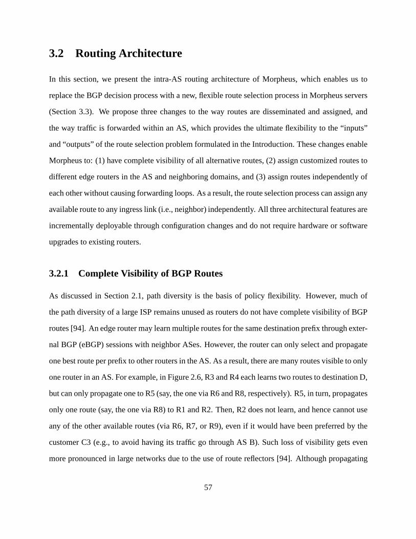
3.2 Routing Architecture
In this section, we present the intra-AS routing architecture of Morpheus, which enables us to
replace the BGP decision process with a new, flexible route selection process in Morpheus servers
(Section 3.3). We propose three changes to the way routes aredisseminated and assigned, and
the way traffic is forwarded within an AS, which provides the ultimate flexibility to the “inputs”
and “outputs” of the route selection problem formulated in the Introduction. These changes enable
Morpheus to: (1) have complete visibility of all alternative routes, (2) assign customized routes to
different edge routers in the AS and neighboring domains, and (3) assign routes independently of
each other without causing forwarding loops. As a result, the route selection process can assign any
available route to any ingress link (i.e., neighbor) independently. All three architectural features are
incrementally deployable through configuration changes and do not require hardware or software
upgrades to existing routers.
3.2.1 Complete Visibility of BGP Routes
As discussed in Section 2.1, path diversity is the basis of policy flexibility. However, much of
the path diversity of a large ISP remains unused as routers donot have complete visibility of BGP
routes [94]. An edge router may learn multiple routes for thesame destination prefix through exter-
nal BGP (eBGP) sessions with neighbor ASes. However, the router can only select and propagate
one best route per prefix to other routers in the AS. As a result, there are many routes visible to only
one router in an AS. For example, in Figure 2.6, R3 and R4 each learns two routes to destination D,
but can only propagate one to R5 (say, the one via R6 and R8, respectively). R5, in turn, propagates
only one route (say, the one via R8) to R1 and R2. Then, R2 does not learn, and hence cannot use
any of the other available routes (via R6, R7, or R9), even if it would have been preferred by the
customer C3 (e.g., to avoid having its traffic go through AS B). Such loss of visibility gets even
more pronounced in large networks due to the use of route reflectors [94]. Although propagating
57
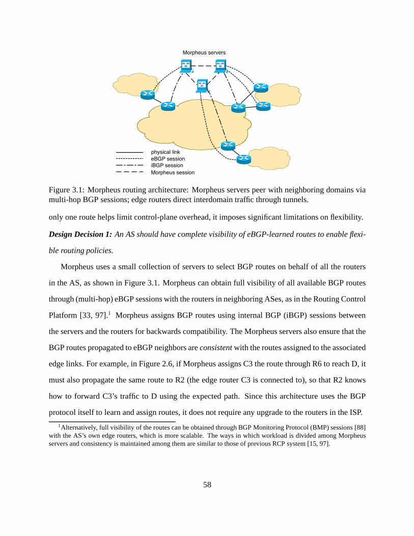
Morpheus servers
iBGP session
eBGP session
physical link
Morpheus session
Figure 3.1: Morpheus routing architecture: Morpheus servers peer with neighboring domains viamulti-hop BGP sessions; edge routers direct interdomain traffic through tunnels.
only one route helps limit control-plane overhead, it imposes significant limitations on flexibility.
Design Decision 1: An AS should have complete visibility of eBGP-learned routes to enable flexi-
ble routing policies.
Morpheus uses a small collection of servers to select BGP routes on behalf of all the routers
in the AS, as shown in Figure 3.1. Morpheus can obtain full visibility of all available BGP routes
through (multi-hop) eBGP sessions with the routers in neighboring ASes, as in the Routing Control
Platform [33, 97].1 Morpheus assigns BGP routes using internal BGP (iBGP) sessions between
the servers and the routers for backwards compatibility. The Morpheus servers also ensure that the
BGP routes propagated to eBGP neighbors areconsistentwith the routes assigned to the associated
edge links. For example, in Figure 2.6, if Morpheus assigns C3 the route through R6 to reach D, it
must also propagate the same route to R2 (the edge router C3 isconnected to), so that R2 knows
how to forward C3’s traffic to D using the expected path. Sincethis architecture uses the BGP
protocol itself to learn and assign routes, it does not require any upgrade to the routers in the ISP.
1Alternatively, full visibility of the routes can be obtained through BGP Monitoring Protocol (BMP) sessions [88]with the AS’s own edge routers, which is more scalable. The ways in which workload is divided among Morpheusservers and consistency is maintained among them are similar to those of previous RCP system [15, 97].
58

3.2.2 Flexible Route Assignment
Evenwith complete visibility of alternative routes, today’s BGP-speaking routers cannot assign
different paths to different customers. In Figure 2.6, the two customers C1 and C2 connected to
the same edge router R1 may want to use the two different pathsthrough the same egress point
R3 to reach D, respectively. To make such policy possible, the AS must have the ability to (1)
use available paths through anyegress link(rather thanegress router) flexibly, and (2) assign those
routes to the ingress linksindependently(whether or not they connect to the same edge router).
Design Decision 2: An AS should be able to assign any route through any egress link to any ingress
link independently.
With full visibility of all eBGP-learned routes, Morpheus can easily pick the best routes through
any egress link for its customers and edge routers individually. Morpheus can disseminate multiple
routes per prefix to edge routers in several ways.2 Since the edge routers are no longer responsible
for propagating BGP routing information to neighbor ASes, Morpheus does not need to send all of
the route attributes—only the destination prefix and next-hop address are strictly necessary. This
enables a significant memory reduction on edge routers. Uponreceiving these routes, edge routers
can use the “virtual routing and forwarding (VRF)” feature commonly used for MPLS-VPNs to
install different forwarding-table entries for differentcustomers [77].
3.2.3 Consistent Packet Forwarding
With the flexibility of assigning any route through any egress link to any neighbor independently,
extra care needs be taken in the data plane to avoid introducing forwarding loops. When a router
has multiple “equally good” routes, it is common practice topick the route through the “closest”
egress point, based on the Interior Gateway Protocol (IGP) weights, a.k.a. hot-potato routing. For
2This can be achieved by using the “route target” attributes commonly used with VRF in MPLS-VPN [77], orhaving multiple iBGP sessions between a Morpheus server andan edge router. Other options include using the BGP“add-paths” capability [100].
59

example, in Figure 2.6, if the routes to D through link R3-R6 and link R4-R9 have the same local
preference and AS-path length, and if R1 is closer to R3 than to R4 (in terms of IGP weights),
R1 will pick the route through R3-R6. Hot-potato routing ensures consistent forwarding decisions
among the routers in the network. For example, if R1 picks theroute through R3-R6 to reach D,
other routers on the forwarding path (i.e., R5 and R3) are guaranteed to make the same decision.
However, hot-potato routing introduces problems of its own. First, it significantly restricts
the policies an AS can realize. For example, in Figure 2.6, R1and R2 connect to a common
intermediate router R5. Hot-potato routing forces them to use the same egress point, rather than
allowing (say) R1 to use R3 and R2 to use R4. In addition, a small IGP change can trigger routers to
change egress points for many prefixes at once, leading to large traffic shifts and heavy processing
demands on the routers [93].
Design Decision 3: The routers in an AS should forward packets from the ingress link to its as-
signed egress link.
To achieve this goal, Morpheus relies on IP-in-IP or MPLS tunnels to direct traffic between
edge links. This design choice offers several important advantages, beyond allowing flexible route
assignment without the risk of forwarding anomalies. First, Morpheus can rely on the IGP to
determine how traffic flows between ingress and egress routers, reducing the complexity of the
Morpheus server and ensuring fast reaction to internal topology changes. Second, Morpheus does
not need to select BGP routes for the internal routers, reducing the total number of routers it has to
manage. MPLS or IP-in-IP tunneling is readily available at line rate in many commercial routers,
and a “BGP-free core” is increasingly common in large ISPs. In Morpheus, packets are tunneled
between edgelinks (rather than between edge routers as is common today). To avoid routers in
neighboring domains (e.g., R6 in Figure 2.6) having to decapsulate packets, edge routers (e.g., R3)
need to remove the encapsulation header as part of forwarding the packets, using technique similar
to penultimate hop popping [26].
60
BGP
Updates
Best
route
Route
classification
Best route selection
(decision process)
The route selection process
Weights of
policy criteria
R
Classifier 1
Classifier 2
Classifier k
FC
r*
a1
a2
wi
ak
External
information
Figure 3.2: Morpheus’ BGP route selection process, which includes route classification and bestroute selection.
3.3 Server Software Architecture
The Morpheus server needs to solve theroute selection problemintroduced in Section 3.1:Given
a set of available routesR = {r1, r2, ..., rn} for a prefixp, choose a best router∗ according to a set
of criteria C = {c1, c2, ..., ck} for each neighboring router.This problem naturally devolves into
two main steps: (i)classifyingthe routes based on each criterion and (ii)selectingthe best route
based on the set of criteria, as shown in Figure 3.2. Eachpolicy classifiertags every received route
based on a single policy objective. Eachdecision processpicks a best route according to the tags
using a “decision function”FC that is configured to realize a particular routing policy. A Morpheus
server can run multiple decision processes in parallel, each with a different routing policy, to pick
customized routes for different neighbors.
3.3.1 Multiple Independent Policy Classifiers
The introduction of policy classifiers provides flexibilityby providing a separate attribute for each
policy objective, and incorporating “side information” into route selection.
61

Separate Attribute for Each Policy Objective
The BGP decision process selects best routes by examining one BGP attribute at a time, e.g., first
“local-preference”, followed by “AS-path length” and so on. As BGP policies involve more and
more policy objectives, many of them are forced to be realized by using the same BGP attribute.
For example, to realize the common business relationship policy of “prefer customer routes over
peer routes, and prefer peer routes over provider routes”, customer / peer / provider routes could
be assigned with local-preference value of 100 / 90 / 80, respectively. At the same time, operators
often increase or decrease the local-preference of a route to make it more or less favorable in
the decision process to control the traffic load of certain links. In fact, many other complicated
rules are also overloaded to “local preference” via mechanisms such as “route-maps” toindirectly
influence BGP’s multi-stage decision process. The lack of separate attributes for individual policy
objectives causes policy configuration to become immenselyconvoluted, as the attribute overload
becomes more severe.
Design Decision 4: A Morpheus server should use a separate attribute for each policy objective.
Morpheus’ policy classifiers realize this design decision by tagging the routes. Each classifier
takes a route as input, examines the route according to a specific policy criterion, and generates
a tag that is affixed to the route as metadata. For example, a business-relationship classifier may
tag a route as “customer”, “peer”, or “provider”; a latency classifier may tag a route with the mea-
sured latency of its forwarding path; a loss classifier may tag a route with the measured loss rate
of the path; a stability classifier may tag a route with a penalty score that denotes the instability
of the route (using, for example, a route-flap damping algorithm [98]); a security classifier that
detects suspicious routes (e.g., those being hijacked) maytag a route as “suspicious” or “unsuspi-
cious” [59].
Each policy classifier works independently and has its own tag space, obviating the need to
overload the same attribute. It also makes it easy to extend the system with a new policy objective
62

by adding a new classifier, without changing or affecting anyexisting ones. Furthermore, when
a new module needs to be incorporated into the system, upgrades need only be applied to the
Morpheus servers instead of all routers in the AS. These classifier-generated tags are purely local
to Morpheus, and are never exported with BGP update messages; as such, using these tags does
not require any changes to any routers.
By tagging the routes, rather than filtering or suppressing them, the decision process is guaran-
teed to have full visibility of all valid candidate routes (except those that are ill-formed or cannot
be used under any circumstances, e.g., those with loops in their AS paths). This is in sharp contrast
to the current BGP implementation in which all the routes forthe same prefix may be filtered or
suppressed (e.g., in the case of route-flap damping), sometimes leaving the decision process with
no route to choose from.
Incorporate Side Information
Another issue that limits the flexibility of routing policies is the lack ofside information. Many
useful routing policies require additional information that is not part of the BGP updates. For
example, to select the route with the shortest latency to a destination, we need performance mea-
surement data. (As mentioned in Section 2.1.1, the AS-path length is a poor indicator of path
latency.) In general, side information about route properties includesexternal informationsuch
the business relationships with the neighbors, measurement data, or a registry of prefix ownership,
andinternal statessuch as a history of ASes that originated a prefix (which can beused to detect
prefix hijacking [59]), or statistics of route instability.However, there was no systematic mecha-
nism to incorporate side information in routers. Network operators had to either “hack” their BGP
configurations in an indirect and clumsy way (e.g., tweaking“route-maps”), or wait for software
upgrades from router vendors (if the need for certain side information becomes compelling) and
then upgrade a large number of routers3.
3Recently, several RCP-type systems started to offer the similar ability to incorporate side information [96, 97].
63

Design Decision 5: A Morpheus server should be able to use external informationand / or keep
internal state when determining the properties of routes.
The introduction of policy classifiers makes it easy to incorporate side information as each pol-
icy classifier can have access to different external data sources containing the information needed to
classify the routes. For example, the business-relationships classifier can have access to up-to-date
information about the ISP’s business relationships with neighboring ASes through a corresponding
configuration file. A latency classifier and a loss classifier can get measurement information about
path quality from a separate performance monitoring system, or a reputation system (e.g., ASX
is well known to have long latency or a high loss rate). A security classifier can have access to a
registry of prefixes and their corresponding owners.
Different classifiers can also maintain separate internal states. For instance, a stability classi-
fier can maintain statistics about route announcement and withdrawal frequencies. A route security
module that implements Pretty Good BGP (PGBGP)—a simple algorithm that can effectively de-
tect BGP prefix and subprefix hijacks—can keep past history ofBGP updates in the pasth days
(whereh is a configurable parameter) [59].
Care needs to be taken when taking performance metrics (e.g., latency and loss) into the de-
cision process, as these properties of a path could potentially change quickly with time. Recent
studies suggest that it is possible to factor performance into route selection in a stable way [58, 54].
We plan to further investigate the trade-off between route stability and the responsiveness of route
selection to performance changes in the context of Morpheus(e.g., use a timer in the classifiers to
control how often the performance properties of routes change in the decision process).
3.3.2 Multiple Weighted-Sum Decision Processes
The Morpheus server uses a weighted-sum decision process torealize trade-offs amongst different
objectives. It also supports running multiple decision processes in parallel to realize different
customized policies simultaneously.
64

Weighted-sum for Flexible Trade-offs
The conventional step-by-step BGP decision process imposes a strict ranking of route attributes,
starting with local preference and followed by AS-path length and so on. As a result, policies that
strike a trade-off among policy objectives are hard to realize, such as the example mentioned in
Section 3.1 that balances stability and business relationships.
Design Decision 6: The Morpheus decision process should support trade-offs among policy ob-
jectives.
To achieve this goal, the decision functionFC in the route selection problem formulation (as
mentioned in Section 3.1) must allow trade-offs among policy objectives. A simple, yet powerful
method is theweighted-sum. For example, for a router ∈ R (whereR is the set of alternative
routes), its weighted-sumscoreis:
S(r) =∑
ci∈C
wi · ai(r) (3.1)
wherewi is theweightfor criterionci in C, andai(r) is router’s rating of criterioni. For a prefix
p, the decision functionFC selects the route with the highest score as the best choice:
r∗ = FC(r) = arg maxr∈R(p)
S(r) (3.2)
We choose the weighted sum as the basis of Morpheus’ decisionprocess for three reasons. First,
the weighted sum provides an expressive way to make trade-offs between the criteria through the
configuration of their weights, and it can also be used to express a sequential process like the
standard BGP decision process. Second, weighted sums are simple to compute and thus well-
suited to making routing decisions in real time. Third, it allows us to leverage Analytic Hierarchy
Process (AHP), a technique in decision theory, to design a simple and intuitive configuration in-
terface, which can automatically derive the weights according to operator’s preferences on policy
65

Classifier 1
Export
PolicyClassifier 2
Classifier 3
Score
Function A
Mapping
Function
Mapping
Function
Mapping
Function
Mapping
Function
Mapping
Function
Mapping
Function
tag1
tag2
tag3
Score
Function B
Decision Process A
Decision Process B
Score
comparison &
tie-breaking
Score
comparison &
tie-breaking
�1
A
M2
A
M3
A
M1
B
M2
B
M3
B
a1
A
a2
A
a3
A
a1
B
a2
B
a3
B
�A = ��A ⋅ ��A∑
�B = ��B ⋅ �B∑
Figure 3.3: Each decision process consists of a set of mapping functions of the policy objectivesand a score function. Different decision processes are configured with different mapping functionsand/or score functions to realize different policies.
objectives (as discussed in Section 3.4).
Morpheus instantiates one decision process for each routing policy and supports running mul-
tiple decision processes in parallel. To allow different decision processes tointerpreta policy tag
differently, each decision process has a set of “mapping functions” before the “score function”, as
shown in Figure 3.3. The introduction of the mapping functions offers two major benefits.
First, the introduction of the mapping functions decouplesthegenerationof tags (the job of the
classifiers), and theinterpretationof tags (the job of the mapping functions). This way, each policy
classifier can tag routes in its own tag space without worrying about the consistency with other
classifiers. This facilitates the implementation of classifiers by third parties. With the mapping
functions, network operators can simply “plug and play” different classifier modules. The mapping
functions can ensure that all tags are converted to the same uniform numerical space to make the
comparison between different policy criteria meaningful.We believe this open platform will foster
the sharing of classifier modules in the operations community and may also lead in the long run to
the emergence of a market centered around these modules.
Second, the mapping functions enables different policies to interpret the same policy tagdif-
66
ferently. For example, one policy may want to set a threshold for routestability and treat all
routes with penalty values below the threshold as “equally stable”, while another policy may want
to always select the most stable route available. As shown inFigure 3.3, the same tagtag1 can
be mapped to different ratingsaA1 and aB
1 by two different mapping functionsMA1 andMB
1 .
Therefore, network operators can realize different policies through different configurations of the
mapping functions (as well as weights of the policy objectives), as illustrated by the examples in
Section 3.4.
After passing the mapping functions, the route is sent to thescore function which computes its
score, as shown in Figure 3.3. Then the scores of all the routes for the same destination prefix are
compared, and the route with the highest score is picked as the best route. If there are multiple
routes with the same highest score, the operators have the choice to break the tie using different
mechanisms, such as configuring a (potentially different) ranking of egress links for each ingress
link, and pick the route with the highest egress link rankingas the best route [102]; or simply using
router ID. As in conventional BGP, the export policy module after the decision process makes the
final decision on whether to send the route out or filter it.
Parallel Decision Processes for Customized Policies
BGP allows an AS to influence how other ASes reach itself (e.g., through the use of BGP com-
munities). However, BGP provides no mechanism for an AS to influence how its provider picks
routes for it to reach the rest of the Internet. However, suchcoordination is increasingly impor-
tant as more customers want routes with particular properties (e.g., low latency, high bandwidth,
good security). For example, many content providers (e.g.,social network Web sites) rely on their
ISPs to reach their users (i.e., the “eyeballs”). To get closer to the “eyeballs”, content providers
commonly buy services from multiple transit providers and use only the routes that meet their per-
formance requirements. This is not economical for the content provider. A transit provider that
could flexibly assign the routes based on customers’ preferences would have an advantage over
67

other ISPs in attracting customers.
Design Decision 7: An AS should allow its neighbors (e.g., its customers) to influence its routing
policies by specifying their preferences.
To support different customer choices, Morpheus supports the realization of multiple indepen-
dent routing policies simultaneously, through the parallel execution of multiple decision processes,
each selecting its own best routes, as shown in Figure 3.3.
To avoid changing the BGP protocol, Morpheus uses an out-of-band communication channel
for customers to specify preferences through a simple configuration interface. For example, the
provider could allow a customer to independently and directly configure the weights in a decision
process. Alternatively, the provider could combine the customers’ preferences between certain
policy objectives, and combine them with its own preferences through an AHP-based configura-
tion interface (as discussed in Section 3.4). While providing a separate decision process for each
customer may introduce scalability challenges, we believein practice, the routes most customers
want can be reduced to a handful of types, such as low-latencyroutes, most secure routes, most sta-
ble routes, low-cost routes. The provider could simply provide these options to its customers, and
only provide customized decision processes to a very limited number of customers who demand
more control of their routes.
In any case, Morpheus provides an AS the ability to select routes based on a variety of fac-
tors. However, this extra flexibility should not come at the expense of global routing instability.
Fortunately, the NS-BGP stability conditions presented inSection 2.3 provide a useful guideline
for ISPs that want to offer flexible policies on a per neighbor(or per neighbor group) basis. In
addition, possible extensions of recent stable load-balancing techniques [31, 58, 39, 54, 7] can be
explored to prevent oscillations in interdomain load-sensitive routing. In both cases, considerable
flexibility in interdomain routing is possible without compromising global stability.
68
3.4 AHP-Based Policy Configurations
In this section, we present how to configure routing policiesin Morpheus. In theory, operators
could configure the mapping functions and the weights directly to realize policies. However,
humans are not good at setting a large number of weights directly to reflect their preferences.
Instead, studies show that humans do a much better job in expressing their preferences through
pairwise comparisons between alternatives, even though the results of these comparisons are often
inconsistent [85]. Based on this observation, Morpheus leverages the Analytic Hierarchy Process
(AHP) [85], a technique in decision theory, to provide a simple, intuitive configuration interface.
Network operators specify their policy preferences through pair-wise comparisons, and AHP au-
tomatically derives the weights of policy objectives and the appropriate ratings of the mapping
functions. After briefly explaining how AHP works in an “offline” fashion, we propose an “online”
version that is more appropriate for real-time route selection. We then show a policy configuration
example, in which the ISP allows its customer to configure part of the decision process. At the
same time, the ISP itself controls how much influence on the decision process the customer can
have.
3.4.1 The Offline AHP Configuration Process
AHP is a well-studied, widely-applied technique in Multi-Criteria Decision Analysis [11], a field
in decision theory. It provides a simple, yet systematic wayto find the overall best choice from
all alternatives, according to the decision maker’s preferences of the alternatives with regard to
individual criteria [85]. In interdomain routing policy, the alternatives are the available routes, the
decision maker is the network operator, and the criteria arethe policy objectives.
The first step in AHP is to model the decision problem as adecision hierarchy, as shown in
Figure 3.4. At the bottom of the hierarchy are thealternatives, i.e., the possible solutions of the
decision problem. One solution must be selected among the alternatives based on a set ofcriteria,
69

Goal
Criterion 1 Criterion 2 Criterion 3
Alternative 1 Alternative 2
Figure 3.4: The decision hierarchy of AHP.
as shown in the middle of the hierarchy. For each criterion, the decision maker then performs pair-
wise comparisons of all alternatives. For each comparison,the decision maker specifies his / her
preference of one alternative over the other using a number.The scale from 1 to 9 has proven to be
the most appropriate [85], in which, when comparing criteria p to q, 1 meansp andq are equally
preferred, 3 means weak preference forp overq, 5 means strong preference, 7 means demonstrated
(very strong) preference, 9 means extreme preference. The inverse values 1/3, 1/5, 1/7 and 1/9 are
used in the reverse order of the comparison (q vs. p). Intermediate values (2, 4, 6, 8) may be used
when compromise is in order.
Table 3.1: Comparison matrix
Loss Rate R1 (0.01) R2 (0.03) R3 (0.05) WeightR1 (0.01) 1 3 9 0.69R2 (0.03) 1/3 1 3 0.23R3 (0.05) 1/9 1/3 1 0.08
An example is shown in Table 3.1, where three alternative routesR1, R2, andR3 are com-
pared in pairs based on their loss rate. Note that although the table shows the entire matrix of 9
preferences, the operator only needs to specify 3 of them—“R1 vs. R2”, “ R1 vs. R3”, and “R2
vs. R3”. Here the operator weakly prefersR1 (with a loss rate of0.01) overR2 (with a loss rate of
0.03); strongly prefersR1 overR3 (with a loss rate of0.05); and weakly prefersR2 overR3. The
table also shows the weights of all alternatives, which are computed from the principal eigenvector
70

GOAL (1.00)
Latency
(0.14)
R1 (0.69)
R2 (0.23)
R3 (0.08)
R1 (0.62)
R2 (0.31)
R3 (0.07)
Loss rate
(0.14)
Business
Relationships
(0.72)
R1 (0.55)
R2 (0.36)
R3 (0.09)
Figure 3.5: Example of a decision hierarchy.
of the preference matrix [85]. In this case, the operator’s preferences are “consistent”, i.e., “R1 vs.
R3” (9) = “R1 vs. R2” (3) × “R2 vs. R3” (3), so the weights can be derived by normalizing the
values in any column of the preference matrix. However, humans are likely to giveinconsistent
answers in a series of pair-wise comparisons, and AHP provides a systematic way to deal with
inconsistency, as illustrated in the example in Section 3.4.3.
With operator’s preference of alternative routes on each criterion (e.g., business relationships,
latency and loss rate in Figure 3.5), AHP can derive the rating ai(r) of router for each criterioni,
as in Equation (3.1). To get the weightwi of each criterioni, the operator also needs to determine
the preference (relative importance) of different criteria through similar pair-wise comparisons of
criteria. With the preferences of all criteria pairs, AHP can derive the appropriate weight for every
criterion, and calculate the overall score of an alternative route using Equation (3.1). For example,
in the hierarchy shown in Figure 3.5,S(R1) = 0.72 × 0.55 + 0.14 × 0.69 + 0.14 × 0.62 = 0.58.
3.4.2 Adapting AHP to Work Online
Applying the conventional AHP technique to the route selection problem directly, as described in
Section 3.4.1, only works in anofflinefashion. This is because whenever a new route is received, a
human operator has to compare all alternatives routes in pairs with regard to every policy objective
(to get the ratingai(r)), which can not be done in real time.
71

To make the AHP-based decision process workonline, we replace the alternatives in the de-
cision hierarchy with a set ofsubcriteria. For example, in Figure 3.6, the business relationships
criterion can be divided into three subcriteria: customer,peer, and provider. This change allows
network operators to specify their preferences on each set of subcriteria offline, while enabling
the ratingsai(r) of received routes to be generated in real time. For example,for the business-
relationship criterion, an operator can specify his / her preference of customer / peer / provider
routes through pair-wise comparisons offline. The appropriate rating for each type of route will be
derived by AHP automatically and stored in the mapping function (as shown in Figure 3.3).
In summary, the online, AHP-based policy configuration process can be performed in three
steps: (1)Decompose:The network operator formulates the decision problem by identifying a
hierarchy of criteria (and subcriteria); (2)Specify preferences:For each pair of criteria at the
same level of the hierarchy and with the same “parent criterion”, the network operator specifies
his / her preference of one criterion over the other; (3)Derive weights: The preferences are orga-
nized in preference matrices and weights are derived by AHP using linear algebra operations [85].
Note that operators are only involved in the first two steps, and the third step is performed by the
configuration program automatically.
3.4.3 A Policy Configuration Example
As mentioned in Section 3.3, Morpheus enables an ISP to get input from its customers about
their preferences on routes. Here we give an example that shows how customer preference can be
incorporated into the decision process using the AHP-basedconfiguration interface.
Suppose the ISP has a customer C who is a content provider, andC has purchased the “premium
service” that allows it to specify its preference on the routes it learns from the ISP. As a content
provider, C is primarily interested in learning routes thathave low latency to the destinations
(i.e., to get the content closer to the “eyeballs”). The ISP,on the other hand, cares about the
“business relationships” property of the routes, as it would earn profit by forwarding traffic through
72

GOAL (1.00)
Business
Relationships
(1.00)
Latency
(0.714)
Security
(0.143)Stability
(0.143)
customer (0.692)
peer (0.231)
provider (0.077)
[0, 50ms) (0.672)
[50ms, 150ms) (0.265)
[150ms, infinity) (0.063)
suspicious (0.1)
unsuspicous (0.9)
[0, 70) (0.1)
[70,100] (0.9)
provider-specified
(0.125)customer-specified
(0.875)
Figure 3.6: The AHP hierarchy of an example routing policy.
a customer, and it would have to pay to forward traffic througha provider.
Figure 3.6 shows the AHP hierarchy of the routing policy, which takes four policy objectives
into account: business relationships, latency, stability, and security. As the first step of the config-
uration, the ISP needs to decide how much influence to the decision process it gives to customer
C. As a premium service, the ISP allows C to directly specify its preferences on all policy objec-
tives except business relationships. It also strongly prefers the customer-specified objectives over
the provider-specified objective, and enters “7” in the “customer-specified vs. provider-specified”
comparison. AHP then automatically derives the relative weights of the two types of objectives:
0.875 for the three customer-specified objectives (latency, stability, and security) and 0.125 for the
provider-specified objective (business relationships).
To determine the relative weights of latency, stability, and security, the customer C needs to
specify its preferences through pair-wise comparisons. Assuming that C enters “latency vs. stabil-
ity” = 5, “performance vs. security” = 5, and “stability vs. security” = 1, AHP can then derive the
weights of the three objectives: latency (0.714), stability (0.143), and security (0.143), as shown in
Figure 3.6.
Now that the weights of the four policy objectives are derived, the ISP and the customer C only
need to configure the corresponding mapping functions for the objectives. Assuming that the ISP
73
specifies its preferences on business relationships as: “customer vs. peer” = 3, “peer vs. provider”
= 3, and “customer vs. provider” = 9, then AHP automatically derives the ratings of the three
types of routes for the mapping function of business relationships. Upon receiving a route tagged
as “customer”, “peer”, or “provider” by the business relationship classifier, the mapping function
will assign it with a business relationship rating of 0.692,0.231, or 0.077, respectively.
For the latency mapping function, suppose the customer C is given three latency intervals:i1 =
[0, 50msec], i2 = [50msec, 150msec], andi3 = [150msec,∞], and it has the following preferences:
“ i1 vs. i2” = 5, “ i1 vs. i3” = 9, and “i2 vs. i3” = 3. AHP will then derive the ratings the mapping
function should use to map the routes that fall into the threeintervals: i1 = 0.672,i2 = 0.265,
and i3 = 0.063. While calculating the ratings, AHP also calculatesthe consistency ratioof the
preferences [85], where a consistency ratio of 0 means all preferences are consistent. In this case,
the three preferences are inconsistent (i.e., “i1 vs. i3” (9) 6= “ i1 vs. i2” (5) × “ i2 vs. i3” (3)), and
the consistency ratio is 0.028. AHP requires the consistency ratio to be no larger than 0.05 (n =
3), 0.08 (n = 4), or 0.1 (n ≥ 5) for a set of preferences to be acceptable, wheren is the number
of alternatives [85]. (As 0.028 is below the 0.05 threshold,this set of preferences is acceptable.)
When a set of preferences specified by an operator has a consistency ratio larger than the threshold,
Morpheus will request the operator to reset the preferences.
For stability, we assume the stability classifier runs an algorithm similar to the one used by
route-flap damping (RFD), and tags each route with a number between 0 and 100. The higher the
number is, the more stable the route is. The customer C treatsroutes with a stability tag below
70 as unstable, and it extremely prefers stable routes over unstable ones. For security, we assume
the security classifier runs the Pretty-Good BGP (PG-BGP) [59] algorithm, and tags every route as
either “suspicious” or “unsuspicious”. The customer C extremely prefers unsuspicious routes over
suspicious routes.
In a similar fashion, the provider can provide customized routing policies to different customers
using separate decision processes (as shown in Figure 3.3),and allow each customer to configure
74

Latency information
retrieved from PMS*
BGP
UpdatesExport
Policy
Business
Relationships
Decision
Processes
Import
PolicyStability Latency
Security
(PG-BGP)
Configuration
File
BGP
Updates
Configuration
File
*PMS: Performance Monitoring System
Figure 3.7: Morpheus prototype implemented as an extensionto XORP
certain policy objectives through the simple AHP-based interface.
3.5 Implementation
We have implemented a Morpheus prototype as an extension to the XORP software router plat-
form [53]. We first highlight the major changes we made to XORP, then describe the four policy
classifiers and the decision process we have implemented in greater detail.
3.5.1 Changes to XORP
We chose XORP as the base platform to implement our Morpheus prototype because its modular
structure closely parallels the Morpheus software architecture. However, since XORP is designed
to implement the standard BGP decision process operating ata single router, our prototype differs
from XORP’s BGP implementation in three key ways.
First, we implemented the weighted-sum-based decision process of Morpheus from scratch. It
has the ability to select different routes for different edge routers/peers, and can simultaneously
run multiple decision processes each having its own policy configuration.
Second, to demonstrate that a policy classifier is easy to implement and to evaluate the per-
formance of different such classifiers in action, we implemented four policy classifiers performing
classifications based on business relationships, latency,stability and security respectively. While
these classifiers could, in principle, work in parallel, in our prototype we implemented them as new
modules in the XORP message processing pipeline, as shown inFigure 3.7. Since the classifiers
75
work independently, the ordering amongst them is not critical.
Third, we modified XORP’s import and export-policy modules to bypass route-flap damping,
and ensure export consistency between edge routers and the neighboring domains connected to
them.
3.5.2 Policy Classifiers
In this section, we discuss in detail the four policy classifiers we have implemented thus far.
Business relationships:The business relationship classifier is linked to a configuration file that
contains a table of (next-hop AS, business relationship) pairs. When a Morpheus server is started,
it reads this file into memory. When a new route arrives, the classifier consults the table and assigns
the route with the appropriate tag (e.g., “customer”, “peer”, or “provider”).
Latency: Our latency classifier assumes there is a performance monitoring system (PMS) from
which it periodically pulls real-time latency informationabout paths between an ingress point to
an egress point, and from an egress link to a destination prefix. The retrieval of the performance
information is handled by a background process and the pulling interval can be adjusted to reach a
sweet spot between the freshness of the latency/loss information and the communication overhead
to the PMS.
The latency classifier generates two types of tags—the absolute latency and the relative latency,
to serve different policy needs—some policies only care about the relative latency amongst alter-
native paths (e.g., “always choose the path with the lowest latency”), while others may be specific
about absolute latency (e.g., “for all paths with latency less than 100 ms, choose the most stable
one through a customer”). To generate both types of tags, thelatency classifier internally keeps
records of the current path latencytnow and the minimum observed path latencytmin for each (pre-
fix, next-hop) pair. When a new route arrives, it is tagged with tnow in milliseconds as the absolute
latency, andtnow/tmin as the relative latency.
76

Stability: Our stability classifier implements the same penalty function as route flap damping
does [98]. However, instead of suppressing routes with a penalty exceeding a threshold, our sta-
bility module tags each route with a penalty score.
Security: Our security classifier implements Pretty Good BGP (PGBGP) [59], a simple yet effec-
tive heuristic algorithm that identifies bogus routes basedon a history of (prefix, origin AS) pairs.
A route is tagged as “suspicious” if a route’s AS path does notmatch the history of the lasth days
(whereh is a configurable parameter); or as “unsuspicious” otherwise. This classifier is ported
by the author of PGBGP from his original implementation, with a few interface changes. This
demonstrates that the design of Morpheus is friendly to third-party modules.
Amongst the four classifiers, three of them (except the business-relationships classifier) are
required to “re-tag” previously tagged routes when certainconditions are met. For example, the
latency classifier needs to re-tag a route if the change in path latency exceeds a certain threshold.
The stability classifier needs to re-tag a route when the decay of its penalty score exceeds certain
value. The PGBGP algorithm also requires to re-tag a “suspicious” route as “unsuspicious” if it is
not withdrawn after 24 hours. In all such cases, a configurable minimum re-tagging interval can
be set to prevent undesirable flapping effect. (The 24-hour interval in the PGBGP case is long
enough, so no additional constraint is needed.)
3.5.3 Decision Processes
We implemented the decision process with four mapping functions for the four classifiers, and
a weighted-sum score function, as described in Section 3.3.Our implementation assumes the
mapping functions and the score functions are specified in configuration files ahead of time. When
a new route arrives, a decision process only computes the score for this new route, without re-
calculating the scores for all previously received routes for the same prefix. In fact, the decision
process only compares the new route’s final score with the currenthighestscore of that prefix. On
77
the other hand, when the current best route is withdrawn, thedecision process compares the scores
of all remaining routes and picks the one with the highest score as the new best route.
It is possible that more than one route receives the same score. To select a single best route
for each peer/edge router in that case, Morpheus currently supports two types of tie-breaking
mechanisms—ranking of egress points, and router ID. In the rank-based tie-breaking scheme, each
edge router is assigned with a fixed (but configurable) ranking of all egress points. This ranking
may reflect geographic distance or the typical IGP distancesand link capacities between each pair
of ingress/egress points. By decoupling changes in the IGP distances from the decision processes,
the fixed-ranking scheme avoids the problems associated with hot-potato routing [93] and gives
the ISP additional control over the flow of traffic (e.g., decrease an ingress point’s ranking of a
particular egress point, if a link gets overloaded by the traffic from the ingress point to that egress
point). A closer coupling with the IGP distances, where needed, can be achieved on a longer time
scale by simply adjusting the configuration of the fixed ranking.
3.6 Implementation and Evaluation
In this section, we evaluate the performance and scalability of Morpheus using our XORP-based
prototype. Specifically, we answer three questions:
1. What is the performance of Morpheus’ policy classifiers and its score-based decision process?
We find that the Morpheus classifiers and decision process work efficiently. The average decision
time of Morpheus is only 20% of the average time the standard BGP decision process takes, when
there are 20 routes per prefix.
2. Can Morpheus keep up with the rate of BGP update messages in large ISPs?Our unoptimized
prototype is able to achieve a sustained throughput of 890 updates/s, while the aggregated update
arrival rate of a large tier-1 ISP is typically no larger than600 updates/s [97].
78

3. How many different policies (i.e., decision process instances) can Morpheus support effi-
ciently? Our experimental results show that our prototype can support 40 concurrent decision
processes while achieving a sustainable throughput of 740 updates/s.
3.6.1 Evaluation Testbed
We conduct our experiments on a three-node testbed, consisting of an update generator, a Mor-
pheus server, and an update receiver, interconnected through a switch. For a realistic evaluation,
the route generator replays the RIB dump from RouteViews on April 17, 2007 [84] to the Mor-
pheus server. The evaluations were performed with the Morpheus server and the update generator
running on 3.2GHz Intel Pentium-4 platforms with 3.6GB of memory. We run the update receiver
on a 2.8GHz Pentium-4 platform with 1GB of memory. The three machines each has one Gigabit
Ethernet card and are connected through a Gigabit switch. They all run Linux 2.6.11 kernel.
3.6.2 Evaluation of Processing Time
To evaluate the performance of Morpheus’ policy classifiersand decision process, we conduct
white-box testing by instrumenting the classifier functions and the decision process, and measuring
the time they take to process a route. To highlight the performance difference introduced by the
Morpheus design, we also compare Morpheus’ decision time with two reference implementations
in XORP: the standard BGP decision process and a modified BGP decision process with a rank-
based tie-breaking step4 (similar to what Morpheus uses) after the multi-exit discriminator (MED)
comparison step. In each processing-time experiment, the update generator sends 100,000 updates
to the Morpheus server.
Classification time: We first measure the time each policy classifier takes to tag a route. In this
experiment, the business-relationship classifier reads ina table of 2000 (AS number, business rela-
4In the rank-based tie-breaking scheme, each edge router is assigned with a fixed (but configurable) ranking of allegress points, and the edge router with the highest ranking is selected as the winner [102].
79
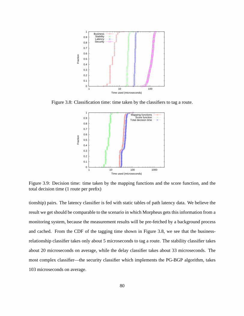
0
0.1
0.2
0.3
0.4
0.5
0.6
0.7
0.8
0.9
1
1 10 100
Fra
ctio
n
Time used (microseconds)
BusinessStabilityLatencySecurity
Figure 3.8: Classification time: time taken by the classifiers to tag a route.
0
0.1
0.2
0.3
0.4
0.5
0.6
0.7
0.8
0.9
1
1 10 100 1000
Fra
ctio
n
Time used (microseconds)
Mapping functionsScore function
Total decision time
Figure 3.9: Decision time: time taken by the mapping functions and the score function, and thetotal decision time (1 route per prefix)
tionship) pairs. The latency classifier is fed with static tables of path latency data. We believe the
result we get should be comparable to the scenario in which Morpheus gets this information from a
monitoring system, because the measurement results will bepre-fetched by a background process
and cached. From the CDF of the tagging time shown in Figure 3.8, we see that the business-
relationship classifier takes only about 5 microseconds to tag a route. The stability classifier takes
about 20 microseconds on average, while the delay classifiertakes about 33 microseconds. The
most complex classifier—the security classifier which implements the PG-BGP algorithm, takes
103 microseconds on average.
80

0
0.1
0.2
0.3
0.4
0.5
0.6
0.7
0.8
0.9
1
10 100 1000
Fra
ctio
n
Time used (microseconds)
MorpheusXORP-BGP
Figure 3.10: Decision time: comparison between Morpheus and XORP-BGP, 20 routes per prefix.
Decision time (one route per prefix):We then benchmark the time taken by the decision process
to calculate the final score for a route (excluding the classification time). Figure 3.9 shows the
CDFs of the two components of the decision time—the mapping functions (one for each classifier)
and the score function, as well as the total time. As we expected, the score function runs very
quickly, taking only 8 microseconds on average. The four mapping functions take 37 microseconds
in total. The total decision time is about 45 microseconds onaverage. In this experiment, the update
generator only sends one update per prefix to the Morpheus server, so there is no tie-breaking
involved in our measurements.
Decision time (multiple alternative routes per prefix): In the next experiment, we compare the
decision time of Morpheus and the out-of-the-box BGP implementation of XORP (XORP-BGP),
when each prefix has multiple alternative routes. We configure both Morpheus and XORP-BGP to
receive 20 identical (except for router IDs) routes per prefix from the update generator. To make a
fair comparison, we configure Morpheus to use router ID to break ties. From Figure 3.10 we can
see Morpheus takes about 54 microseconds on average to select a best route, whereas XORP-BGP
takes an average time of 279 microseconds.
It is not surprising to see that Morpheus takes much less timethan XORP-BGP in selecting best
route when the number of alternative routes is large, because regardless of the number of alternative
81

routes per prefix, Morpheus only needs to compute one score when a new route arrives, whereas
XORP-BGP has to compare the pool of alternative routes for the same prefix all together through
the step-by-step comparisons in the BGP decision process. This also explains why the decision
time of Morpheus has smaller variation, while XORP-BGP’s decision time varies significantly,
ranging from less than 100 microseconds (when there is only asmall number of alternative routes
for a prefix) to over 500 microseconds (when the number becomes large).
Table 3.2: Processing time of the rank-based tie-breaker
10 routes/prefix 20 routes/prefix
10 edge routers 83µs 175µs20 edge routers 138µs 309µs
Time to perform rank-based tie-breaking: Finally we measure the time Morpheus takes to
perform rank-based tie-breaking when multiple alternative routes have the same score. Without
any knowledge about how often and how many routes will end up having the same score, we study
two cases in our experiments: therandom caseand theworst case. In the random case, we assign
every alternative route with a random integer score uniformly selected between 0 and 100. In the
worst case, we let all alternative routes per prefix have the same score. We run eight test cases:
random case/worst case with 10/20 edge routers and with 10/20 routes per prefix. Since in the
four random cases, there is little possibility (i.e., (202 ) · 0.012 = 0.019) that two routes will have the
same final score, leaving the rank-based tie-breaker almostnever used, we list only the average tie-
breaking time of the four worst cases in Table 3.2. As we can see, if all alternative routes happen
to have the same score, the rank-based tie-breaking step will become the performance bottleneck
of Morpheus’ decision process, even in the modest case of 10 routes/prefix with 10 edge routers.
However, such worst case scenario is not likely to happen very often in reality, especially when the
number of alternative routes is relatively large.
82
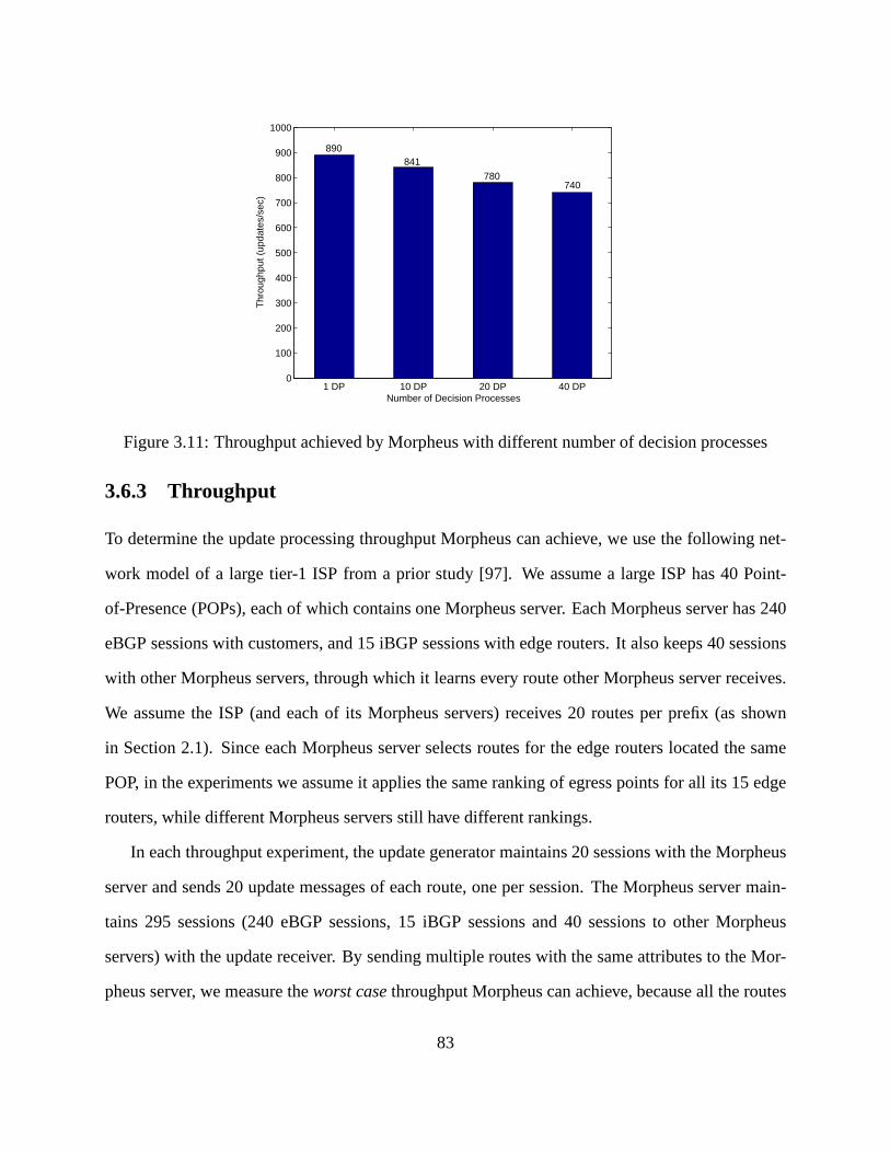
1 DP 10 DP 20 DP 40 DP0
100
200
300
400
500
600
700
800
900
1000
Number of Decision Processes
Thr
ough
put (
upda
tes/
sec)
890841
780740
Figure 3.11: Throughput achieved by Morpheus with different number of decision processes
3.6.3 Throughput
To determine the update processing throughput Morpheus canachieve, we use the following net-
work model of a large tier-1 ISP from a prior study [97]. We assume a large ISP has 40 Point-
of-Presence (POPs), each of which contains one Morpheus server. Each Morpheus server has 240
eBGP sessions with customers, and 15 iBGP sessions with edgerouters. It also keeps 40 sessions
with other Morpheus servers, through which it learns every route other Morpheus server receives.
We assume the ISP (and each of its Morpheus servers) receives20 routes per prefix (as shown
in Section 2.1). Since each Morpheus server selects routes for the edge routers located the same
POP, in the experiments we assume it applies the same rankingof egress points for all its 15 edge
routers, while different Morpheus servers still have different rankings.
In each throughput experiment, the update generator maintains 20 sessions with the Morpheus
server and sends 20 update messages of each route, one per session. The Morpheus server main-
tains 295 sessions (240 eBGP sessions, 15 iBGP sessions and 40 sessions to other Morpheus
servers) with the update receiver. By sending multiple routes with the same attributes to the Mor-
pheus server, we measure theworst casethroughput Morpheus can achieve, because all the routes
83

will have the same score and hence the rank-based tie-breaking step is always performed. Every
throughput experiment runs for a 15-minutes period, and theupdate generator sends updates at the
fastest rate it can get.
Figure 3.11 compares the throughput achieved by Morpheus configured with different number
of decision processes. When Morpheus only runs one decisionprocess, it achieves a sustained
throughput of 890 updates/s. As the number of decision processes increases to 10, 20 and 40,
the achieved throughput decreases slowly to 841, 780 and 740updates/s, respectively. When we
increase the number of decision processes, we assume each customer still subscribes to only one of
them (i.e., only receives one route per prefix). As such, the total number of updates the Morpheus
sends to the update receiver does not increase.
We are satisfied with the throughput our unoptimized prototype achieves, as a large tier-1 ISP
usually receives less than 600 updates/s (95 percentile) [97]. The slow decrease of throughput
as the number of decision processes increases also demonstrates Morpheus’ score-based decision
process design can scale to a large number of different policies.
3.6.4 Memory Requirement
When we compare the memory consumption of Morpheus with XORP-BGP, we find XORP-BGP
consumes 970 MB of memory when loaded with five routes per prefix, as its implementation
stores multiple copies of each route. Therefore, neither the out-of-box XORP-BGP nor our XORP-
based Morpheus prototype were able to load 20 full BGP routing tables with 3.6 GB of memory.
However, the memory footprint of our Morpheus prototype is only 10% larger than that of XORP-
BGP, which is mainly used by the classifiers (largely by the security classifier) and used to store
metadata of routes (tags, scores, etc.). We observe that other BGP implementations consume much
less memory comparing to XORP under the same condition. For example, openbgpd only takes
270 MB to store 20 full BGP routing tables [97]. Our experiment on Quagga [79] shows a memory
footprint of 550 MB with 20 full BGP routing tables. Therefore, we believe that a Morpheus
84

prototype based on a BGP implementation with better memory efficiency will not impose any
memory pressure on a reasonably provisioned server. We alsonote that, unlike router memory,
memory for regular servers is cheap and easy to install.
3.7 Related Work
Previous work proposes to raise the level of abstraction of BGP policy configuration through
network-wide, vendor-neutral specification languages [5,12]. However, we believe new languages
alone are not sufficient to make policy configuration more flexible, because today’s intra-AS rout-
ing architecture and the current BGP decision process both introduce peculiar constraints on the
set of policies that can be realized. In this chapter, we takea fresh approach of “design for con-
figurability” and present a system that supports more flexible routing policies and yet is easier to
configure.
Several recent studies on the Routing Control Platform (RCP) [33] advocate moving the BGP
control plane of a single AS to a small set of servers that select routes on behalf of the routers [15,
96, 97, 6]. The prototype systems in [15] and [97] demonstrate that a logically-centralized control
plane running on commodity hardware can be scalable, reliable, and fast enough to drive BGP rout-
ing decisions in a large ISP backbone. However, the system in[15] simply mimics the standard
BGP decision process, without expanding the space of realizable policies. While [96] and [97]
support more flexible alternatives to today’s hot-potato routing, these systems do not create an
extensible framework for realizing flexible policies with trade-offs amongst policy objectives, or
support multiple different policies simultaneously. Theydo not revisit the convoluted BGP config-
uration interface either. These are the main contributionsof our Morpheus design.
85
3.8 Summary
This chapter presents the design, implementation and evaluation of Morpheus, a routing control
platform that enables a single ISP to realize many useful routing policies that are infeasible today
without changing its routers. The design of the Morpheus server separates route classification from
route selection, which enables network operators to easilydefine new policy objectives, imple-
ment independent objective classifiers, and make flexible trade-offs between objectives. Morpheus
allows large ISPs to capitalize on their path diversity and provide customer-specific routes as a
value-added service. It also enables an ISP to allow its customers to influence its routing policies
through a simple and intuitive configuration interface. Ourexperiments show that Morpheus can
support a large number of different policies simultaneously while handling the high rate of BGP
updates experienced in large ISPs.
86
Chapter 4
VROOM: Live (Virtual) Router Migration
as a Network-Management Primitive
4.1 Introduction
In Chapters 2 and 3, we focused on how an ISP can realize flexible and customizable routing poli-
cies through intuitive configuration interface. To ensure quality of service, besides suchactive
management of routing in its network, an ISP also needs to make sure that other network manage-
ment operations introduce as little disruption to routing as possible. However, from routine tasks
such as planned maintenance to the less-frequent deployment of new protocols, network operators
struggle to provide seamless service in the face of changes to the underlying network.
Handling change is difficult because each change to the physical infrastructure requires a cor-
responding modification to the logical configuration of the routers—such as reconfiguring the tun-
able parameters in the routing protocols.Logical refers to IP packet-forwarding functions, while
physicalrefers to the physical router equipment (such as line cards and the CPU) that enables
these functions. Any inconsistency between the logical andphysical configurations can lead to
unexpected reachability or performance problems. Furthermore, because of today’s tight coupling
87

between the physical and logical topologies, logical-layer changes are sometimes used purely as a
tool to handle physical changes more gracefully. A classic example is increasing the link weights
in Interior Gateway Protocols to “cost out” a router in advance of planned maintenance [93]. In
this case, a change in the logical topology isnot the goal, rather it is the indirect tool available to
achieve the task at hand, and it does so with potential negative side effects.
In this chapter, we argue that breaking the tight coupling between physical and logical con-
figurations can provide asingle, general abstraction that simplifies network management. Specifi-
cally, we propose VROOM (Virtual ROuters On the Move), a new network-management primitive
where virtual routers can move freely from one physical router to another. In VROOM, physical
routers merely serve as the carrier substrate on which the actual virtual routers operate. VROOM
can migrate a virtual router to a different physical router without disrupting the flow of traffic
or changing the logical topology, obviating the need to reconfigure the virtual routers while also
avoiding routing-protocol convergence delays. For example, if a physical router must undergo
planned maintenance, the virtual routers could move (in advance) to another physical router in the
same Point-of-Presence (PoP). In addition, edge routers can move from one location to another by
virtually re-homing the links that connect to neighboring domains.
Realizing these objectives presents several challenges: (i) migratable routers: to make a (vir-
tual) router migratable, its “router” functionality must be separable from the physical equipment
on which it runs; (ii)minimal outages:to avoid disrupting user traffic or triggering routing pro-
tocol reconvergence, the migration should cause no or minimal packet loss; (iii)migratable links:
to keep the IP-layer topology intact, the links attached to amigrating router must “follow” it to its
new location. Fortunately, the third challenge is addressed by recent advances in transport-layer
technologies, as discussed in Section 4.2. Our goal, then, is to migrate router functionality from
one piece of equipment to another without disrupting the IP-layer topology or the data traffic it
carries, and without requiring router reconfiguration.
On the surface, virtual router migration might seem like a straight-forward extention to existing
88

virtual machine migration techniques. This would involve copying the virtual router image (includ-
ing routing-protocol binaries, configuration files and data-plane state) to the new physical router
and freezing the running processes before copying them as well. The processes and data-plane
state would then be restored on the new physical router and associated with the migrated links.
However, the delays in completing all of these steps would cause unacceptable disruptions for
both the data traffic and the routing protocols. For virtual router migration to be viable in practice,
packet forwarding should not be interrupted, not even temporarily. In contrast, the control plane
can tolerate brief disruptions, since routing protocols have their own retransmission mechansisms.
Still, the control plane must restart quickly at the new location to avoid losing protocol adjacencies
with other routers and to minimize delay in responding to unplanned network events.
In VROOM, we minimize disruption by leveraging the separation of the control and data planes
in modern routers. We introduce adata-plane hypervisor—a migration-aware interface between
the control and data planes. This unified interface allows usto support migration between physical
routers with different data-plane technologies. VROOM migrates only the control plane, while
continuing to forward traffic through the old data plane. Thecontrol plane can start running at the
new location, and populate the new data plane while updatingthe old data plane in parallel. During
the transition period, the old router redirects routing-protocol traffic to the new location. Once the
data plane is fully populated at the new location, link migration can begin. The two data planes
operate simultaneously for a period of time to facilitate asynchronous migration of the links.
To demonstrate the generality of our data-plane hypervisor, we present two prototype VROOM
routers—one with a software data plane (in the Linux kernel)and the other with a hardware data
plane (using a NetFPGA card [72]). Each virtual router runs the Quagga routing suite [79] in an
OpenVZ container [73]. Our software extensions consist of three main modules that (i) separate
the forwarding tables from the container contexts, (ii) push the forwarding-table entries generated
by Quagga into the separate data plane, and (iii) dynamically bind the virtual interfaces and for-
warding tables. Our system supports seamless live migration of virtual routers between the two
89

data-plane platforms. Our experiments show that virtual router migration causes no packet loss
or delay when the hardware data plane is used, and at most a fewseconds of delay in processing
control-plane messages.
The remainder of the chapter is structured as follows. Section 4.2 presents background on
flexible transport networks and an overview of related work.Next, Section 4.3 discusses how
router migration would simplify existing network management tasks, such as planned maintenance
and service deployment, while also addressing emerging challenges like power management. We
present the VROOM architecture in Section 4.4, followed by the implementation and evaluation
in Sections 4.5 and 4.6, respectively. We discuss migrationscheduling in Section 4.7 and related
work in Section 4.8, before summarizing this chapter in Section 4.9.
4.2 Background: Flexible Link Migration
One of the fundamental requirements of VROOM is “link migration”, i.e., the links of a virtual
router should “follow” its migration from one physical nodeto another. This is made possible by
emerging transport network technologies.
In its most basic form, a link at the IP layer corresponds to a direct physical link (e.g., a ca-
ble), making link migration hard as it involves physically moving link end point(s). However,
in practice, what appears as a direct link at the IP layer often corresponds to a series of con-
nections through different network elements at the transport layer. For example, in today’s ISP
backbones, “direct” physical links are typically realizedby optical transport networks, where an
IP link corresponds to a circuit traversing multiple optical switches [22, 107]. Recent advances in
programmable transport networks[22, 4] allow physical links between routers to be dynamically
set up and torn down. For example, as shown in Figure 4.1(a), the link between physical routers A
and B is switched through a programmable transport network.By signaling the transport network,
the same physical port on router A can be connected to router Cafter an optical path switch-over.
90
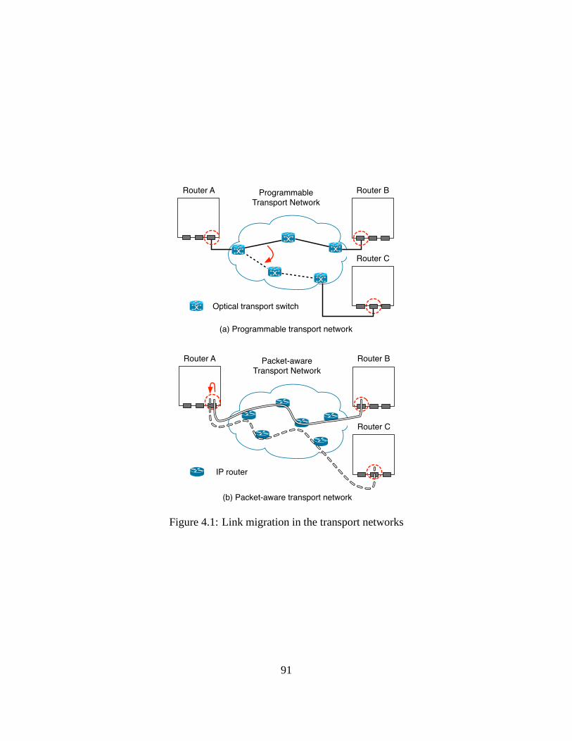
Router A ProgrammableTransport Network
Router B
Router C
Optical transport switch
(a) Programmable transport network
Router A Packet-awareTransport Network
Router B
Router C
IP router
(b) Packet-aware transport network
Figure 4.1: Link migration in the transport networks
91

Such path switch-over at the transport layer can be done efficiently, e.g., sub-nanosecond optical
switching time has been reported [82]. Furthermore, such switching can be performed across a
wide-area network of transport switches, which enables inter-POP link migration.
In addition tocore linkswithin an ISP, we also want to migrateaccess linksconnecting cus-
tomer edge (CE) routers and provider edge (PE) routers, where only the PE end of the links are
under the ISP’s control. Historically, access links correspond to a path in the underlying access
network, such as a T1 circuit in a time-division multiplexing (TDM) access network. In such cases,
the migration of an access link can be accomplished in similar fashion to the mechanism shown
in Figure 4.1(a), by switching to a new circuit at the switch directly connected to the CE router.
However, in traditional circuit-switched access networks, a dedicated physical port on a PE router
is required to terminate each TDM circuit. Therefore, if allports on a physical PE router are in
use, it will not be able to accommodate more virtual routers.Fortunately, as Ethernet emerges as
an economical and flexible alternative to legacy TDM services, access networks are evolving to
packet-awaretransport networks [3]. This trend offers important benefits for VROOM by elimi-
nating the need for per-customer physical ports on PE routers. In a packet-aware access network
(e.g., a virtual private LAN service access network), each customer access port is associated with
a label, or a “pseudo wire” [14], which allows a PE router to support multiple logical access links
on the same physical port. The migration of a pseudo-wire access link involves establishing a new
pseudo wire and switching to it at the multi-service switch [3] adjacent to the CE.
Unlike conventional ISP networks, some networks are realized as overlays on top of other
ISPs’ networks. Examples include commercial “Carrier Supporting Carrier (CSC)” networks [24],
and VINI, a research virtual network infrastructure overlaid on top of National Lambda Rail and
Internet2 [99]. In such cases, a single-hop link in the overlay network is actually a multi-hop path
in the underlying network, which can be an MPLS VPN (e.g., CSC) or an IP network (e.g., VINI).
Link migration in an MPLS transport network involves switching over to a newly established label
switched path (LSP). Link migration in an IP network can be done by changing the IP address of
92

the tunnel end point.
4.3 Network Management Tasks
In this section, we present three case studies of the applications of VROOM. We show that the
separation between physical and logical, and the router migration capability enabled by VROOM,
can greatly simplify existing network-management tasks. It can also provide network-management
solutions to other emerging challenges. We explain why the existing solutions (in the first two
examples) are not satisfactory and outline the VROOM approach to addressing the same problems.
4.3.1 Planned Maintenance
Planned maintenance is a hidden fact of life in every network. However, the state-of-the-art prac-
tices are still unsatisfactory. For example, software upgrades today still require rebooting the router
and re-synchronizing routing protocol states from neighbors (e.g., BGP routes), which can lead to
outages of 10-15 minutes [4]. Different solutions have beenproposed to reduce the impact of
planned maintenance on network traffic, such as “costing out” the equipment in advance. Another
example is the RouterFarm approach of removing the static binding between customers and ac-
cess routers to reduce service disruption time while performing maintenance on access routers [4].
However, we argue that neither solution is satisfactory, since maintenance ofphysicalrouters still
requires changes to thelogical network topology, and requires (often human interactive) reconfig-
urations and routing protocol reconvergence. This usuallyimplies more configuration errors [60]
and increased network instability.
We performed an analysis of planned-maintenance events conducted in a Tier-1 ISP backbone
over a one-week period. Due to space limitations, we only mention the high-level results that
are pertinent to VROOM here. Our analysis indicates that, among all the planned-maintenance
events that have undesirable network impact today (e.g., routing protocol reconvergence or data-
93

plane disruption), 70% could be conducted without any network impact if VROOM were used.
(This number assumes migration between routers with control planes of like kind. With more so-
phisticated migration strategies, e.g., where a “control-plane hypervisor” allows migration between
routers with different control plane implementations, thenumber increases to 90%.) These promis-
ing numbers result from the fact that most planned-maintenance events were hardware related and,
as such, did not intend to make any longer-term changes to thelogical-layer configurations.
To perform planned maintenance tasks in a VROOM-enabled network, network administrators
can simply migrate all the virtual routers running on a physical router to other physical routers
before doing maintenance and migrate them back afterwards as needed, without ever needing to
reconfigure any routing protocols or worry about traffic disruption or protocol reconvergence.
4.3.2 Service Deployment and Evolution
Deploying new services, like IPv6 or IPTV, is the life-bloodof any ISP. Yet, ISPs must exercise
caution when deploying these new services. First, they mustensure that the new services do not
adversely impact existing services. Second, the necessarysupport systems need to be in place
before services can be properly supported. (Support systems include configuration management,
service monitoring, provisioning, and billing.) Hence, ISPs usually start with a small trial running
in a controlled environment on dedicated equipment, supporting a few early-adopter customers.
However, this leads to a “success disaster” when the servicewarrants wider deployment. The
ISP wants to offer seamless service to its existing customers, and yet also restructure their test
network, or move the service onto a larger network to serve a larger set of customers. This “trial
system success” dilemma is hard to resolve if thelogical notion of a “network node” remains
bound to a specificphysicalrouter.
VROOM provides a simple solution by enabling network operators to freely migrate virtual
routers from the trial system to the operational backbone. Rather than shutting down the trial
service, the ISP can continue supporting the early-adoptercustomers while continuously growing
94

the trial system, attracting new customers, and eventuallyseamlessly migrating the entire service
to the operational network.
ISPs usually deploy such service-oriented routers as closeto their customers as possible, in
order to avoid backhaul traffic. However, as the services grow, the geographical distribution of
customers may change over time. With VROOM, ISPs can easily reallocate the routers to adapt to
new customer demands.
4.3.3 Power Savings
VROOM not only provides simple solutions to conventional network-management tasks, but also
enables new solutions to emerging challenges such as power management. It was reported that
in 2000 the total power consumption of the estimated 3.26 million routers in the U.S. was about
1.1 TWh (Tera-Watt hours) [83]. This number was expected to grow to 1.9 to 2.4TWh in the
year 2005 [83], which translates into an annual cost of about178-225 million dollars [78]. These
numbers do not include the power consumption of the requiredcooling systems.
Although designing energy-efficient equipment is clearly an important part of the solution [52],
we believe that network operators can alsomanagea network in a more power-efficient manner.
Previous studies have reported that Internet traffic has a consistent diurnal pattern caused by human
interactive network activities. However, today’s routersare surprisingly power-insensitive to the
traffic loads they are handling—an idle router consumes over90% of the power it requires when
working at maximum capacity [17]. We argue that, with VROOM,the variations in daily traffic
volume can be exploited to reduce power consumption. Specifically, the size of the physical net-
work can be expanded and shrunk according to traffic demand, by hibernating or powering down
the routers that are not needed. The best way to do this today would be to use the “cost-out/cost-in”
approach, which inevitably introduces configuration overhead and performance disruptions due to
protocol reconvergence.
VROOM provides a cleaner solution: as the network traffic volume decreases at night, virtual
95
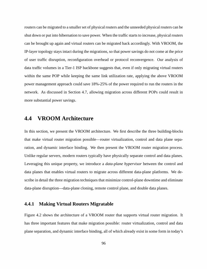
routers can be migrated to a smaller set of physical routers and the unneeded physical routers can be
shut down or put into hibernation to save power. When the traffic starts to increase, physical routers
can be brought up again and virtual routers can be migrated back accordingly. With VROOM, the
IP-layer topology stays intact during the migrations, so that power savings do not come at the price
of user traffic disruption, reconfiguration overhead or protocol reconvergence. Our analysis of
data traffic volumes in a Tier-1 ISP backbone suggests that, even if only migrating virtual routers
within the same POP while keeping the same link utilization rate, applying the above VROOM
power management approach could save 18%-25% of the power required to run the routers in the
network. As discussed in Section 4.7, allowing migration across different POPs could result in
more substantial power savings.
4.4 VROOM Architecture
In this section, we present the VROOM architecture. We first describe the three building-blocks
that make virtual router migration possible—router virtualization, control and data plane sepa-
ration, and dynamic interface binding. We then present the VROOM router migration process.
Unlike regular servers, modern routers typically have physically separate control and data planes.
Leveraging this unique property, we introduce adata-plane hypervisorbetween the control and
data planes that enables virtual routers to migrate across different data-plane platforms. We de-
scribe in detail the three migration techniques that minimize control-plane downtime and eliminate
data-plane disruption—data-plane cloning, remote control plane, and double data planes.
4.4.1 Making Virtual Routers Migratable
Figure 4.2 shows the architecture of a VROOM router that supports virtual router migration. It
has three important features that make migration possible:router virtualization, control and data
plane separation, and dynamic interface binding, all of which already exist in some form in today’s
96

Physical Router
Substrate
Dynamic interface binding
Physical interface
(2)
(2)
Data Plane
Control Plane
Virtual Router
Control Plane
Virtual Router
Control Plane
Virtual Router
Data Plane
Data Plane
(1)
Data-plane hypervisor(1)
Tunnel interface
Figure 4.2: The architecture of a VROOM router
high-end commercial routers.
Router Virtualization: A VROOM router partitions the resources of a physical routerto support
multiplevirtual router instances. Each virtual router runs independently with itsown control plane
(e.g., applications, configurations, routing protocol instances and routing information base (RIB))
and data plane (e.g., interfaces and forwarding information base (FIB)). Suchrouter virtualization
support is already available in some commercial routers [25, 57]. The isolation between virtual
routers makes it possible to migrate one virtual router without affecting the others.
Control and Data Plane Separation: In a VROOM router, the control and data planes run in
separateenvironments. As shown in Figure 4.2, the control planes of virtual routers are hosted in
separate “containers” (or “virtual environments”), whiletheir data planes reside in thesubstrate,
where each data plane is kept in separate data structures with its own state information, such as FIB
entries and access control lists (ACLs). Similar separation of control and data planes already exists
in today’s commercial routers, with control plane running on the CPU(s) and main memory, while
the data plane runs on line cards that have their own computing power (for packet forwarding) and
memory (to hold the FIBs). This separation allows VROOM to migrate the control and data planes
97
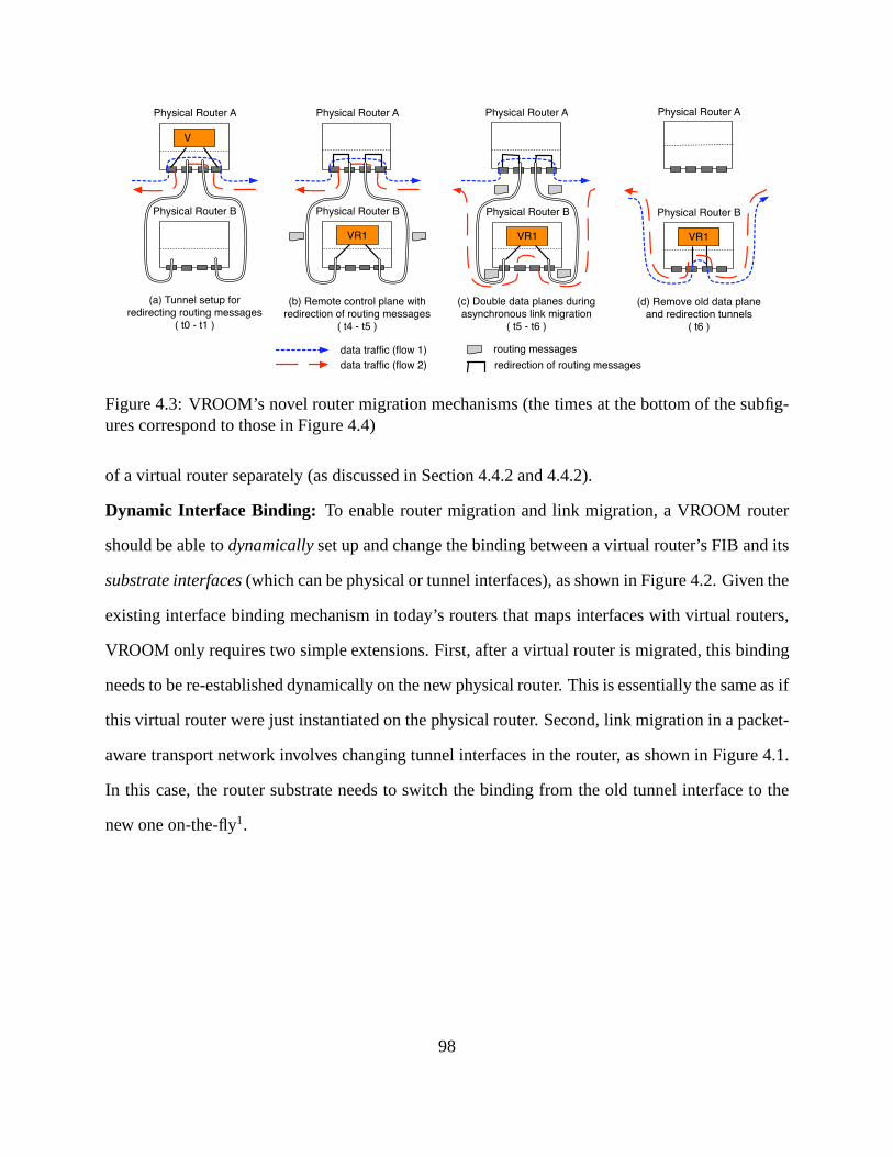
V
Physical Router A
Physical Router B
VR1
Physical Router A Physical Router A
data traffic (flow 1)
Physical Router A
routing messages
(a) Tunnel setup for redirecting routing messages
( t0 - t1 )
(b) Remote control plane withredirection of routing messages
( t4 - t5 )
(c) Double data planes duringasynchronous link migration
( t5 - t6 )
(d) Remove old data plane and redirection tunnels
( t6 )
data traffic (flow 2)
Physical Router B
VR1
Physical Router B
VR1
Physical Router B
redirection of routing messages
Figure 4.3: VROOM’s novel router migration mechanisms (thetimes at the bottom of the subfig-ures correspond to those in Figure 4.4)
of a virtual router separately (as discussed in Section 4.4.2 and 4.4.2).
Dynamic Interface Binding: To enable router migration and link migration, a VROOM router
should be able todynamicallyset up and change the binding between a virtual router’s FIB and its
substrate interfaces(which can be physical or tunnel interfaces), as shown in Figure 4.2. Given the
existing interface binding mechanism in today’s routers that maps interfaces with virtual routers,
VROOM only requires two simple extensions. First, after a virtual router is migrated, this binding
needs to be re-established dynamically on the new physical router. This is essentially the same as if
this virtual router were just instantiated on the physical router. Second, link migration in a packet-
aware transport network involves changing tunnel interfaces in the router, as shown in Figure 4.1.
In this case, the router substrate needs to switch the binding from the old tunnel interface to the
new one on-the-fly1.
98
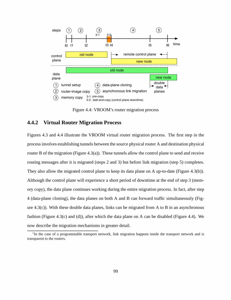
router-image copy
memory copy
asynchronous link migration
data-plane cloning
stall-and-copy (control plane downtime)
t2 timet0 t1 t3 t5 t6
old nodecontrol
plane
data
plane
new node
old node
new node
remote control plane
double data
planes2
1 2 3 4 5
1 tunnel setup
3
4
5
pre-copy
3-1 3-2
3-1:3-2:
t4
steps
Figure 4.4: VROOM’s router migration process
4.4.2 Virtual Router Migration Process
Figures 4.3 and 4.4 illustrate the VROOM virtual router migration process. The first step in the
process involves establishing tunnels between the source physical router A and destination physical
router B of the migration (Figure 4.3(a)). These tunnels allow the control plane to send and receive
routing messages after it is migrated (steps 2 and 3) but before link migration (step 5) completes.
They also allow the migrated control plane to keep its data plane on A up-to-date (Figure 4.3(b)).
Although the control plane will experience a short period ofdowntime at the end of step 3 (mem-
ory copy), the data plane continues working during the entire migration process. In fact, after step
4 (data-plane cloning), the data planes on both A and B can forward traffic simultaneously (Fig-
ure 4.3(c)). With these double data planes, links can be migrated from A to B in an asynchronous
fashion (Figure 4.3(c) and (d)), after which the data plane on A can be disabled (Figure 4.4). We
now describe the migration mechanisms in greater detail.
1In the case of a programmable transport network, link migration happens inside the transport network and istransparent to the routers.
99

Control-Plane Migration
Two things need to be taken care of when migrating the controlplane: therouter image, such
as routing-protocol binaries and network configuration files, and thememory, which includes the
states of all the running processes. When copying the routerimage and memory, it is desirable to
minimize the total migration time, and more importantly, tominimize the control-plane downtime
(i.e., the time between when the control plane is check-pointed on the source node and when
it is restored on the destination node). This is because, although routing protocols can usually
tolerate a brief network glitch using retransmission (e.g., BGP uses TCP retransmission, while
OSPF uses its own reliable retransmission mechanism), a long control-plane outage can break
protocol adjacencies and cause protocols to reconverge.
We now describe how VROOM leverages virtual machine (VM) migration techniques to mi-
grate the control plane in steps 2 (router-image copy) and 3 (memory copy) of its migration process,
as shown in Figure 4.4.
Unlike general-purpose VMs that can potentially be runningcompletely different programs,
virtual routers from the same vendor run the same (usually small) set of programs (e.g., routing
protocol suites). VROOM assumes that the same set of binaries are already available on every
physical router. Before a virtual router is migrated, the binaries are locally copied to its file system
on the destination node. Therefore, only the router configuration files need to be copied over the
network, reducing the total migration time (as local-copy is usually faster than network-copy).
The simplest way to migrate the memory of a virtual router is to check-point the router, copy the
memory pages to the destination, and restore the router, a.k.a. stall-and-copy[73]. This approach
leads to downtime that is proportional to the memory size of the router. A better approach is to add
an iterativepre-copyphase before the final stall-and-copy [27], as shown in Figure 4.4. All pages
are transferred in the first round of the pre-copy phase, and in the following rounds, only pages
that were modified during the previous round are transferred. This pre-copy technique reduces
the number of pages that need to be transfered in the stall-and-copy phase, reducing the control
100

plane downtime of the virtual router (i.e., the control plane is only “frozen” between t3 and t4 in
Figure 4.4).
Data-Plane Cloning
The control-plane migration described above could be extended to migrate the data plane, i.e., copy
all data-plane states over to the new physical node. However, this approach has two drawbacks.
First, copying the data-plane states (e.g., FIB and ACLs) isunnecessary and wasteful, because
the information that is used to generate these states (e.g.,RIB and configuration files) is already
available in the control plane. Second, copying the data-plane state directly can be difficult if the
source and destination routers use different data-plane technologies. For example, some routers
may use TCAM (ternary content-addressable memory) in theirdata planes, while others may use
regular SRAM. As a result, the data structures that hold the state may be different.
VROOM formalizes the interface between the control and dataplanes by introducing adata-
plane hypervisor, which allows a migrated control plane to re-instantiate the data plane on the
new platform, a process we calldata-plane cloning. That is, only the control plane of the router
is actually migrated. Once the control plane is migrated to the new physical router, itclonesits
original data plane by repopulating the FIB using its RIB andreinstalling ACLs and other data-
plane states2 through the data-plane hypervisor (as shown in Figure 4.2).The data-plane hypervisor
provides a unified interface to the control plane that hides the heterogeneity of the underlying data-
plane implementations, enabling virtual routers to migrate between different types of data planes.
Remote Control Plane
As shown in Figure 4.3(b), after VR1’s control plane is migrated from A to B, the natural next steps
are to repopulate (clone) the data plane on B and then migratethe links from A to B. Unfortunately,
2Data dynamically collected in the old data plane (such as NetFlow) can be copied and merged with the new one.Other path-specific statistics (such as queue length) will be reset as the previous results are no longer meaningful oncethe physical path changes.
101

the creation of the new data plane can not be done instantaneously, primarily due to the time it
takes to install FIB entries. Installing one FIB entry typically takes between one hundred and a
few hundred microseconds [13]; therefore, installing the full Internet BGP routing table (about
250k routes) could take over 20 seconds. During this period of time, although data traffic can still
be forwarded by the old data plane on A, all the routing instances in VR1’s control plane can no
longer send or receive routing messages. The longer the control plane remains unreachable, the
more likely it will lose its protocol adjacencies with its neighbors.
To overcome this dilemma, A’s substrate starts redirectingall the routing messages destined
to VR1 to B at the end of the control-plane migration (time t4 in Figure 4.4). This is done by
establishing a tunnel between A and B for each of VR1’s substrate interfaces. To avoid introducing
any additional downtime in the control plane, these tunnelsare established before the control-plane
migration, as shown in Figure 4.3(a). With this redirectionmechanism, VR1’s control plane not
only can exchange routing messages with its neighbors, it can also act as theremote control plane
for its old data plane on A and continue to update the old FIB when routing changes happen.
Double Data Planes
In theory, at the end of the data-plane cloning step, VR1 can switch from the old data plane on A to
the new one on B by migrating all its links from A to B simultaneously. However, performing accu-
rate synchronous link migration across all the links is challenging, and could significantly increase
the complexity of the system (because of the need to implement a synchronization mechanism).
Fortunately, because VR1 hastwo data planes ready to forward traffic at the end of the data-
plane cloning step (Figure 4.4), the migration of its links does not need to happen all at once.
Instead, each link can be migrated independent of the others, in an asynchronous fashion, as shown
in Figure 4.3(c) and (d). First, router B creates a newoutgoinglink to each of VR1’s neighbors,
while all data traffic continues to flow through router A. Then, the incominglinks can be safely
migrated asynchronously, with some traffic starting to flow through router B while the remaining
102
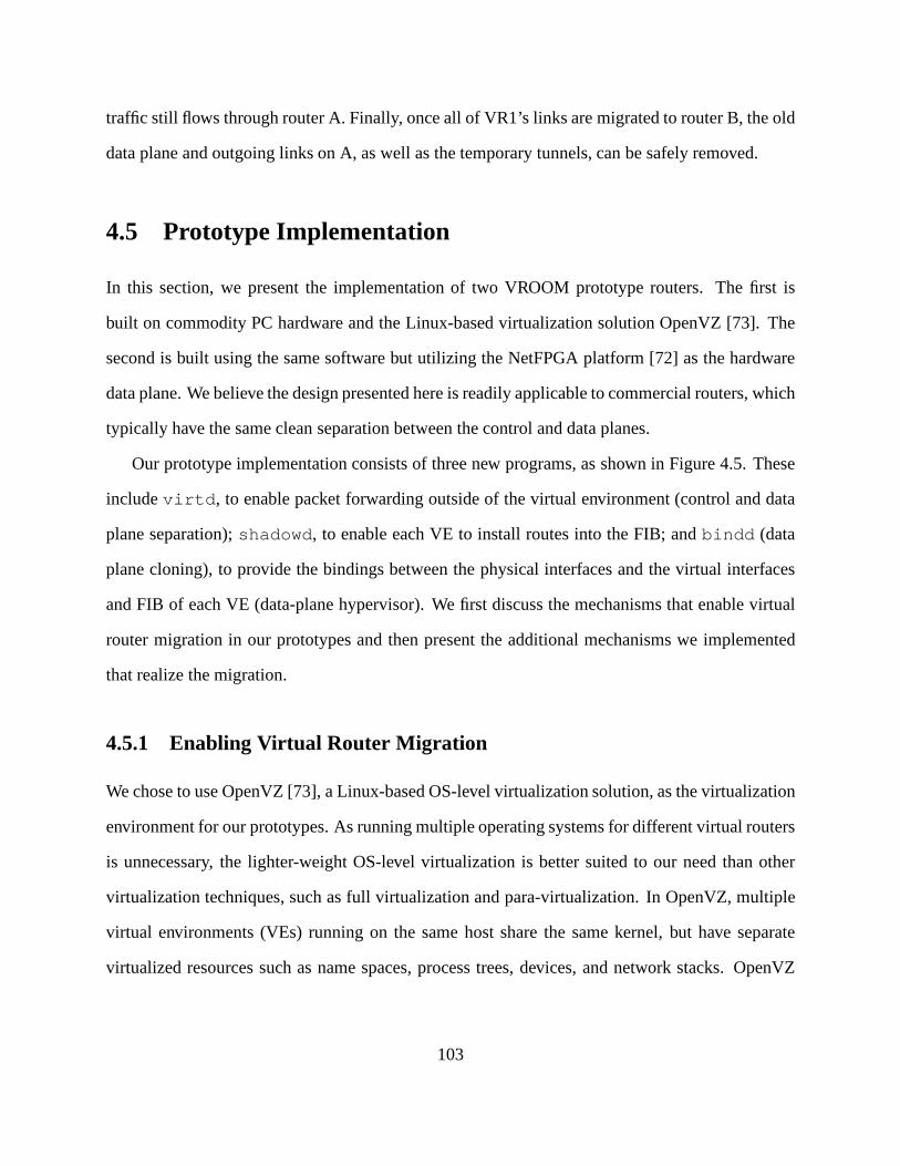
traffic still flows through router A. Finally, once all of VR1’s links are migrated to router B, the old
data plane and outgoing links on A, as well as the temporary tunnels, can be safely removed.
4.5 Prototype Implementation
In this section, we present the implementation of two VROOM prototype routers. The first is
built on commodity PC hardware and the Linux-based virtualization solution OpenVZ [73]. The
second is built using the same software but utilizing the NetFPGA platform [72] as the hardware
data plane. We believe the design presented here is readily applicable to commercial routers, which
typically have the same clean separation between the control and data planes.
Our prototype implementation consists of three new programs, as shown in Figure 4.5. These
includevirtd, to enable packet forwarding outside of the virtual environment (control and data
plane separation);shadowd, to enable each VE to install routes into the FIB; andbindd (data
plane cloning), to provide the bindings between the physical interfaces and the virtual interfaces
and FIB of each VE (data-plane hypervisor). We first discuss the mechanisms that enable virtual
router migration in our prototypes and then present the additional mechanisms we implemented
that realize the migration.
4.5.1 Enabling Virtual Router Migration
We chose to use OpenVZ [73], a Linux-based OS-level virtualization solution, as the virtualization
environment for our prototypes. As running multiple operating systems for different virtual routers
is unnecessary, the lighter-weight OS-level virtualization is better suited to our need than other
virtualization techniques, such as full virtualization and para-virtualization. In OpenVZ, multiple
virtual environments (VEs) running on the same host share the same kernel, but have separate
virtualized resources such as name spaces, process trees, devices, and network stacks. OpenVZ
103
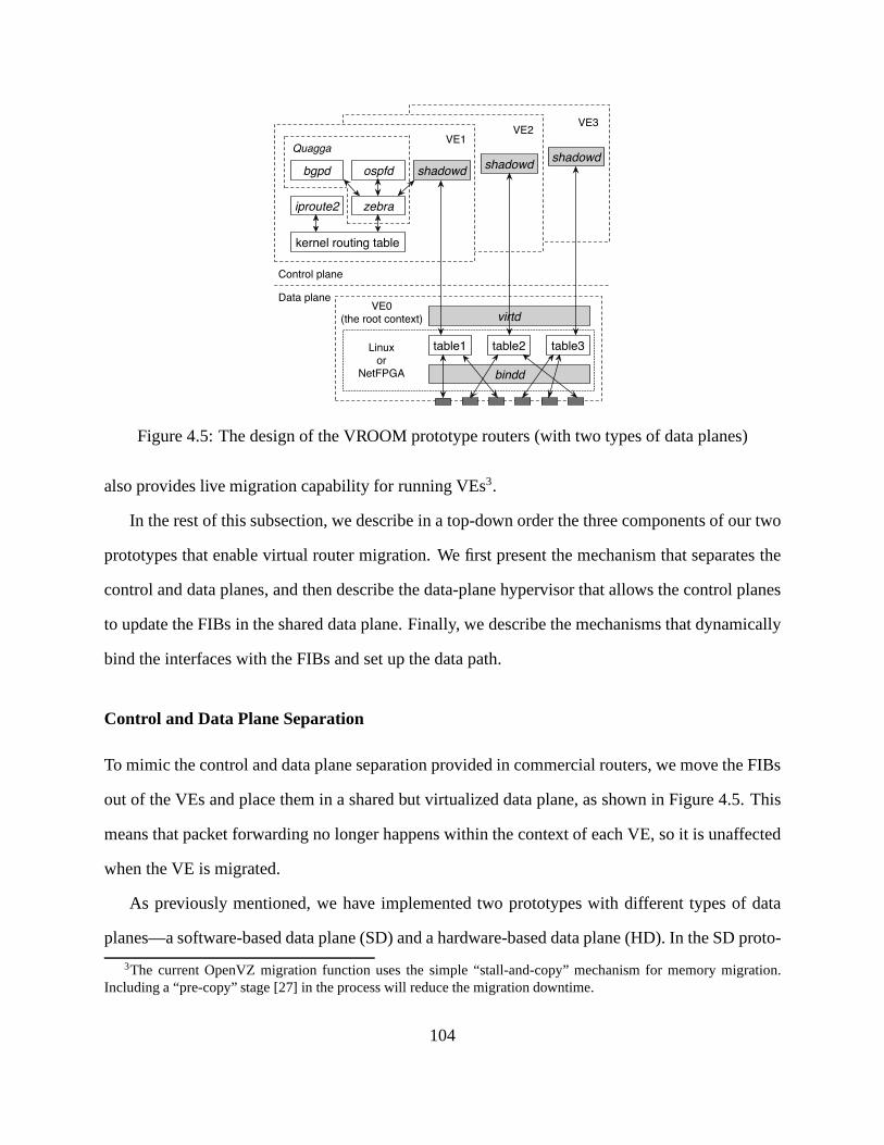
zebra
Quagga
kernel routing table
iproute2
bgpd ospfd shadowd
VE1
shadowd
VE2
shadowd
VE3
virtd
Control plane
Data plane
table1 table2 table3
VE0(the root context)
bindd
Linuxor
NetFPGA
Figure 4.5: The design of the VROOM prototype routers (with two types of data planes)
also provides live migration capability for running VEs3.
In the rest of this subsection, we describe in a top-down order the three components of our two
prototypes that enable virtual router migration. We first present the mechanism that separates the
control and data planes, and then describe the data-plane hypervisor that allows the control planes
to update the FIBs in the shared data plane. Finally, we describe the mechanisms that dynamically
bind the interfaces with the FIBs and set up the data path.
Control and Data Plane Separation
To mimic the control and data plane separation provided in commercial routers, we move the FIBs
out of the VEs and place them in a shared but virtualized data plane, as shown in Figure 4.5. This
means that packet forwarding no longer happens within the context of each VE, so it is unaffected
when the VE is migrated.
As previously mentioned, we have implemented two prototypes with different types of data
planes—a software-based data plane (SD) and a hardware-based data plane (HD). In the SD proto-
3The current OpenVZ migration function uses the simple “stall-and-copy” mechanism for memory migration.Including a “pre-copy” stage [27] in the process will reducethe migration downtime.
104

type router, the data plane resides in the root context (or “VE0”) of the system and uses the Linux
kernel for packet forwarding. Since the Linux kernel (2.6.18) supports 256 separate routing tables,
the SD router virtualizes its data plane by associating eachVE with a different kernel routing table
as its FIB.
In the HD router implementation, we use the NetFPGA platformconfigured with the reference
router provided by Stanford [72]. The NetFPGA card is a 4-port gigabit ethernet PCI card with a
Virtex 2-Pro FPGA on it. With the NetFPGA as the data plane, packet forwarding in the HD router
does not use the host CPU, thus more closely resembling commercial router architectures. The
NetFPGA reference router does not currently support virtualization. As a result, our HD router
implementation is currently limited to only one virtual router per physical node.
Data-Plane Hypervisor
As explained in Section 4.4, VROOM extends the standard control plane/data plane interface to a
migration-aware data-plane hypervisor. Our prototype presents a rudimentary data-plane hypervi-
sor implementation which only supports FIB updates. (A full-fledged data-plane hypervisor would
also allow the configuration of other data plane states.) We implemented thevirtd program as
the data-plane hypervisor.virtd runs in the VE0 and provides an interface for virtual routersto
install/remove routes in the shared data plane, as shown in Figure 4.5. We also implemented the
shadowd program that runs inside each VE and pushes route updates from the control plane to
the FIB throughvirtd.
We run the Quagga routing software suite [79] as the control plane inside each VE. Quagga
supports many routing protocols, including BGP and OSPF. Inaddition to the included protocols,
Quagga provides an interface inzebra, its routing manager, to allow the addition of new protocol
daemons. We made use of this interface to implementshadowd as a client ofzebra. zebra
provides clients with both the ability to notifyzebra of route changes and to be notified of route
changes. Asshadowd is not a routing protocol but simply a shadowing daemon, it uses only
105

the route redistribution capability. Through this interface,shadowd is notified of any changes
in the RIB and immediately mirrors them tovirtd using remote procedure calls (RPCs). Each
shadowd instance is configured with a unique ID (e.g., the ID of the virtual router), which is in-
cluded in every message it sends tovirtd. Based on this ID,virtd can correctly install/remove
routes in the corresponding FIB upon receiving updates froma shadowd instance. In the SD
prototype, this involves using the Linuxiproute2utility to set a routing table entry. In the HD
prototype, this involves using the device driver to write toregisters in the NetFPGA.
Dynamic Interface Binding
With the separation of control and data planes, and the sharing of the same data plane among
multiple virtual routers, the data path of each virtual router must be set up properly to ensure that
(i) data packets can be forwarded according to the right FIB,and (ii) routing messages can be
delivered to the right control plane.
We implemented thebindd program that meets these requirements by providing two main
functions. The first is to set up the mapping between a virtualrouter’s substrate interfaces and its
FIB after the virtual router is instantiated or migrated, toensure correct packet forwarding. (Note
that a virtual router’s substrate interface could be eithera dedicated physical interface or a tunnel
interface that shares the same physical interface with other tunnels.) In the SD prototype,bindd
establishes this binding by using the routing policy management function (i.e., “ip rule”) provided
by the Linuxiproute2utility. As previously mentioned, the HD prototype is currently limited to a
single table. Once NetFPGA supports virtualization, a mechanism similar to the “ip rule” function
can be used to bind the interfaces with the FIBs.
The second function ofbindd is to bind the substrate interfaces with the virtual interfaces of
the control plane. In both prototypes, this binding is achieved by connecting each pair of substrate
and virtual interfaces to a different bridge using the Linuxbrctl utility. In the HD prototype, each
of the four physical ports on the NetFPGA is presented to Linux as a separate physical interface, so
106

packets destined to the control plane of a local VE are passedfrom the NetFPGA to Linux through
the corresponding interface.
4.5.2 Realizing Virtual Router Migration
The above mechanisms set the foundation for VROOM virtual router migration in the OpenVZ
environment. We now describe the implementations of data-plane cloning, remote control plane,
and double data planes.
Although migration is transparent to the routing processesrunning in the VE,shadowd needs
to be notified at the end of the control plane migration in order to start the “data plane cloning”. We
implemented a function inshadowd that, when called, triggersshadowd to requestzebra to
resend all the routes and then push them down tovirtd to repopulate the FIB. Note thatvirtd
runs on a fixed (private) IP address and a fixed port on each physical node. Therefore, after a
virtual router is migrated to a new physical node, the route updates sent by itsshadowd can be
seamlessly routed to the localvirtd instance on the new node.
To enable a migrated control plane to continue updating the old FIB (i.e., to act as a “remote
control plane”), we implemented invirtd the ability to forward route updates to anothervirtd
instance using the same RPC mechanism that is used byshadowd. As soon as virtual router
VR1 is migrated from node A to node B, the migration script notifies thevirtd instance on B
of A’s IP address and VR1’s ID. B’svirtd, besides updating the new FIB, starts forwarding the
route updates from VR1’s control plane to A, whosevirtd then updates VR1’s old FIB. After
all of VR1’s links are migrated, the old data plane is no longer used, so B’svirtd is notified
to stop forwarding updates. With B’svirtd updating both the old and new FIBs of VR1 (i.e.,
the “double data planes”), the two data planes can forward packets during the asynchronous link
migration process.
Note that the data-plane hypervisor implementation makes the the control planes unaware of
the details of a particular underlying data plane. As as result, migration can occur between any
107
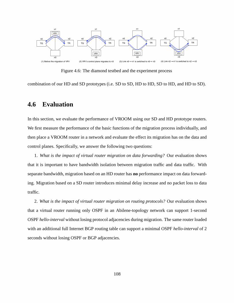
TG TR
n0
n1
n2
n3
VR1
TG TR
n0
n1
n2
n3
VR1
TG TR
n0
n1
n2
n3
VR1
TG TR
n0
n1
n2
n3
VR1
(1) Before the migration of VR1 (2) VR1's control plane migrates to n3 (3) Link n0 n1 is switched to n0 n3 (4) Link n2 n1 is switched to n2 n3
Figure 4.6: The diamond testbed and the experiment process
combination of our HD and SD prototypes (i.e. SD to SD, HD to HD, SD to HD, and HD to SD).
4.6 Evaluation
In this section, we evaluate the performance of VROOM using our SD and HD prototype routers.
We first measure the performance of the basic functions of themigration process individually, and
then place a VROOM router in a network and evaluate the effectits migration has on the data and
control planes. Specifically, we answer the following two questions:
1. What is the impact of virtual router migration on data forwarding? Our evaluation shows
that it is important to have bandwidth isolation between migration traffic and data traffic. With
separate bandwidth, migration based on an HD router hasno performance impact on data forward-
ing. Migration based on a SD router introduces minimal delayincrease and no packet loss to data
traffic.
2. What is the impact of virtual router migration on routing protocols?Our evaluation shows
that a virtual router running only OSPF in an Abilene-topology network can support 1-second
OSPFhello-intervalwithout losing protocol adjacencies during migration. Thesame router loaded
with an additional full Internet BGP routing table can support a minimal OSPFhello-intervalof 2
seconds without losing OSPF or BGP adjacencies.
108
n0
n1
n3 n4
n5
n6
VR1
data traffic migration traffic
Figure 4.7: The dumbbell testbed for studying bandwidth contention between migration traffic anddata traffic. Virtual router VR1 migrates from n0 to n5. Round-trip traffic is sent between n1 andn6.
4.6.1 Methodology
Our evaluation involved experiments conducted in the Emulab tesbed [32]. We primarily used
PC3000 machines as the physical nodes in our experiments. The PC3000 is an Intel Xeon 3.0
GHz 64-bit platform with 2GB RAM and five Gigabit Ethernet NICs. For the HD prototype, each
physical node was additionally equipped with a NetFPGA card. All nodes in our experiments were
running an OpenVZ patched Linux kernel 2.6.18-ovz028stab049.1. For a few experiments we also
used the lower performance PC850 physical nodes, built on anIntel Pentium III 850MHz platform
with 512MB RAM and five 100Mbps Ethernet NICs.
We used three different testbed topologies in our experiments:
The diamond testbed:We use the 4-node diamond-topology testbed (Figure 4.6) to evaluate the
performance of individual migration functions and the impact of migration on the data plane. The
testbed has two different configurations, which have the same type of machines as physical node
n0 and n2, but differ in the hardware on node n1 and n3. In theSDconfiguration, n1 and n3 are
regular PCs on which we install our SD prototype routers. In theHD configuration, n1 and n3 are
PCs each with a NetFPGA card, on which we install our HD prototype routers. In the experiments,
virtual router VR1 is migrated from n1 to n3 through link n1→n3.
The dumbbell testbed: We use a 6-node dumbbell-shaped testbed to study the bandwidth con-
109

Seattle
Sunnyvale
Los Angeles
Kansas CityDenver
Houston
Chicago-1
Indianapolis
Chicago-2
New York
Washington D.C.
Atlanta
VR1
VR2 VR3
VR4
VR5 VR6
VR7
VR8
VR9
VR10
VR11
Figure 4.8: The Abilene testbed
Table 4.1: The memory dump file size of virtual router with different numbers of OSPF routes
Routes 0 10k 100k 200k 300k 400k 500k
Size (MB) 3.2 24.2 46.4 58.4 71.1 97.3 124.1
tention between migration traffic and data traffic. In the testbed, round-trip UDP data traffic is sent
between a pair of nodes while a virtual router is being migrated between another pair of nodes. The
migration traffic and data traffic are forced to share the samephysical link, as shown in Figure 4.7.
The Abilene testbed:We use a 12-node testbed (Figure 4.8) to evaluate the impact of migration
on the control plane. It has a topology similar to the 11-nodeAbilene network backbone [2]. The
only difference is that we add an additional physical node (Chicago-2), to which the virtual router
on Chicago-1 (V5) is migrated. Figure 4.8 shows the initial topology of the virtual network, where
11 virtual routers (V1 to V11) run on the 11 physical nodes (except Chicago-2) respectively.
4.6.2 Performance of Migration Steps
In this subsection, we evaluate the performance of the two main migration functions of the prototypes—
memory copy and FIB repopulation.
Memory copy: To evaluate memory copy time relative to the memory usage of the virtual router,
we load theospfd in VR1 with different numbers of routes. Table 4.1 lists the respective memory
dump file sizes of VR1. Figure 4.9 shows the total time it takesto complete the memory-copy step,
110
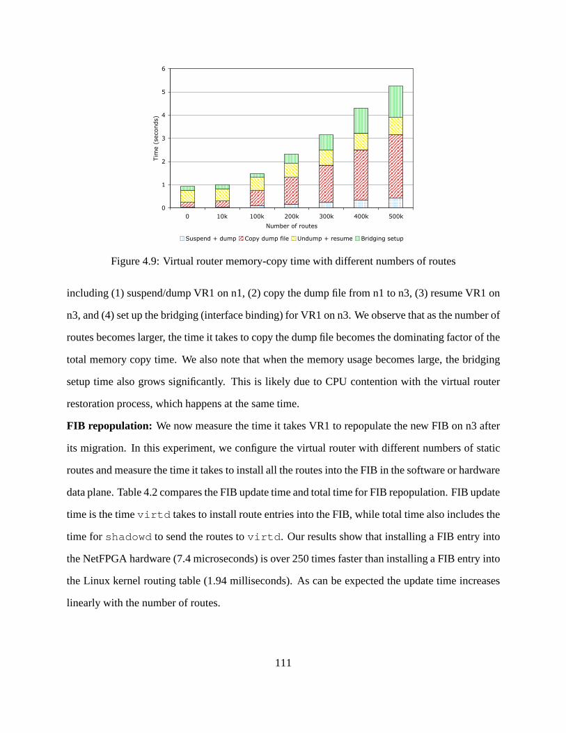
0
1
2
3
4
5
6
0 10k 100k 200k 300k 400k 500k
Number of routes
Time (seconds)
Suspend + dump Copy dump file Undump + resume Bridging setup
Figure 4.9: Virtual router memory-copy time with differentnumbers of routes
including (1) suspend/dump VR1 on n1, (2) copy the dump file from n1 to n3, (3) resume VR1 on
n3, and (4) set up the bridging (interface binding) for VR1 onn3. We observe that as the number of
routes becomes larger, the time it takes to copy the dump file becomes the dominating factor of the
total memory copy time. We also note that when the memory usage becomes large, the bridging
setup time also grows significantly. This is likely due to CPUcontention with the virtual router
restoration process, which happens at the same time.
FIB repopulation: We now measure the time it takes VR1 to repopulate the new FIB on n3 after
its migration. In this experiment, we configure the virtual router with different numbers of static
routes and measure the time it takes to install all the routesinto the FIB in the software or hardware
data plane. Table 4.2 compares the FIB update time and total time for FIB repopulation. FIB update
time is the timevirtd takes to install route entries into the FIB, while total timealso includes the
time forshadowd to send the routes tovirtd. Our results show that installing a FIB entry into
the NetFPGA hardware (7.4 microseconds) is over 250 times faster than installing a FIB entry into
the Linux kernel routing table (1.94 milliseconds). As can be expected the update time increases
linearly with the number of routes.
111
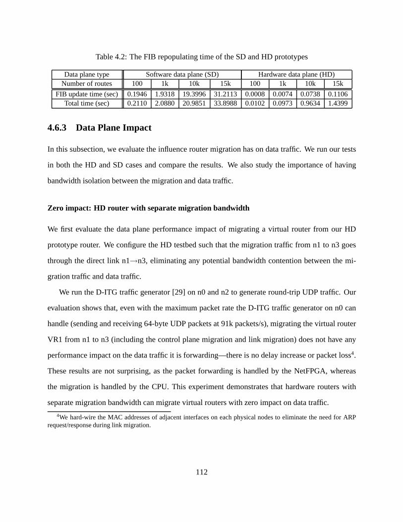
Table 4.2: The FIB repopulating time of the SD and HD prototypes
Data plane type Software data plane (SD) Hardware data plane (HD)Number of routes 100 1k 10k 15k 100 1k 10k 15k
FIB update time (sec) 0.1946 1.9318 19.3996 31.2113 0.0008 0.0074 0.0738 0.1106Total time (sec) 0.2110 2.0880 20.9851 33.8988 0.0102 0.0973 0.9634 1.4399
4.6.3 Data Plane Impact
In this subsection, we evaluate the influence router migration has on data traffic. We run our tests
in both the HD and SD cases and compare the results. We also study the importance of having
bandwidth isolation between the migration and data traffic.
Zero impact: HD router with separate migration bandwidth
We first evaluate the data plane performance impact of migrating a virtual router from our HD
prototype router. We configure the HD testbed such that the migration traffic from n1 to n3 goes
through the direct link n1→n3, eliminating any potential bandwidth contention between the mi-
gration traffic and data traffic.
We run the D-ITG traffic generator [29] on n0 and n2 to generateround-trip UDP traffic. Our
evaluation shows that, even with the maximum packet rate theD-ITG traffic generator on n0 can
handle (sending and receiving 64-byte UDP packets at 91k packets/s), migrating the virtual router
VR1 from n1 to n3 (including the control plane migration and link migration) does not have any
performance impact on the data traffic it is forwarding—there is no delay increase or packet loss4.
These results are not surprising, as the packet forwarding is handled by the NetFPGA, whereas
the migration is handled by the CPU. This experiment demonstrates that hardware routers with
separate migration bandwidth can migrate virtual routers with zero impact on data traffic.
4We hard-wire the MAC addresses of adjacent interfaces on each physical nodes to eliminate the need for ARPrequest/response during link migration.
112

Minimal impact: SD router with separate migration bandwidt h
In the SD router case, CPU is the resource that could potentially become scarce during migration,
because the control plane and data plane of a virtual router share the same CPU. We now study
the case in which migration and packet forwarding together saturate the CPU of the physical node.
As with the HD experiments above, we use link n1→n3 for the migration traffic to eliminate any
bandwidth contention.
In order to create a CPU bottleneck on n1, we use PC3000 machines on n0 and n2 and use
lower performance PC850 machines on n1 and n3. We migrate VR1from n1 to n3 while sending
round-trip UDP data traffic between nodes n0 and n2. We vary the packet rate of the data traffic
from 1k to 30k packets/s and observe the performance impact the data traffic experiences due to the
migration. (30k packets/s is the maximum bi-directional packet rate a PC850 machine can handle
without dropping packets.)
Somewhat surprisingly, the delay increase caused by the migration is only noticeable when
the packet rate is relatively low. When the UDP packet rate isat 5k packets/s, the control plane
migration causes sporadic round-trip delay increases up to3.7%. However, when the packet rate
is higher (e.g., 25k packets/s), the change in delay during the migration is negligible (< 0.4%).
This is because the packet forwarding is handled by kernel threads, whereas the OpenVZ mi-
gration is handled by user-level processes (e.g.,ssh, rsync, etc.). Although kernel threads have
higher priority than user-level processes in scheduling, Linux has a mechanism that prevents user-
level processes from starving when the packet rate is high. This explains the delay increase when
migration is in progress. However, the higher the packet rate is, the more frequently the user-level
migration processes are interrupted, and more frequently the packet handler is called. Therefore,
the higher the packet rate gets, the less additional delay the migration processes add to the packet
forwarding. This explains why when the packet rate is 25k packets/s, the delay increase caused
by migration becomes negligible. This also explains why migration does not cause any packet
drops in the experiments. Finally, our experiments indicate that the link migration does not affect
113

Table 4.3: Packet loss rate of the data traffic, with and without migration traffic
Data traffic rate (Mbps) 500 600 700 800 900
Baseline (%) 0 0 0 0 0.09w/ migration traffic (%) 0 0 0.04 0.14 0.29
forwarding delay.
Reserved migration bandwidth is important
0
50
100
150
200
250
300
350
400
450
500 600 700 800 900
Del
ay in
crea
se (
%)
Data traffic rate (Mbps)
Figure 4.10: Delay increase of the data traffic, due to bandwidth contention with migration traffic
In 4.6.3 and 4.6.3, migration traffic is given its own link (i.e., has separate bandwidth). Here
we study the importance of this requirement and the performance implications for data traffic if it
is not met.
We use the dumbbell testbed in this experiment, where migration traffic and data traffic share
the same bottleneck link. We load theospfd of a virtual router with 250k routes. We start the
data traffic rate from 500 Mbps, and gradually increase it to 900 Mbps. Because OpenVZ uses
TCP (scp) for memory copy, the migration traffic only receives the left-over bandwidth of the
UDP data traffic. As the available bandwidth decreases to below 300 Mbps, the migration time
increases, which translates into a longer control-plane downtime for the virtual router.
Figure 4.10 compares the delay increase of the data traffic atdifferent rates. Both the aver-
114
age delay and the delay jitter increase dramatically as the bandwidth contention becomes severe.
Table 4.3 compares the packet loss rates of the data traffic atdifferent rates, with and without mi-
gration traffic. Not surprisingly, bandwidth contention (i.e., data traffic rate≥ 700 Mbps) causes
data packet loss. The above results indicate that in order tominimize the control-plane downtime of
the virtual router, and to eliminate the performance impactto data traffic, operators should provide
separate bandwidth for the migration traffic.
4.6.4 Control Plane Impact
In this subsection, we investigate the control plane dynamics introduced by router migration, es-
pecially how migration affects the protocol adjacencies. We assume a backbone network running
MPLS, in which its edge routers run OSPF and BGP, while its core routers run only OSPF. Our
results show that, with default timers, protocol adjacencies of both OSPF and BGP are kept intact,
and at most one OSPF LSA retransmission is needed in the worstcase.
Core Router Migration
We configure virtual routers VR1, VR6, VR8 and VR10 on the Abilene testbed (Figure 4.8) as edge
routers, and the remaining virtual routers as core routers.By migrating VR5 from physical node
Chicago-1 to Chicago-2, we observe the impact of migrating acore router on OSPF dynamics.
No events during migration: We first look at the case in which there are no network events during
the migration. Our experiment results show that the control-plane downtime of VR5 is between
0.924 and 1.008 seconds, with an average of 0.972 seconds over 10 runs.
We start with the default OSPF timers of Cisco routers:hello-intervalof 10 seconds anddead-
interval of 40 seconds. We then reduce thehello-interval to 5, 2, and 1 second in subsequent
runs, while keeping thedead-intervalequal to four times thehello-interval. We find that the OSPF
adjacencies between the migrating VR5 and its neighbors (VR4 and VR6) stay up in all cases.
Even in the most restrictive 1-secondhello-intervalcase, at most one OSPF hello message is lost
115
and VR5 comes back up on Chicago-2 before its neighbors’ deadtimers expire.
Events happen during migration: We then investigate the case in which there are events during
the migration and the migrating router VR5 misses the LSAs triggered by the events. We trigger
new LSAs by flapping the link between VR2 and VR3. We observe that VR5 misses an LSA when
the LSA is generated during VR5’s 1-second downtime. In sucha case, VR5 gets a retransmission
of the missing LSA 5 seconds later, which is the default LSAretransmit-interval.
We then reduce the LSAretransmit-intervalfrom 5 seconds to 1 second, in order to reduce
the time that VR5 may have a stale view of the network. This change brings down the maximum
interval between the occurrence of a link flap and VR5’s reception of the resulting LSA to 2 seconds
(i.e., the 1 second control plane downtime plus the 1 second LSA retransmit-interval).
Edge Router Migration
Here we configure VR5 as the fifth edge router in the network that runs BGP in addition to OSPF.
VR5 receives a full Internet BGP routing table with 255k routes (obtained from RouteViewson
Dec 12, 2007) from an eBGP peer that is not included in Figure 4.8, and it forms an iBGP full
mesh with the other four edge routers.
With the addition of a full BGP table, the memory dump file sizegrows from 3.2 MB to 76.0
MB. As a result, it takes longer to suspend/dump the virtual router, copy over its dump file, and
resume it. The average downtime of the control plane during migration increases to between 3.484
and 3.594 seconds, with an average of 3.560 seconds over 10 runs. We observe that all of VR5’s
BGP sessions stay intact during its migration. The minimal integerhello-intervalVR5 can support
without breaking its OSPF adjacencies during migration is 2seconds (withdead-intervalset to 8
seconds). In practice, ISPs are unlikely to set the timers much lower than the default values, in
order to shield themselves from faulty links or equipment.
116

4.7 Migration Scheduling
Besides the question of migration mechanisms (“how to migrate”), another important question is
the migration scheduling (“where to migrate”). Here we briefly discuss the constraints that need to
be considered when scheduling migration and several optimization formulations that can be used
in VROOM migration scheduling.
When deciding where to migrate a virtual router, several physical constraints need to be taken
into consideration. First of all, an “eligible” destination physical router for migration must use
a software platformcompatible with the original physical router, and have similar (or greater)
capabilities(such as the number of access control lists supported). In addition, the destination
physical router must have sufficient resources available, includingprocessing power(whether the
physical router is already hosting the maximum number of virtual routers it can support) andlink
capacity(whether the links connected to the physical router have enough unused bandwidth to
handle the migrating virtual router’s traffic load). Furthermore, theredundancyrequirement of the
virtual router also needs to be considered—today a router isusually connected to two different
routers (one as primary and the other as backup) for redundancy. If the primary and backup are
migrated to the same node, physical redundancy will be lost.
Fortunately, ISPs typically leave enough “head room” in link capacities to absorb increased
traffic volume. Additionally, most ISPs use routers from oneor two vendors, with a small number
of models, which leaves a large number of eligible physical routers to be chosen for the migration.
Given a physical router that requires maintenance, the question of where to migrate the virtual
routers it currently hosts can be formulated as an optimization problem, subject to all the above
constraints. Depending on the preference of the operator, different objectives can be used to pick
the best destination router, such as minimizing the overallCPU load of the physical router, min-
imizing the maximum load of physical links in the network, minimizing the stretch (i.e., latency
increase) of virtual links introduced by the migration, or maximizing the reliability of the network
117

(e.g., the ability to survive the failure of any physical node or link). However, finding optimal
solutions to these problems may be computationally intractable. Fortunately, simple local-search
algorithms should perform reasonably well, since the number of physical routers to consider is
limited (e.g., to hundreds or small thousands, even for large ISPs) and finding a “good” solution
(rather than an optimal one) is acceptable in practice. In the case of power savings, we take the
power prices in different geographic locations into account and try to minimize power consumption
with a certain migration granularity (e.g., once every hour, according to the hourly traffic matrices).
4.8 Related Work
VROOM’s motivation is similar, in part, to that of the RouterFarm work [4], namely, to reduce the
impact of planned maintenance by migrating router functionality from one place in the network
to another. However, RouterFarm essentially performs a “cold restart”, compared to VROOM’s
live (“hot”) migration. Specifically, in RouterFarm routermigration is realized by re-instantiating
a router instance at the new location, which not only requires router reconfiguration, but also in-
troduces inevitable downtime in both the control and data planes. In VROOM, on the other hand,
we performlive router migration without reconfiguration or discernible disruption. In our earlier
prototype of VROOM [106], router migration was realized by directly using the standard virtual
machine migration capability provided by Xen [9], which lacked the control and data plane sepa-
ration presented in this chapter. As a result, it involved data-plane downtime during the migration
process.
Recent advances in virtual machine technologies and their live migration capabilities [27, 73]
have been leveraged in server-management tools, primarilyin data centers. For example, Sand-
piper [109] automatically migrates virtual servers acrossa pool of physical servers to alleviate
hotspots. Usher [69] allows administrators to express a variety of policies for managing clusters of
virtual servers. Remus [28] uses asynchronous virtual machine replication to provide high avail-
118

ability to server in the face of hardware failures. In contrast, VROOM focuses on leveraging live
migration techniques to simplify management in the networking domain.
Network virtualization has been proposed in various contexts. Early work includes the “switch-
lets” concept, in which ATM switches are partitioned to enable dynamic creation of virtual net-
works [95]. More recently, the CABO architecture proposes to use virtualization as a means to
enable multiple service providers to share the same physical infrastructure [34]. Outside the re-
search community, router virtualization has already become available in several forms in com-
mercial routers [25, 57]. In VROOM, we take an additional step not only to virtualize the router
functionality, but also to decouple the virtualized routerfrom its physical host and enable it to
migrate.
VROOM also relates to recent work on minimizing transient routing disruptions during planned
maintenance. A measurement study of a large ISP showed that more than half of routing changes
were planned in advance [55]. Network operators can limit the disruption by reconfiguring the
routing protocols to direct traffic away from the equipment undergoing maintenance [93, 41]. In
addition, extensions to the routing protocols can allow a router to continue forwarding packets in
the data plane while reinstalling or rebooting the control-plane software [90, 21]. However, these
techniques require changes to the logical configuration or the routing software, respectively. In
contrast, VROOM hides the effects of physical topology changes in the first place, obviating the
need for point solutions that increase system complexity while enabling new network-management
capabilities, as discussed in the next section.
4.9 Summary
VROOM is a new network-management primitive that supports live migration of virtual routers
from one physical router to another. To minimize disruptions, VROOM allows the migrated con-
trol plane to clone the data-plane state at the new location while continuing to update the state at
119

the old location. VROOM temporarily forwards packets usingboth data planes to support asyn-
chronous migration of the links. These designs are readily applicable to commercial router plat-
forms. Experiments with our prototype system demonstrate that VROOM does not disrupt the data
plane and only briefly freezes the control plane. In the unlikely scenario that a control-plane event
occurs during the freeze, the effects are largely hidden by existing mechanisms for retransmitting
routing-protocol messages. VROOM provides a new, disruption-free mechanism to handle a broad
range of network management tasks, such as planned maintenance, service deployment and power
savings.
120
Chapter 5
Conclusion
Today’s ISPs face a number of major challenges in better managing routing in their networks to
provide competitive services, including (1) maintaining the stability of theglobal Internet while
meeting the increasing demands from its customers for diverse routes, (2) supporting intuitive and
more flexible routing policy configuration in bilateral contractual relationships with itsneighbors,
and (3) making network maintenance and other network management operations in theirownnet-
works easier and less disruptive to routing protocols and data traffic. This dissertation takes a
principledapproach to addressing these challenges with a set of new abstractions, as well as the-
oretical results and systems guided by these abstractions.In this chapter, we first summarize the
contributions of this dissertation in Section 5.1. We then discuss the synergy between Morpheus
and VROOM and the additional benefits an ISP can get by deploying the two systems together in
Section 5.2. We briefly propose some future research directions based on the work done in this
dissertation and conclude in Section 5.3.
121

5.1 Summary of Contributions
This dissertation identified three major routing management challenges faced by ISPs today and
presented corresponding theoretical and/or system solutions.
First, we observed that there are many useful routing policies that cannot be realized (config-
ured) today, and argued that it is mainly caused by the “one-route-fits-all” BGP route-selection
model. Acknowledging the fact that different customers of an ISP are increasingly likely to prefer
routes with different properties, we proposed the abstraction of a “neighbor-specific route selection
problem” and a corresponding “Neighbor-Specific BGP” (NS-BGP) model that enables an ISP to
offer customized route-selection services to different neighbors. We also proved a surprisingly
positive result that, comparing to conventional BGP, a lessrestrictive sufficient condition can guar-
antee the stability of the more flexible NS-BGP. Our stability conditions allow an AS to selectany
exportable routes for its neighbors without compromising global stability. This result provides a
new understanding of the fundamental trade-off between local policy flexibility and global routing
stability. We also show that NS-BGP remains stable even in partial deployment and in the presence
of network failures, as long as the stability conditions arefollowed. As as result, any individual
ISP can deploy NS-BGP independently by modifying how routesare selected and disseminated
within its network, without modifying the BGP message format or requiring collaboration from
neighboring domains.
Second, we argued that the notorious difficulty of routing policy configuration is mainly due to
two reasons: the mismatch between how the policies arespecifiedand how they areimplemented;
as well as the counterintuitive and restrictive BGP configuration interface. We presented the design,
implementation and evaluation of Morpheus, a routing control platform that supports customized
route selection (NS-BGP) and simplifies policy configuration through an expressive yet intuitive
configuration interface. Morpheus enables network operators to easily define new policy objec-
tives, make flexible trade-offs between objectives, and therefore realize a much broader range of
122
routing policies than conventional BGP.
Finally, we argued that the traffic disruption caused by routine planned maintenance and other
network management tasks is due to theunnecessaryrouting configuration changes used as a tool
to help physical network changes. Hence, we propose the abstraction of the separation between
“physical” and “logical” configurations of routers, which leads us to the design and prototype
implementation of “virtual router migration” (VROOM), a new, generic technique to simplify and
enable a broad range of network management tasks, from planned maintenance to reducing power
consumption.
Collectively, the contributions of the dissertation provide simple system solutions for an ISP
to autonomously manage its routing more flexibly and effectively without affecting global routing
stability.
5.2 The Synergy of Deploying Morpheus and VROOM Together
Depending on its need, an ISP can choose to deploy only Morpheus or VROOM. However, the two
systems together bring additional synergies to each other if deployed together.
On the one hand, Morpheus makes the virtual router migrationprocess of VROOM faster. This
is because with Morpheus, individual routers no longer holdBGP states in their control plane (as
these states are maintained in the Morpheus servers instead); therefore, only IGP states need to
be copied during migration, which has far smaller memory footprint compared to BGP states and
can be transferred very quickly. On the other hand, with VROOM, an ISP no longer needs to
make configuration changes to Morpheus (and other routers) to assist physical network changes.
VROOM can also help reduce the churn of routing updates in a Morpheus-enabled ISP as many
network management tasks such as planned maintenance no longer cause protocol reconvergence.
When deployed together, Morpheus and VROOM simplify the management of an ISP by sep-
arating different concerns — Morpheus enables network operators to focus on realizing desir-
123

able routing policies without thinking about underlying physical changes to the network, whereas
VROOM allows network operators to carry out physical changes to the network without worrying
about disrupting routing protocol adjacencies and data traffic. As a result, each individual task
becomes less complicated, less error-prone and more predictable.
5.3 Open Issues and Future Work
The work presented in this dissertation raised a number of questions that deserve further investiga-
tion in the future.
5.3.1 Using Morpheus and VROOM to Handle Traffic Engineering
Most policy objectives can be expressed in terms of ratings (preferences) for individual routes.
A notable exception is traffic engineering (TE), since the total traffic on each link in the network
depends on the mixture of traffic to many different destinations. Today, network operators perform
TE by tuning the IGP link weights or configuring MPLS tunnels (in the case of MPLS TE) to
move traffic away from congested links. With Morpheus, the network operators can also configure
the egress-point rankings to manipulate the flow of traffic. In addition, although some customers
will subscribe to customized routes, the remaining customers will still use whatever paths the ISP
selects as the “default”. Controlling the route-selectionprocess for the default customers gives
the ISP substantial leeway to perform TE. As such, providinggreater flexibility in path selection
serves as an enabler for effective traffic engineering. We believe that exploring these issues in
greater depth is a promising avenue for future research.
VROOM provides another interesting alternative to the current TE practice—using virtual
router migration as a TE primitive. When a physical link connected to a physical router is over-
loaded, a portion of the traffic can be offloaded by migrating one or more virtual routers running
on the physical router (and the corresponding virtual links) to a different node. This mechanism
124

could be more appealing than other mechanisms that involve protocol reconfiguration and recon-
vergence, especially for alleviating “flash crowd” type of traffic surge that lasts for a short period
of time (so that traffic taking a slight detour from the shortest paths computed by IGP is less of a
concern.)
5.3.2 The Evolving Functions of Routers
Our research on VROOM raises several broader questions about the design of future routers and
the relationship with the underlying transport network. Recent innovations in transport networks
support rapid set-up and tear-down of links, enabling the network topology to change underneath
the IP routers. Dynamic topologies coupled with VROOM’s migration of the control plane and
cloning of the data plane make the router an increasingly ephemeral concept, not tied to a particular
location or piece of hardware. Future work on router hypervisors could take this idea one step
further. Just as today’s commercial routers have a clear separation between the control and data
planes, future routers could decouple the control-plane software (executables) and the control-
plane states (e.g., RIBs and state in the state machine for each routing-protocol adjacency, etc.).
Such a “control-plane hypervisor” would make it easier to upgrade router software while retaining
the states, and for virtual routers to migrate between different kinds of physical router platforms
(e.g., those from different vendors and / or running different code bases).
5.3.3 Dynamics of NS-BGP
In this dissertation, we focused primarily on the stabilityconditions of NS-BGP. Another interest-
ing aspect of this new route-selection model is its dynamics, especially the speed of its conver-
gence (compared to conventional BGP). We observe that, at the very minimum, existing proposals
(e.g., [19]) that aim at addressing the path exploration problem—the main cause of the slow BGP
convergence—can also be applied to NS-BGP. Other issues that have been studied for conventional
125
BGP, such as complexity results and root-cause analysis, could also be revisited in the context of
NS-BGP.
5.4 Concluding Remarks
This dissertation has (1) presented a new, neighbor-specific BGP (NS-BGP) route-selection model
that allows an ISP to provide customized routes to its customers, and proved the conditions that
guarantee global stability of the Internet when ISPs switchto the NS-BGP model; (3) designed
and implemented a routing control platform that supports NS-BGP and much broader range of
routing policies (compared to conventional BGP) via a new, intuitive configuration interface; (4)
developed a new technique (virtual router migration) that enables many network management tasks
to be conducted without disrupting routing protocol adjacencies or data traffic.
At a high-level, the work presented in this dissertation is motivated by revisiting and challeng-
ing previous unquestionable assumptions (such as “one-route-fits-all works well enough”, “com-
puting BGP routes in a centralized fashion does not scale”, “a router is a piece of monolithic
equipment”), and is enabled by leveraging theory from otherfields (such as the Analytic Hierarchy
Process from decision theory) and the advancement of related technologies (such as the steady in-
crease of computational power under Moore’s Law, server virtualization, programmable transport
network). We believe that, as enabling technologies keep emerging and/or evolving, revisiting as-
sumptions that previous design decisions were based upon and leveraging emerging technologies
will remain an effective approach to addressing network management challenges.
126

Bibliography
[1] http://www.networksorcery.com/enp/protocol/bgp.htm.
[2] The Internet2 Network.http://www.internet2.edu/.
[3] T. Afferton, R. Doverspike, C. Kalmanek, and K. K. Ramakrishnan. Packet-aware transport for metro
networks.IEEE Communication Magazine, March 2004.
[4] M. Agrawal, S. Bailey, A. Greenberg, J. Pastor, P. Sebos,S. Seshan, J. van der Merwe, and J. Yates.
RouterFarm: Towards a dynamic, manageable network edge. InProc. ACM SIGCOMM Workshop
on Internet Network Management (INM), September 2006.
[5] C. Alaettinoglu, C. Villamizar, E. Gerich, D. Kessens, D. Meyer, T. Bates, D. Karrenberg, and
M. Terpstra. Routing policy specification language (RPSL).RFC 2622, June 1999.
[6] H. Alzoubi, S. Lee, M. Rabinovich, O. Spatscheck, and J. van der Merwe. Anycast CDNs revisited.
In Proc. International World Wide Web Conference, 2008.
[7] I. Avramopoulos, J. Rexford, and R. Schapire. From optimization to regret minimization and back
again. InProc. Third Workshop on Tackling Computer System Problems with Machine Learning
Techniques (SysML08), December 2008.
[8] D. O. Awduche, A. Chiu, A. Elwalid, I. Widjaja, and X. Xiao. Overview and principles of Internet
traffic engineering. RFC 3272, May 2002.
[9] P. Barham, B. Dragovic, K. Fraser, S. Hand, T. Harris, A. Ho, R. Neugebar, I. Pratt, and A. Warfield.
Xen and the art of virtualization. InProc. Symposium on Operating Systems Principles (SOSP),
October 2003.
[10] A. Basu, C.-H. L. Ong, A. Rasala, F. B. Shepherd, and G. Wilfong. Route oscillations in I-BGP with
127

route reflection. InProc. ACM SIGCOMM, August 2002.
[11] V. Belton. Multiple Criteria Decision Analysis. Springer, 2003.
[12] H. Boehm, A. Feldmann, O. Maennel, C. Reiser, and R. Volk. Network-wide inter-domain routing
policies: Design and realization.Draft, April 2005.
[13] O. Bonaventure, C. Filsfils, and P. Francois. Achievingsub-50 milliseconds recovery upon BGP
peering link failures.IEEE/ACM Trans. Networking, October 2007.
[14] S. Bryant and P. Pate. Pseudo wire emulation edge-to-edge (PWE3) architecture. RFC 3985, March
2005.
[15] M. Caesar, D. Caldwell, N. Feamster, J. Rexford, A. Shaikh, and J. van der Merwe. Design and im-
plementation of a Routing Control Platform. InProc. Networked Systems Design and Implementation
(NSDI), May 2005.
[16] M. Caesar and J. Rexford. BGP policies in ISP networks.IEEE Network Magazine, October 2005.
[17] J. Chabarek, J. Sommers, P. Barford, C. Estan, D. Tsiang, and S. Wright. Power awareness in network
design and routing. InProc. IEEE INFOCOM, 2008.
[18] V. Chandola, A. Banerjee, and V. Kumar. Anomaly detection: A survey.To appear in ACM Comput-
ing Surveys, September 2009.
[19] J. Chandrashekar, Z. Duan, J. Krasky, and Z.-L. Zhang. Limiting path exploration in BGP. InProc.
IEEE INFOCOM, March 2005.
[20] C.-K. Chau. Policy-based routing with non-strict preferences. InProc. ACM SIGCOMM, 2006.
[21] E. Chen, R. Fernando, J. Scudder, and Y. Rekhter. Graceful Restart Mechanism for BGP. RFC 4724,
January 2007.
[22] Ciena CoreDirector Multiservice Switch.www.ciena.com.
[23] Cisco Optimized Edge Routing.http://www.cisco.com/en/US/products/ps6628/
products_ios_protocol_option_home.html.
[24] MPLS VPN Carrier Supporting Carrier.http://www.cisco.com/en/US/docs/ios/12_
0st/12_0st14/feature/guide/csc.html.
[25] Cisco Logical Routers.http://www.cisco.com/en/US/docs/ios_xr_sw/iosxr_r3.
2/interfaces/command/reference/hr32lr.html.
128

[26] MPLS Fundamentals: Forwarding Labeled Packets.http://www.ciscopress.com/
articles/article.asp?p=680824&seqNum=2.
[27] C. Clark, K. Fraser, S. Hand, J. G. Hansen, E. Jul, C. Limpach, I. Pratt, and A. Warfield. Live
migration of virtual machines. InProc. Networked Systems Design and Implementation (NSDI), May
2005.
[28] B. Cully, G. Lefebvre, D. Meyer, M. Feeley, N. Hutchinson, and A. Warfield. Remus: High avail-
ability via asynchronous virtual machine replication. InProc. Networked Systems Design and Imple-
mentation (NSDI), April 2008.
[29] D-ITG. http://www.grid.unina.it/software/ITG/.
[30] N. Duffield, K. Gopalan, M. R. Hines, A. Shaikh, and J. vander Merwe. Measurement informed
route selection. InProc. Passive and Active Measurement Conference (ExtendedAbstract), 2007.
[31] A. Elwalid, C. Jin, S. Low, and I. Widjaja. MATE: MPLS adaptive traffic engineering. InProc. IEEE
INFOCOM, 2001.
[32] Emulab.http://www.emulab.net.
[33] N. Feamster, H. Balakrishnan, J. Rexford, A. Shaikh, and J. van der Merwe. The case for sepa-
rating routing from routers. InProc. ACM SIGCOMM Workshop on Future Direction in Network
Architecture, August 2004.
[34] N. Feamster, L. Gao, and J. Rexford. How to lease the Internet in your spare time.ACM Computer
Communication Review, pages 61–64, January 2007.
[35] N. Feamster, R. Johari, and H. Balakrishnan. Implications of autonomy for the expressiveness of
policy routing. InProc. ACM SIGCOMM, August 2005.
[36] J. Feigenbaum, C. Papadimitriou, R. Sami, and S. Shenker. A BGP-based mechanism for lowest-cost
routing. Distributed Computing, 18:61–72, 2005.
[37] J. Feigenbaum, R. Sami, and S. Shenker. Mechanism design for policy routing.Distributed Comput-
ing, 18(4):293–305, 2006.
[38] A. Feldmann and J. Rexford. IP network configuration forintradomain traffic engineering.IEEE
Network Magazine, pages 46–57, September/October 2001.
[39] S. Fischer, N. Kammenhuber, and A. Feldmann. REPLEX — dynamic traffic engineering based on
129
wardrop routing policies. InProc. CoNext, December 2006.
[40] B. Fortz and M. Thorup. Internet traffic engineering by optimizing OSPF weights. InProc. IEEE
INFOCOM, March 2000.
[41] P. Francois, M. Shand, and O. Bonaventure. Disruption-free topology reconfiguration in OSPF net-
works. InProc. IEEE INFOCOM, May 2007.
[42] L. Gao, T. G. Griffin, and J. Rexford. Inherently safe backup routing with BGP. InProc. IEEE
INFOCOM, pages 547–556, April 2001.
[43] L. Gao and J. Rexford. Stable Internet routing without global coordination. IEEE/ACM Trans.
Networking, December 2001.
[44] S. Goldberg, S. Halevi, A. Jaggard, V. Ramachandran, and R. Wright. Rationality and traffic attrac-
tion: Incentives for honestly announcing paths in BGP. InProc. ACM SIGCOMM, August 2008.
[45] T. Griffin and G. Huston. BGP wedgies. RFC 4264, November2005.
[46] T. Griffin, A. Jaggard, and V. Ramachandran. Design principles of policy languages for path vector
protocols. InProc. ACM SIGCOMM, pages 61–72, Karlsruhe, Germany, August 2003.
[47] T. Griffin, F. B. Shepherd, and G. Wilfong. Policy disputes in path-vector protocols. InProc. Inter-
national Conference on Network Protocols (ICNP), November 1999.
[48] T. Griffin, F. B. Shepherd, and G. Wilfong. The stable paths problem and interdomain routing.
IEEE/ACM Trans. Networking, 10(1):232–243, 2002.
[49] T. Griffin and G. Wilfong. An analysis of BGP convergenceproperties. InProc. ACM SIGCOMM,
September 1999.
[50] T. Griffin and G. Wilfong. Analysis of the MED oscillation problem in BGP. InProc. International
Conference on Network Protocols (ICNP), Paris, France, November 2002.
[51] T. Griffin and G. Wilfong. On the correctness of IBGP configuration.SIGCOMM Comput. Commun.
Rev., 32(4):17–29, 2002.
[52] M. Gupta and S. Singh. Greening of the Internet. InProc. ACM SIGCOMM, August 2003.
[53] M. Handley, E. Kohler, A. Ghosh, O. Hodson, and P. Radoslavov. Designing extensible IP router
software. InProc. Networked Systems Design and Implementation (NSDI), May 2005.
[54] J. He, M. Suchara, M. Bresler, J. Rexford, and M. Chiang.Rethinking Internet traffic management:
130
From multiple decompositions to a practical protocol. InProc. CoNext, December 2007.
[55] G. Iannaccone, C.-N. Chuah, S. Bhattacharyya, and C. Diot. Feasibility of IP restoration in a tier-1
backbone.IEEE Network Magazine, Mar 2004.
[56] IETF. Advertisement of Multiple Paths in BGP, July 2008.http://tools.ietf.org/html/
draft-walton-bgp-add-paths-06. Internet Draft. Expires January 2009.
[57] Juniper Logical Routers. http://www.juniper.net/techpubs/software/junos/
junos85/feature-guide-85/id-11139212.html.
[58] S. Kandula, D. Katabi, B. Davie, and A. Charny. Walking the tightrope: Responsive yet stable traffic
engineering. InProc. ACM SIGCOMM, August 2005.
[59] J. Karlin, S. Forrest, and J. Rexford. Autonomous security for autonomous systems.Computer
Networks, October 2008.
[60] Z. Kerravala. Configuration management delivers business resiliency. The Yankee Group, November
2002.
[61] R. R. Kompella, S. Singh, and G. Varghese. On scalable attack detection in the network. InProc.
Internet Measurement Conference (IMC), October 2004.
[62] C. Labovitz, A. Ahuja, A. Bose, and F. Jahanian. DelayedInternet routing convergence.IEEE/ACM
Trans. Networking, 9(3):293–306, June 2001.
[63] C. Labovitz, R. Malan, and F. Jahanian. Internet routing instability. IEEE/ACM Trans. Networking,
6(5):515–528, October 1998.
[64] C. Labovitz, R. Malan, and F. Jahanian. Origins of pathological Internet routing instability. InProc.
IEEE INFOCOM, March 1999.
[65] C. Labovitz, R. Wattenhofer, S. Venkatachary, and A. Ahuja. The impact of Internet policy and
topology on delayed routing convergence. InProc. IEEE INFOCOM, April 2001.
[66] A. Lakhina, M. Crovella, and C. Diot. Diagnosing network-wide traffic anomalies. InProc. ACM
SIGCOMM, August 2004.
[67] H. Levin, M. Schapira, and A. Zohar. Interdomain routing and games. InProc. ACM Symposium on
Theory of Computing (STOC), 2008.
[68] R. Mahajan, D. Wetherall, and T. Anderson. Mutually controlled routing with independent ISPs. In
131

Proc. Networked Systems Design and Implementation (NSDI), 2007.
[69] M. McNett, D. Gupta, A. Vahdat, and G. M. Voelker. Usher:An extensible framework for managing
clusters of virtual machines. InProc. USENIX LISA Conference, November 2007.
[70] W. Muhlbauer, A. Feldmann, O. Maennel, M. Roughan, and S. Uhlig. Building an AS-topology
model that captures route diversity. InProc. ACM SIGCOMM, 2006.
[71] Number of BGP routes a large ISP sees in total. Discussion on NANOG mailing list,http://www.
merit.edu/mail.archives/nanog/2007-04/msg00502.html.
[72] NetFPGA.http://yuba.stanford.edu/NetFPGA/.
[73] OpenVZ.http://openvz.org.
[74] http://www.lightreading.com/document.asp?doc_id=22223.
[75] http://www.researchandmarkets.com/reports/448691/demystifying_
opex_and_capex_budgets_feedback.
[76] M. J. Osborne and A. Rubinstein.A Course in Game Theory. MIT press, 1994.
[77] I. Pepelnjak and J. Guichard.MPLS and VPN Architectures. Cisco Press, 2000.
[78] Average retail price of electricity. http://www.eia.doe.gov/cneaf/electricity/
epm/table5_6_a.html.
[79] Quagga Routing Suite.http://www.quagga.net.
[80] Y. Rekhter, T. Li, and S. Hares. A border gateway protocol 4 (BGP-4). RFC 4271, January 2006.
[81] J. Rexford, G. Wilfong, and R. Zhang-Shen. Routers of the AS, unite! Guaranteeing a network
realizes its routing policy. Technical Report TR-847-09, Dept. of Computer Science, Princeton Univ.,
February 2009.
[82] A. Rostami and E. Sargent. An optical integrated systemfor implementation of NxM optical cross-
connect, beam splitter, mux/demux and combiner. International Journal of Computer Science and
Network Security (IJCSNS), July 2006.
[83] K. Roth, F. Goldstein, and J. Kleinman. Energy consumption by office and telecommunications
equipment in commercial buildings volume I: Energy consumption baseline. National Technical
Information Service (NTIS), U.S. Department of Commerce, Springfield, VA 22161, NTIS Number:
PB2002-101438, 2002.
132

[84] The routeviews project.www.routeviews.org.
[85] T. L. Saaty.The Fundamentals of Decision Making and Priority Theory with the Analytic Hierarchy
Process, Vol. VI, AHP Series. RWS Publications, 2000.
[86] R. Sami, M. Schapira, and A. Zohar. Security and selfishness in interdomain routing. Technical
report, Leibniz Center for Research in Computer Science, 2008.
[87] S. Savage, A. Collins, E. Hoffman, J. Snell, and T. Anderson. The end-to-end effects of Internet path
selection. InProc. ACM SIGCOMM, 1999.
[88] J. Scudder, R. Fernando, and S. Stuart. BGP monitoring protocol. Internet Draft draft-ietf-grow-
bmp-00, November 2008.
[89] V. Sekar, N. Duffield, O. Spatscheck, J. van der Merwe, and H. Zhang. LADS: Large-scale automated
DDoS detection system. InProc. USENIX, June 2006.
[90] A. Shaikh, R. Dube, and A. Varma. Avoiding instability during graceful shutdown of multiple OSPF
routers.IEEE/ACM Trans. Networking, 14(3):532–542, June 2006.
[91] N. Spring, R. Mahajan, and T. Anderson. Quantifying thecauses of path inflation. InProc. ACM
SIGCOMM, 2003.
[92] H. Tangmunarunkit, R. Govindan, and S. Shenker. Internet path inflation due to policy routing. In
Proc. SPIE ITCom, 2001.
[93] R. Teixeira, A. Shaikh, T. Griffin, and J. Rexford. Dynamics of hot-potato routing in IP networks. In
Proc. ACM SIGMETRICS, June 2004.
[94] S. Uhlig and S. Tandel. Quantifying the impact of route-reflection on BGP routes diversity inside a
tier-1 network. InProc. IFIP NETWORKING, 2006.
[95] J. van der Merwe and I. Leslie. Switchlets and dynamic virtual ATM networks. InProc. IFIP/IEEE
International Symposium on Integrated Network Management, May 1997.
[96] J. van der Merwe, et al. Dynamic connectivity management with an intelligent route service control
point. In Proc. ACM SIGCOMM Workshop on Internet Network Management (INM), September
2006.
[97] P. Verkaik, D. Pei, T. Scholl, A. Shaikh, A. Snoeren, andJ. van der Merwe. Wresting control from
BGP: Scalable fine-grained route control. InProc. USENIX, 2007.
133

[98] C. Villamizar, R. Chandra, and R. Govindan. BGP Route Flap Damping. RFC 2439, November 1998.
[99] VINI. http://www.vini-veritas.net/.
[100] D. Walton, A. Retana, E. Chen, and J. Scudder. Advertisement of multiple paths in BGP. Internet
Draft draft-ietf-idr-add-paths-00.txt, December 2008.
[101] H. Wang, H. Xie, L. qiu, Y. R. Yang, Y. Zhang, and A. Greenberg. COPE: Traffic engineering in
dynamic networks. InProc. ACM SIGCOMM, September 2006.
[102] Y. Wang, I. Avramopoulos, and J. Rexford. Morpheus: Enabling flexible interdomain routing policies.
Technical Report TR-802-07, Princeton University, October 2007.
[103] Y. Wang, I. Avramopoulos, and J. Rexford. Design for configurability: Rethinking interdomain
routing policies from the ground up.IEEE Journal on Selected Areas in Communications, April
2009.
[104] Y. Wang, E. Keller, B. Biskeborn, J. van der Merwe, and J. Rexford. Virtual routers on the move:
Live router migration as a network-management primitive. In Proc. ACM SIGCOMM, August 2008.
[105] Y. Wang, M. Schapira, and J. Rexford. Neighbor-specific BGP: More flexible routing policies while
improving global stability. InProc. ACM SIGMETRICS, June 2009.
[106] Y. Wang, J. van der Merwe, and J. Rexford. VROOM: Virtual ROuters On the Move. InProc. ACM
SIGCOMM Workshop on Hot Topics in Networking (HotNets), Nov 2007.
[107] J. Wei, K. Ramakrishnan, R. Doverspike, and J. Pastor.Convergence through packet-aware transport.
Journal of Optical Networking, 5(4), April 2006.
[108] D. Wendlandt, I. Avramopoulos, D. Andersen, and J. Rexford. Don’t secure routing protocols, secure
data delivery. InProc. ACM SIGCOMM Workshop on Hot Topics in Networking (HotNets), November
2006.
[109] T. Wood, P. Shenoy, A. Venkataramani, and M. Yousif. Black-box and Gray-box Strategies for Virtual
Machine Migration. InProc. Networked Systems Design and Implementation (NSDI), April 2007.
[110] XORP: Open Source IP Router.http://www.xorp.org.
[111] Y. R. Yang, H. Xie, H. Wang, A. Silberschatz, Y. Liu, L. E. Li, and A. Krishnamurthy. On route
selection for interdomain traffic engineering.IEEE Network Magazine, November 2005.
[112] Y. Zhang, S. Singh, S. Sen, N. Duffield, and C. Lund. Online identification of hierarchical heavy
134

hitters: Algorithms, evaluation, and applications. InProc. Internet Measurement Conference (IMC),
2004.
135