(a) · progetto finalizzato t rasp orti 2. m. bertozzi: b [email protected], a. broggi:...
TRANSCRIPT

The Experience of the ARGO Autonomous VehicleMassimo Bertozzi, Alberto Broggi, Gianni Conte, and Alessandra FascioliDipartimento di Ingegneria dell'InformazioneUniversit�a di Parma, I-43100 Parma, ItalyABSTRACTThis paper presents and discusses the �rst results obtained by the GOLD (Generic Obstacle and Lane Detection)system as an automatic driver of ARGO.ARGO is a Lancia Thema passenger car equipped with a vision-based system that allows to extract road andenvironmental information from the acquired scene.By means of stereo vision, obstacles on the road are detected and localized, while the processing of a singlemonocular image allows to extract the road geometry in front of the vehicle. The generality of the underlyingapproach allows to detect generic obstacles (without constraints on shape, color, or symmetry) and to detect lanemarkings even in dark and in strong shadow conditions.The hardware system consists of a PC Pentium 200Mhz with MMX technology and a frame-grabber board ableto acquire 3 b/w images simultaneously; the result of the processing (position of obstacles and geometry of the road)is used to drive an actuator on the steering wheel, while debug information are presented to the user on an on-boardmonitor and a led-based control panel.Keywords: autonomous vehicle, computer vision, lane detection, obstacle detection1. THE ARGO VEHICLEARGO is the experimental autonomous vehicle developed at the Dipartimento di Ingegneria dell'Informazione of theUniversity of Parma, Italy. It integrates the main results of the research conducted over the last few years on thealgorithms and the architectures for vision based automatic road vehicles guidance.Thanks to the availability of the ARGO vehicle, a number of di�erent solutions for autonomous navigation havebeen developed, tested and tuned, particularly for the basic functionalities of Obstacle Detection and Lane Detection.The most promising approaches for both functionalities have been integrated into the GOLD (Generic Obstacle andLane Detection) system1 which acts currently as the automatic driver of ARGO.ARGO is a Lancia Thema 2000 passenger car (�gure 1.a) equipped with a vision-based system that allows toextract road and environmental information from the acquired scene, and with di�erent output devices used to testthe automatic features.1.1. The inputOnly passive sensors (cameras) are used on ARGO to sense the surrounding environment, since they o�er thepossibility to acquire data in a non-invasive way, namely without altering the environment. Because of the largenumber of vehicles that could be moving simultaneously, this is a prominent advantage with respect to invasive waysof perceiving the environment, which could lead to an unacceptable pollution of the environment.This work was partially supported by the Italian National Research Council (CNR) under the frame of the Progetto FinalizzatoTrasporti 2.M. Bertozzi: [email protected], A. Broggi: [email protected], G. Conte: [email protected], A. Fascioli: [email protected]

(a)
(b)
(d)(c)
(e) (f)Figure 1. (a) the ARGO experimental vehicle; (b) the cameras; (c) the electric engine installed on the steeringcolumn and the output monitor; (d) the segment of road used for calibration; (e) and (f) left and right views of thecalibration grid from ARGO's stereo cameras1.1.1. The vision systemThe ARGO vehicle is equipped with a stereoscopic vision system (�gure 1.b) consisting of two synchronized camerasable to acquire pairs of grey level images. The installed devices are small (3:2cm�3:2cm) low cost cameras featuring
a 6:0mm focal length and a 360 lines resolution which can receive the synchronism from an external signal.The cameras lie inside the car at the top corners of the windscreen, so that the longitudinal distance between thetwo cameras is maximum. The optical axes are parallel and, in order to handle also non at roads, part of the sceneover the horizon is captured, even if the framing of a portion of the sky can be critical for the image brightness: incase of high contrast the sensor may acquire oversaturated images.1.1.2. The acquisition systemImages are acquired by a PCI Matrox board, which is able to grab three 768� 576 pixel images simultaneously. Theimages are directly stored into the main memory of the host computer thanks to the use of DMA. The acquisitioncan be performed in real time, at a 25Hz rate in case of full frames or at a 50Hz rate in case of single �eld acquisition.1.1.3. System calibrationSince the processing is based on stereo vision, camera calibration plays a basic role for the success of the approach.It is divided in two steps.Supervised calibration: the �rst part of the calibration process is an interactive step: a grid with known size(�gure 1.d) has been painted onto the ground and two stereo images (�gure 1.e and 1.f) are captured and usedfor the calibration. Thanks to an X-Window based graphical interface a user selects the intersections of thegrid lines using a mouse; these intersections represent a small set of homologous points whose world coordinatesare known to the system; this mapping is used to compute the calibration parameters. The set of homologouspoints is used to minimize di�erent cost functions, such as, the distance between each point and its neighborsand line parallelism.This �rst step is intended to be performed only once when the orientation of the cameras or the vehicle trimhave changed. Since the set of homologous points is small and their coordinates may be a�ected by humanimprecision, this calibration represents only a rough guess of the parameters, and a further process is required.Automatic parameters tuning: after the supervised phase, the computed calibration parameters have to bere�ned. Moreover small changes in the vision system setup or in the vehicle trim require a periodic tuningof the calibration. For this purpose an automatic procedure has been developed.2 Since this step is only are�nement, a structured environment, such as the grid, is no more required and a mere at road in front ofthe vision system su�ces. The parameters tuning consists of an iterative procedure based on the applicationof the IPM transform to stereo images (see section 3.2) and takes about 20 seconds.1.2. OutputThe ARGO vehicle has autonomous steering capabilities: the result of the processing (position of obstacles andgeometry of the road) is used to drive an actuator on the steering wheel (�gure 1.c). More precisely, the outputprovided by the GOLD vision system, such as the vehicle lateral o�set, the vehicle yaw relative to the road centerlineand the upcoming road curvature, are combined to determine the lane center at a given distance ahead of the vehicle.The steering wheel is turned to head the vehicle toward that point ahead of the vehicle. In addition, the informationcoming from a speedometer will be integrated to handle also changes in the vehicle speed.For debug purposes, the result of the processing is also fed to the driver through a set of output devices installedon-board of the vehicle. An acoustical device warns the driver in case dangerous conditions are detected, e. g. whenthe distance to the leading vehicle is under a safety threshold or when the vehicle position within the lane is notsafe. Moreover, a visual feedback is supplied to the driver by displaying the results both on an on-board monitor(�gure 1.c) and on a led-based control panel: the monitor presents the acquired left image with markers highlightingthe lane markings as well as the position of the eventual obstacles, while the leds encode the o�set of the vehiclewith respect to the road center line.

2. THE PROCESSING SYSTEM2.1. Architectural IssuesTwo di�erent architectural solutions have been pointed out and evaluated: special-purpose and standard processingsystem.The advantages o�ered by the �rst solution, such as an ad-hoc design of both the processing paradigm and theoverall system architecture, are diminished by the necessity of managing the complete project, starting from thehardware level (design of the ASICs) up to the design of the architecture, of the programming language along withan optimizing compiler, and �nally to the development of applications using the speci�c computational paradigm.Conversely the latter takes advantage of standard development tools and environments but su�ers from a less speci�cinstruction set and a less oriented system architecture.In addition also the following technological aspects need to be considered:� the fast technological improvements, which tend to reduce the life time of the system;� the costs of the system design and engineering, which are justi�ed for productions based on large volumes only.For these reasons the architectural solution currently under evaluation on the ARGO vehicle is based on a standard200 MHz MMX Pentium processor.2.2. The MMX TechnologyMMX technology represents an enhancement of the Intel processor family, adding instructions, registers, and datatypes speci�cally designed for multimedia data processing. Namely software performance are boosted exploiting aSIMD technique: multiple data elements can be processed in parallel using a single instruction. The new general-purpose instructions supported by MMX technology perform arithmetic and logical operations on multiple dataelements packed into 64-bit quantities. These instructions accelerate the performance of applications based oncompute-intensive algorithms that perform localized recurring operations on small native data. More speci�cally inthe processing of gray level images, data is represented in 8 bit quantities, hence an MMX instruction can operateon 8 pixels simultaneously.Basically the MMX extensions provide the programmers with the following new features:MMX Registers: the MMX technology provides eight general-purpose 64-bit new registers. MMX registers havebeen overlapped to the oating point registers to assure the backward compatibility with the existing softwareand speci�cally with the multitasking operating systems.3Unfortunately this solution has two drawbacks:� the programmer is expected to not mix MMX instructions and oating point code in any way, but is forcedto use a speci�c instruction (EMMS) at the end of every MMX enhanced routine. The EMMS instructionempties the oating point tag word, thus allowing the correct execution of oating point operations;� frequent transitions between the MMX and oating-point instructions may cause signi�cant performancedegradation.MMX Data Types: the MMX instructions can handle four di�erent 64-bit data types:� 8 bytes packed into one 64-bit quantity,� 4 words packed into one 64-bit quantity,� 2 double-words packed into one 64-bit quantity, or� 1 quadword (64-bit).This allows to process multiple data using a single instruction or to directly manage 64-bit data.MMX arithmetics: the main innovation of the MMX technology consists in the two di�erent methods used toprocess the data:

� saturation arithmetic and� wraparound mode.Their di�erence depends on how the over ow or under ow caused by mathematical operations is managed. Inboth cases MMX instructions do not generate exceptions nor set ags, but in wraparound mode, it results thatover ow or under ow are truncated and only the least signi�cant part of the result is returned; conversely, thesaturation approach consists in setting the result of an operation that over ows to the maximum value of therange, as well as the result of an operation that under ows is set to the minimum value. For example packedunsigned bytes for results that over ow or under ow are saturated to 0�FF or to 0�00 respectively.The latter approach is very useful for grey-level image processing, in fact, saturation brings grey value to pureblack or pure white, without allowing for an inversion as in the former approach.MMX instructions: MMX processors are featured by 57 new instructions, which may be grouped into the fol-lowing functional categories: arithmetic instructions, comparison instructions, conversion instructions, logicalinstructions, shift instructions, data transfer instructions, and the EMMS instruction.3. THE GOLD SYSTEM3.1. The Inverse Perspective Mapping (IPM)The angle of view under which a scene is acquired and the distance of the objects from the camera (namely theperspective e�ect) contribute to associate a di�erent information content to each pixel of an image. The perspectivee�ect in fact must be taken into account when processing images in order to weigh each pixel according to its infor-mation content; this di�erentiate processing turns the use of a SIMD machine, such as the MMX based computers,to a knotty problem.To cope with this problem a geometrical transform (Inverse Perspective Mapping,4 IPM) has been introduced; itallows to remove the perspective e�ect from the acquired image, remapping it into a new 2-dimensional domain (theremapped domain) in which the information content is homogeneously distributed among all pixels, thus allowing thee�cient implementation of the following processing steps with a SIMD paradigm. Obviously the application of theIPM transform requires the knowledge of the speci�c acquisition conditions (camera position, orientation, optics,...)and some assumption on the scene represented in the image (here de�ned as a-priori knowledge). Thus the IPMtransform can be of use in structured environments,5 where, for example, the camera is mounted in a �xed positionor in situations where the calibration of the system and the surrounding environment can be sensed via other kindof sensors.6Assuming the road in front of the vision system as planar, the use of IPM allows to obtain a bird's eye view ofthe scene (�g. 2).3.2. Extension of IPM to Stereo VisionAs a consequence of the depth loss caused by the acquisition process, the use of a single two-dimensional image doesnot allow a three dimensional reconstruction of the world without the use of any a-priori knowledge. In addition,when the target is the reconstruction of the 3D space, the solution gets more and more complex due to the largeramount of computation required by well-known approaches, such as the processing of stereo images.The traditional approach to stereo vision7 can be divided into four steps:1. calibration of the vision system;2. localization of a feature in an image;3. identi�cation and localization of the same feature in the other image;4. 3D reconstruction of the scene.The problem of three dimensional reconstruction can be solved by the use of triangulations between points thatcorrespond to the same feature (homologous points). Unfortunately, the determination of homologous points is adi�cult task, however the introduction of some domain speci�c constraints (such as the assumption of a at roadin front of the cameras) can simplify it. In particular, when a complete 3D reconstruction is not required and the
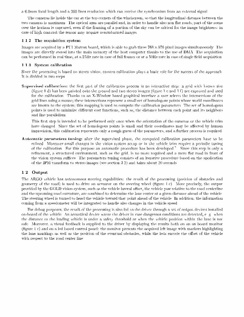
(a) (b) (c)Figure 2. IPM applied to a road environment: (a) 3D representation of the environment, (b) the acquired image,(c) the remapped imageveri�cation of the match with a given surface model su�ces, the application of IPM to stereo images plays a strategicrole.More precisely, since IPM can be used to recover the texture of a speci�c surface (the road plane in the previousdiscussion), when it is applied to both stereo images (with di�erent parameters re ecting the di�erent acquisitionsetup of the two cameras) it provides two instances of the given surface, namely two partially overlapping patches.These two patches, thanks to the knowledge of the vision system setup, can be brought to correspondence, so thatthe homologous points share the same coordinates in the two remapped images.3.3. Lane Detection by means of IPMThis section presents a possible solution to the problem of lane detection in images acquired from a camera installedon a mobile vehicle which is reduced to the detection of lane markings. In this case the a-priori knowledge exploitedby the IMP transform is the assumption of a at road in front of the vehicle. The advantage o�ered by the useof the IPM is that in the remapped image (see �gure 2.c) the road markings width is almost invariant within thewhole image. This simpli�es the following detection steps and allows its implementation with a traditional patternmatching technique on a SIMD system.The basic assumption lane detection relies on is that road markings after the IPM transform are represented byquasi-vertical constant width lines, brighter than their surrounding region. Hence the �rst step of road markingsdetection is a low-level processing aimed to detect the pixels that have a higher brightness value than their horizontalneighbors at a given distance. The following processing is in charge of the reconstruction of the road geometry.3.3.1. Lane Markings DetectionThanks to the removal of the perspective e�ect, in a remapped image lane markings are represented by almost verticalbright lines of constant width, surrounded by a darker background. Thus the �rst phase of lane detection is basedon the search for dark-bright-dark horizontal patterns with a given size. Every pixel is compared to its left and righthorizontal neighbors at a given distance and a new grey-level image is computed. This image encodes the horizontalbrightness transitions and the presence of lane markings. Di�erent illumination conditions, such as shadows orsunny blobs, cause road markings to assume di�erent brightness values; anyway the pixels corresponding to the lanemarkings maintain a brightness value higher than their horizontal neighbors. In addition, taking advantage of lanemarkings vertical correlation, the image is enhanced (�gure 3.a) through few iterations of a geodesic morphologicaldilation.8Di�erent illumination conditions and the nonuniformity of painted road signs require the use of an adaptivethreshold that works on a 3� 3 pixel neighborhood.

(a) (b) (c)(d) (e) (f)Figure 3. The di�erent steps of Lane Detection: (a) enhanced image; (b) binarized image; (c) concatenation ofpixels; (d) segmentation and construction of polylines (e) identi�cation of the centre of the lane; (f) superimpositionof the previous result onto a brighter version of the original image for displaying purposes only3.3.2. Road Geometry ReconstructionThe binary image is thinned and scanned row by row in order to build chains of non-zero pixels.Each chain is approximated with a polyline made of one or more segments, by means of an iterative process; at�rst the two extrema of the polyline are determined At each step of the process the segment being considered iskept as a part of the polyline if the horizontal distance between its middle point and the chain is su�ciently small;otherwise two consecutive segments are examined in its place.To get rid of possible occlusions or errors caused by noise, two or more polylines are joined into longer ones ifthey satisfy some criteria such as small distance between the nearest extrema and similar orientation of the endingsegments. When more solutions are possible in joining the polylines, all of them are considered.A road model is used to select the polyline which most likely matches the center road line. Initially the vehicle isassumed to be a speci�c position (center of the lane) on the road, which, at the same time, is assumed to be almoststraight. In this situation the road center line in the remapped image is a straight vertical line that is expected to befound in a circumscribed area of the remapped image. Each computed polyline is matched against this model usingseveral parameters such as distance, parallelism, orientation, and length. The polyline that �ts better these requiredparameters is selected (�gure 3.e). Finally a new road model is computed using the selected polyline, thus enablingthe system to track the road in image sequences and to adapt the road model also to non-straight roads.Since the model assumed for the external environment ( at road) allows to determine the spatial relationshipbetween image pixels and the 3D world,4 from the previous result it is possible to derive both the road geometryand the vehicle position within the lane. Fig. 3 shows the steps of lane detection for the image shown in �gure 2.Thanks to the IPM transform, the approach has demonstrated its robustness also in the case of shadows, whichrepresents a typical critical condition.93.4. Obstacle Detection by means of Stereo IPMAs mentioned in paragraph 3.2, when obstacle detection means the mere localization of objects that can obstructthe vehicle's path without their complete identi�cation or recognition, stereo IPM can be used in conjunction with a
(a) (b) (c) (d)0
30
6090
120
150
0 30 60 90 120 150Angle of view (degrees)
0.0
0.2
0.4
0.6
0.8
Nu
mb
er
of
no
n-z
ero
pix
els
(n
orm
alize
d)
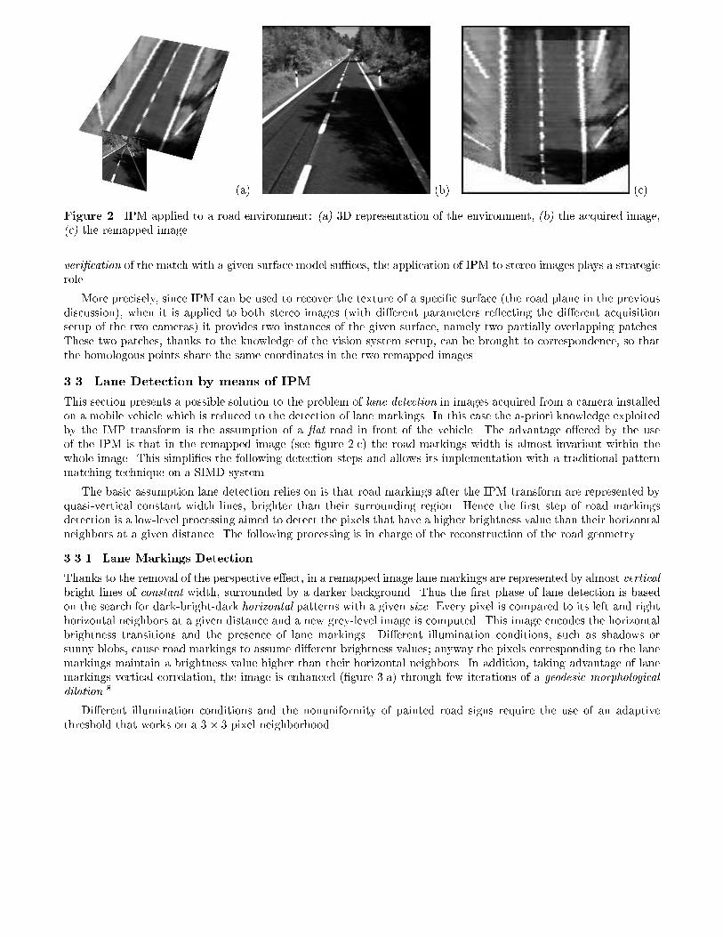
(e) (f) (g) (h)Figure 4. Obstacle detection: (a) left and (b) right stereo images, (c) and (d) the remapped images, (e) the di�erenceimage, (f) the angles of view overlapped with the di�erence image, (g) the polar histogram, and (h) the result ofobstacle detection using a black marker superimposed on a brighter version of the acquired left image; the light grayarea represents the road region visible from both camerasgeometrical model of the road in front of the vehicle.2 Assuming the at road hypothesis introduced in the previoussection, IPM is performed using the same relations. This is of basic importance since in a system aimed to bothobstacle and lane detection the IPM transform can be performed only once and its result can be shared by the twoprocesses. The at road model is checked through a pixel-wise di�erence between the two remapped images: incorrespondence to a generic obstacle in front of the vehicle, namely anything rising up from the road surface, thedi�erence image features su�ciently large clusters of non-zero pixels that have a particular shape.Due to the di�erent angles of view of the stereo cameras, an ideal homogeneous square obstacle produces twoclusters of pixels with a triangular shape in the di�erence image, in correspondence to its vertical edges.Unfortunately triangles found in real cases (see �gure 4) are not so clearly de�ned and often not clearly disjointbecause of the texture, irregular shape, and non-homogeneous color of real obstacles. Nevertheless clusters of pixelshaving an almost triangular shape are anyway recognizable in the di�erence image (see �gure 4.e). The obstacledetection process is thus based on the localization of these triangles.Moreover, this process is complicated by the possible presence of two or more obstacles in front of the vehicle atthe same time, thus producing more than one pair of triangles, or partially visible obstacles, thus producing a singletriangle; a further processing step is thus needed in order to classify triangles that belong to the same obstacle.3.4.1. Obstacle LocalizationA polar histogram is used for the detection of triangles: it is obtained scanning the di�erence image with respect toa focus, considering every straight line originating from the focus itself and counting the number of overthresholdpixels lying on that line (�gure 4.f). The values of the polar histogram are then normalized and a low-pass �lter isapplied in order to decrease the in uence of noise (�gure 4.g). The polar histogram presents an appreciable peakcorresponding to each triangle. Peaks may have di�erent characteristics such as amplitude, sharpness, or width,depending on the obstacle distance, the angle of view, and the di�erence in brightness and texture between thebackground and the obstacle itself. The position of a peak within the histogram determines the angle of view underwhich the obstacle edge is seen. Peaks generated by same obstacle, for example by its left and right edges, must bejoined in order to consider the whole area in between as occluded.
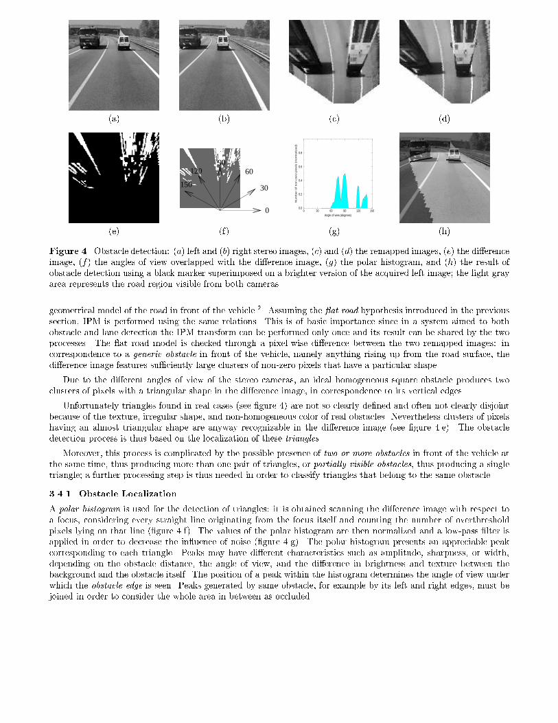
(a) (b) (c) (d)Figure 5. Situations in which lane detection fails: (a) the road has a too high curvature (namely one of the roadmarkings is not visible), thus producing (b) an incomplete remapped image; (c) the road is not at, thus producing(d) an deformed remapped imageStarting from the analysis of a large number of di�erent situations a criterion has been found, aimed to thegrouping of peaks, that takes into account several characteristics such as the peaks amplitude and width, the areathey subtend, as well as the interval between them.After the peaks joining phase, the angle of view under which the whole obstacle is seen is computed consideringthe peaks position, amplitude, and width.In addition, the obstacle distance can be estimated by a further analysis of the di�erence image along the directionspointed out by the maxima of the polar histogram, in order to detect the triangles corners. In fact they representthe contact points between obstacles and the road plane and thus hold the information about the obstacle distance.For each peak of the polar histogram a radial histogram is computed scanning a speci�c sector of the di�erenceimage whose width is determined as a function of the peak width.1 The number of overthreshold pixels lying in thesector is computed for every distance from the focus and the result is normalized. A simple threshold applied to theradial histogram allows to detect the triangles corners position and thus the obstacle distance.The result is displayed with black markers superimposed on a brighter version of the left image; the markersposition and size encode both the distance and width of obstacles (see �gure 4.h).4. DISCUSSIONIn this work the GOLD system for lane and obstacle detection has been presented. It was installed on ARGO andtested on a number of di�erent highways, freeways and country roads in Italy.Di�erent processing systems have been considered to be the hardware support for the GOLD system, both special-purpose and general-purpose. The architecture that is currently installed on ARGO is a Pentium MMX 200 MHz,which delivers very high performances (table 1 compares di�erent hardware con�gurations). All these con�gurationsreach real-time performance: since the acquisition of a single �eld takes 20 ms, as soon as the processing takes lessthan 20 ms it is considered to be working in real-time. In this case, the actual bottleneck of the system is theacquisition device. Obstacle Detection Lane DetectionLow-level Total % Low-Level Low-level Total % Low-LevelPentiumPro (200MHz) 3.6 ms 4.6 ms 78% 4.4 ms 6.4 ms 68%Pentium (200MHz) 7.6 ms 10.0 ms 76% 5.9 ms 8.7 ms 68%Pentium MMX(200MHz) 1.1 ms 5.1 ms 22% 0.8 ms 4.6 ms 17%Table 1. Performance evaluation of obstacle and lane detection algorithm on standard and MMX based architecturesRegarding the qualitative performance of GOLD, obviously, when the initial assumptions are not met, namelywhen road markings are not completely visible due either to occlusions caused by obstacles or to a too high roadcurvature (�g. 5.a) or when the road is not at (�g. 5.c), lane detection cannot produce valid results.

�� � 1�000 �� � 0�300 �� �� + 0�300 �� + 1�000Figure 6. Obstacle detection changing the inclination parameter: di�erence image, polar histogram, and value ofthe inclination parameter
h - 10 cm h - 5 cm h h + 5 cm h + 10 cmFigure 7. Obstacle detection changing the height parameter: di�erence image, polar histogram, and value of theheight parameterOn the other hand, since obstacle detection is based on stereo vision, the quality of the results is tightly coupledalso to the calibration of the vision system. Nevertheless, since in our case the �nal target of obstacle detection is thedetermination of the free space in front of the vehicle and not the complete 3D reconstruction of the world, cameracalibration becomes less critical. For this reason, even if the vehicle's movements in uence some of the calibrationparameters (camera height h and inclination �� with respect of the road plane), a dynamic recalibration of the systemis not required. For comparison purposes the ranging values for cameras height (h� 10 cm) and inclination (��� 1�)larger than the ones estimated by Koller et al.10 have been considered. Fig. 6 and 7 show the results of obstacledetection emulating the changes of cameras parameters caused by vehicle movements: due to the robustness of theapproach based on polar histogram, the obstacle is always detected even if the di�erence images are noisy.The major critical points of obstacle detection were found when:� the obstacle is too far from the cameras (generally it happens in the range 45 � 50 m), thus the polar histogram

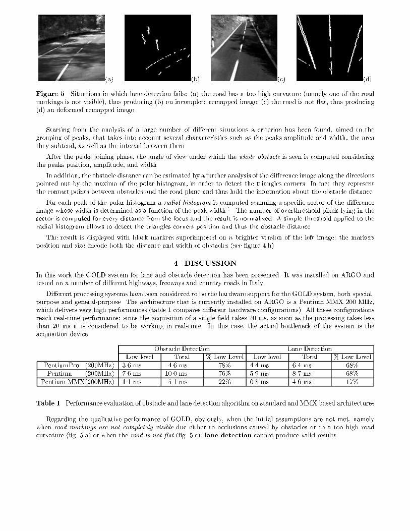
(a) (b) (c) (d)(e) (f) (g) (h)Figure 8. Situations in which obstacle detection is criticalpresents only small and isolated peaks that can be hardly joined (�g. 8.a, 8.b, and 8.c): anyway, when theobstacle distance is in the range 5� 45 m, this problem has never been detected;� the guard-rail is close to the obstacle and thus a single large obstacle is detected (�g. 8.d);� an obstacle is partially visible, and thus only one of its edges can be detected (�g. 8.d and 8.e);� some noisy peaks in the polar histogram are not �ltered out, and thus they are considered as small obstacles(�g. 8.f and 8.g)� the detection of far obstacles sometimes fails when their brightnesses is similar to the brightnesses of the road(�g. 8.h).The con�dence in the detection of obstacles is obviously dependent on their size, distance, and shape; speci�cparameters are used to tune the system sensitivity.Obstacle height: the obstacle height determines the amplitude of peaks in the polar histogram. The bandwidth ofthe LPF applied to the polar histogram is the parameter used as threshold to discard small peaks that could becaused by either noise or short obstacles: the smaller the bandwidth, the lower the in uence of noise (caused byincorrect camera calibration or vehicle movements), but the larger the minimum height of detectable obstacles(in �g. 8.c and 8.d the guard-rail is detected even if it is not as tall as vehicles).Obstacle width: in the polar histogram two or more peaks are joined when they are su�ciently close to each otherand present similar height. The threshold used in this phase modi�es the width of the wider correctly detectableobject, and also the probability that peaks not generated by the same obstacle are joined (see �g. 8.d).Obstacle distance: the farther the obstacle, the smaller the triangles generated in the di�erence image, and thusthe lower the amplitude of peaks in the polar histogram; nevertheless, for su�ciently tall obstacles (e.g. vehiclesat about 50 m far from the cameras) the main problem is not the detection of peaks, but their joining, as shownin �g. 8.a, b, and c.Obstacle shape: the algorithm was designed to detect obstacles with quasi-vertical edges; objects with non-verticaledges (e.g. pyramidal objects) generate twisted triangles that are hardly detected by the analysis of the polarhistogram.Also the inter-camera spacing is a key parameter: the greater the distance between cameras, the stronger the dis-parities in the remapped images due to the presence of an obstacle. Nevertheless the inter-camera spacing is bounded

by the vehicle physical structure, thus the cameras were installed at the maximum allowed distance. Unfortunately,a too large separation leads to a higher sensitivity to vehicle movements, in particular rolling.During the tests, the system demonstrated to be robust and reliable: other vehicles were always detected andonly in few cases (i.e. on paved or -more generally- rough roads) vehicle movements became so considerable thatthe processing of noisy remapped images led to the erroneous detection of false small sized obstacles. Nevertheless,since the vehicle's movements have a small frequency, these small-sized obstacles appear only in very few consecutiveframes, and can be easily removed thanks to a temporal averaging �lter.On the other hand, thanks to the remapping process, lane markings were located even in presence of shadowsor other artifacts on the road surface; anyway, although it is hard to devise a method to evaluate the percentage ofsuccessful lane detection, some uno�cial tests� showed that the system detects the correct position of the lane inabout 95 % of the considered situations.An extension to the IPM technique is now under evaluation: thanks to the information obtained from pairs ofstereo images, it is possible to derive the height of homologous points in the image using simple triangulations. Thealgorithm selects features of the image that belong to the road plane (in this implementation it selects road markings)and determines their height with respect to a at road model. In this way it is possible to measure the road slopeand recalibrate the IPM procedure according to the new road model. The road model is updated once every 20-30frames (about once per second)Moreover, an extension to the GOLD system able to exploit temporal correlations and to perform a deeper data-fusion between the two functionalities of lane detection and obstacle detection is currently under implementation11on ARGO. REFERENCES1. M. Bertozzi and A. Broggi, \GOLD: a Parallel Real-Time Stereo Vision System for Generic Obstacle and LaneDetection," IEEE Transactions on Image Processing 7, pp. 62{81, January 1998.2. M. Bertozzi, A. Broggi, and A. Fascioli, \Stereo Inverse Perspective Mapping: Theory and Applications," Imageand Vision Computing Journal , 1998.3. Intel Corporation, MMX Technology Programmers Reference Manual. Intel Corporation, 1997. avalaible athttp://www.intel.com.4. H. A. Mallot, H. H. B�ultho�, J. J. Little, and S. Bohrer, \Inverse perspective mapping simpli�es optical owcomputation and obstacle detection," Biological Cybernetics 64, pp. 177{185, 1991.5. D. A. Pomerleau, \RALPH: Rapidly Adapting Lateral Position Handler," in Proceedings IEEE Intelligent Ve-hicles'95, I. Masaky, ed., pp. 506{511, IEEE Computer Society, (Detroit), September 25-26 1995.6. K. Storjohann, T. Zielke, H. A. Mallot, and W. von Seelen, \Visual Obstacle Detection for Automatically GuidedVehicle," in Proceedings of IEEE International Conference on Robotics and Automation, vol. II, pp. 761{766,1990.7. O. Faugeras, Three-Dimensional Computer Vision: A Geometric Viewpoint, The MIT Press, 1993.8. J. Serra, Image Analysis and Mathematical Morphology, Academic Press, London, 1982.9. A. Broggi and S. Bert�e, \Vision-Based Road Detection in Automotive Systems: a Real-Time Expectation-DrivenApproach," Journal of Arti�cial Intelligence Research 3, pp. 325{348, December 1995.10. D. Koller, J. Malik, Q.-T. Luong, and J. Weber, \An integrated stereo-based approach to automatic vehicleguidance," in Proceedings of the Fifth ICCV, pp. 12{20, (Boston), 1995.11. M. Bertozzi, A. Broggi, and A. Fascioli, \Obstacle and Lane Detection on ARGO," in Proceedings IEEE Intel-ligent Transportation Systems Conference'97, (Boston, USA), November 1997.�these results do not take into account an exhaustive set of road conditions.