a programming language for composable dna circuits - …lucacardelli.name/papers/a programming...
TRANSCRIPT
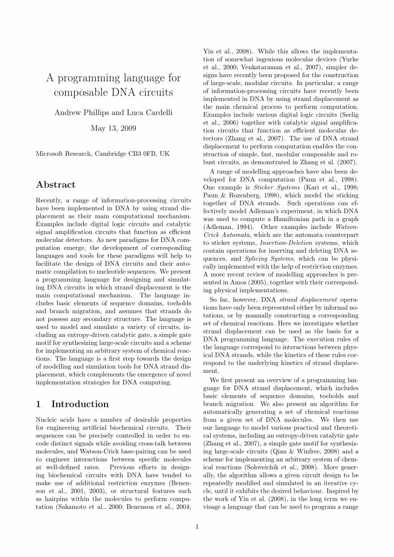
A programming language forcomposable DNA circuits
Andrew Phillips and Luca Cardelli
May 13, 2009
Microsoft Research, Cambridge CB3 0FB, UK
Abstract
Recently, a range of information-processing circuitshave been implemented in DNA by using strand dis-placement as their main computational mechanism.Examples include digital logic circuits and catalyticsignal amplification circuits that function as efficientmolecular detectors. As new paradigms for DNA com-putation emerge, the development of correspondinglanguages and tools for these paradigms will help tofacilitate the design of DNA circuits and their auto-matic compilation to nucleotide sequences. We presenta programming language for designing and simulat-ing DNA circuits in which strand displacement is themain computational mechanism. The language in-cludes basic elements of sequence domains, toeholdsand branch migration, and assumes that strands donot possess any secondary structure. The language isused to model and simulate a variety of circuits, in-cluding an entropy-driven catalytic gate, a simple gatemotif for synthesizing large-scale circuits and a schemefor implementing an arbitrary system of chemical reac-tions. The language is a first step towards the designof modelling and simulation tools for DNA strand dis-placement, which complements the emergence of novelimplementation strategies for DNA computing.
1 Introduction
Nucleic acids have a number of desirable propertiesfor engineering artificial biochemical circuits. Theirsequences can be precisely controlled in order to en-code distinct signals while avoiding cross-talk betweenmolecules, and Watson-Crick base-pairing can be usedto engineer interactions between specific moleculesat well-defined rates. Previous efforts in design-ing biochemical circuits with DNA have tended tomake use of additional restriction enzymes (Benen-son et al., 2001, 2003), or structural features suchas hairpins within the molecules to perform compu-tation (Sakamoto et al., 2000; Benenson et al., 2004;
Yin et al., 2008). While this allows the implementa-tion of somewhat ingenious molecular devices (Yurkeet al., 2000; Venkataraman et al., 2007), simpler de-signs have recently been proposed for the constructionof large-scale, modular circuits. In particular, a rangeof information-processing circuits have recently beenimplemented in DNA by using strand displacement asthe main chemical process to perform computation.Examples include various digital logic circuits (Seeliget al., 2006) together with catalytic signal amplifica-tion circuits that function as efficient molecular de-tectors (Zhang et al., 2007). The use of DNA stranddisplacement to perform computation enables the con-struction of simple, fast, modular composable and ro-bust circuits, as demonstrated in Zhang et al. (2007).
A range of modelling approaches have also been de-veloped for DNA computation (Paun et al., 1998).One example is Sticker Systems (Kari et al., 1998;Paun & Rozenberg, 1998), which model the stickingtogether of DNA strands. Such operations can ef-fectively model Adleman’s experiment, in which DNAwas used to compute a Hamiltonian path in a graph(Adleman, 1994). Other examples include Watson-Crick Automata, which are the automata counterpartto sticker systems, Insertion-Deletion systems, whichcontain operations for inserting and deleting DNA se-quences, and Splicing Systems, which can be physi-cally implemented with the help of restriction enzymes.A more recent review of modelling approaches is pre-sented in Amos (2005), together with their correspond-ing physical implementations.
So far, however, DNA strand displacement opera-tions have only been represented either by informal no-tations, or by manually constructing a correspondingset of chemical reactions. Here we investigate whetherstrand displacement can be used as the basis for aDNA programming language. The execution rules ofthe language correspond to interactions between phys-ical DNA strands, while the kinetics of these rules cor-respond to the underlying kinetics of strand displace-ment.
We first present an overview of a programming lan-guage for DNA strand displacement, which includesbasic elements of sequence domains, toeholds andbranch migration. We also present an algorithm forautomatically generating a set of chemical reactionsfrom a given set of DNA molecules. We then useour language to model various practical and theoreti-cal systems, including an entropy-driven catalytic gate(Zhang et al., 2007), a simple gate motif for synthesiz-ing large-scale circuits (Qian & Winfree, 2008) and ascheme for implementing an arbitrary system of chem-ical reactions (Soloveichik et al., 2008). More gener-ally, the algorithm allows a given circuit design to berepeatedly modified and simulated in an iterative cy-cle, until it exhibits the desired behaviour. Inspired bythe work of Yin et al. (2008), in the long term we en-visage a language that can be used to program a range
1
of DNA molecules, simulate their behaviour, and thenautomatically generate the corresponding nucleic acidsequences, ready for synthesis.
2 Results
2.1 A language for DNA strand dis-placement
Simple examples
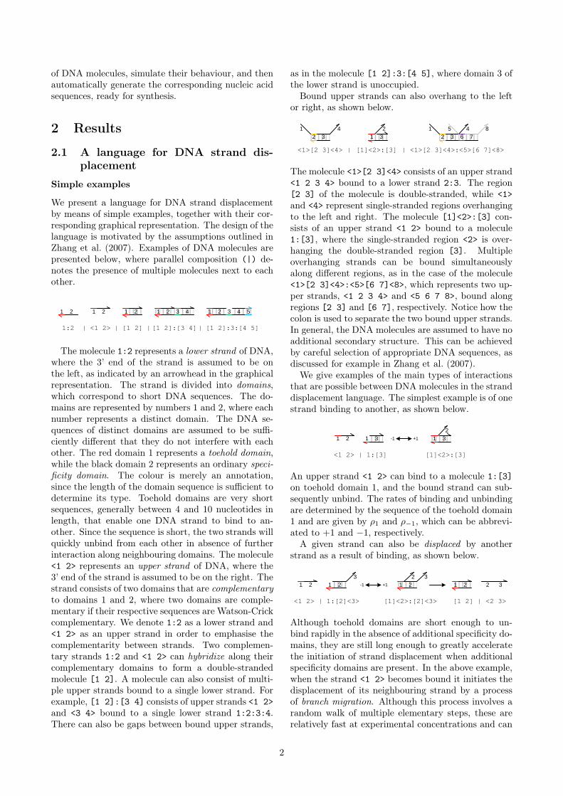
We present a language for DNA strand displacementby means of simple examples, together with their cor-responding graphical representation. The design of thelanguage is motivated by the assumptions outlined inZhang et al. (2007). Examples of DNA molecules arepresented below, where parallel composition (|) de-notes the presence of multiple molecules next to eachother.
21 2
<1 2>
1 2 1
[1 2]
21
[1 2]:[3 4]
43 21
[1 2]:3:[4 5]|1:2 | | |
43 5
The molecule 1:2 represents a lower strand of DNA,where the 3’ end of the strand is assumed to be onthe left, as indicated by an arrowhead in the graphicalrepresentation. The strand is divided into domains,which correspond to short DNA sequences. The do-mains are represented by numbers 1 and 2, where eachnumber represents a distinct domain. The DNA se-quences of distinct domains are assumed to be suffi-ciently different that they do not interfere with eachother. The red domain 1 represents a toehold domain,while the black domain 2 represents an ordinary speci-ficity domain. The colour is merely an annotation,since the length of the domain sequence is sufficient todetermine its type. Toehold domains are very shortsequences, generally between 4 and 10 nucleotides inlength, that enable one DNA strand to bind to an-other. Since the sequence is short, the two strands willquickly unbind from each other in absence of furtherinteraction along neighbouring domains. The molecule<1 2> represents an upper strand of DNA, where the3’ end of the strand is assumed to be on the right. Thestrand consists of two domains that are complementaryto domains 1 and 2, where two domains are comple-mentary if their respective sequences are Watson-Crickcomplementary. We denote 1:2 as a lower strand and<1 2> as an upper strand in order to emphasise thecomplementarity between strands. Two complemen-tary strands 1:2 and <1 2> can hybridize along theircomplementary domains to form a double-strandedmolecule [1 2]. A molecule can also consist of multi-ple upper strands bound to a single lower strand. Forexample, [1 2]:[3 4] consists of upper strands <1 2>and <3 4> bound to a single lower strand 1:2:3:4.There can also be gaps between bound upper strands,
as in the molecule [1 2]:3:[4 5], where domain 3 ofthe lower strand is unoccupied.
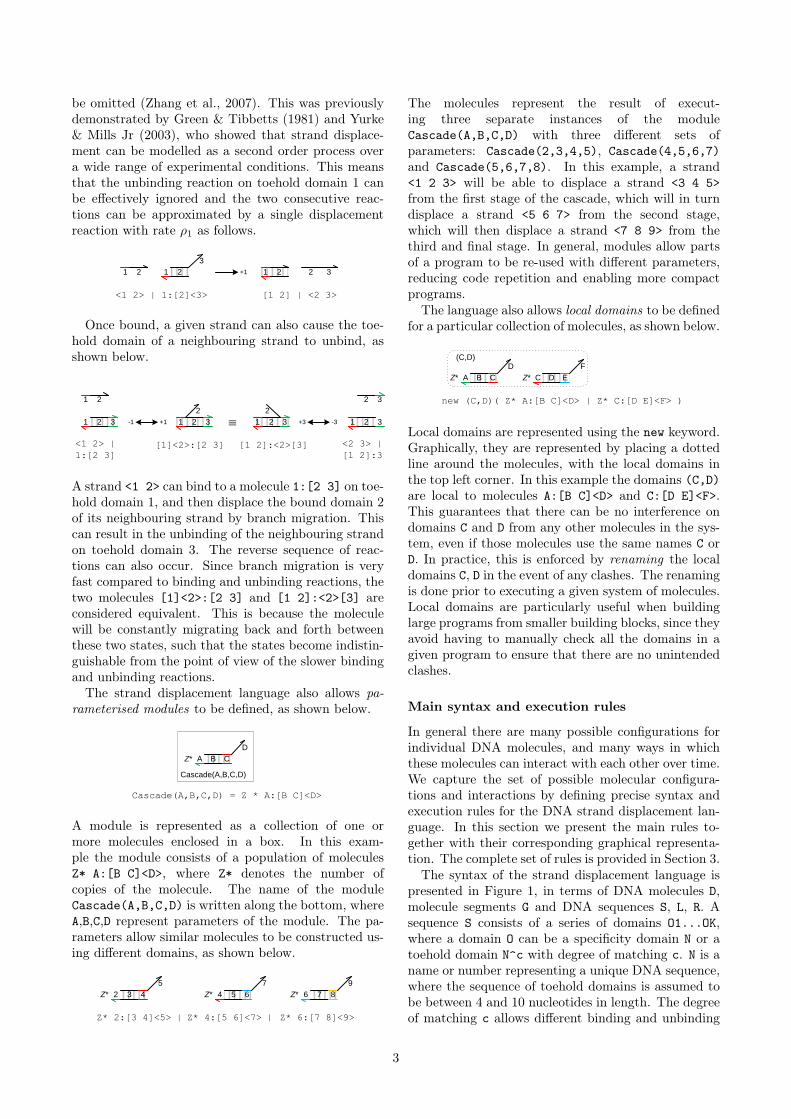
Bound upper strands can also overhang to the leftor right, as shown below.
<1>[2 3]<4>
32
|
1 4
32
1 4
76
5 8
<1>[2 3]<4>:<5>[6 7]<8>|
1
2
[1]<2>:[3]
3
The molecule <1>[2 3]<4> consists of an upper strand<1 2 3 4> bound to a lower strand 2:3. The region[2 3] of the molecule is double-stranded, while <1>and <4> represent single-stranded regions overhangingto the left and right. The molecule [1]<2>:[3] con-sists of an upper strand <1 2> bound to a molecule1:[3], where the single-stranded region <2> is over-hanging the double-stranded region [3]. Multipleoverhanging strands can be bound simultaneouslyalong different regions, as in the case of the molecule<1>[2 3]<4>:<5>[6 7]<8>, which represents two up-per strands, <1 2 3 4> and <5 6 7 8>, bound alongregions [2 3] and [6 7], respectively. Notice how thecolon is used to separate the two bound upper strands.In general, the DNA molecules are assumed to have noadditional secondary structure. This can be achievedby careful selection of appropriate DNA sequences, asdiscussed for example in Zhang et al. (2007).
We give examples of the main types of interactionsthat are possible between DNA molecules in the stranddisplacement language. The simplest example is of onestrand binding to another, as shown below.
1 2
<1 2> | 1:[3]
1 1
2
[1]<2>:[3]
+1-13 3
An upper strand <1 2> can bind to a molecule 1:[3]on toehold domain 1, and the bound strand can sub-sequently unbind. The rates of binding and unbindingare determined by the sequence of the toehold domain1 and are given by ρ1 and ρ−1, which can be abbrevi-ated to +1 and −1, respectively.
A given strand can also be displaced by anotherstrand as a result of binding, as shown below.
21 2
<1 2> | 1:[2]<3>
1
3
1
[1]<2>:[2]<3> [1 2] | <2 3>
+1-12 1
2 3
2 32
Although toehold domains are short enough to un-bind rapidly in the absence of additional specificity do-mains, they are still long enough to greatly acceleratethe initiation of strand displacement when additionalspecificity domains are present. In the above example,when the strand <1 2> becomes bound it initiates thedisplacement of its neighbouring strand by a processof branch migration. Although this process involves arandom walk of multiple elementary steps, these arerelatively fast at experimental concentrations and can
2
be omitted (Zhang et al., 2007). This was previouslydemonstrated by Green & Tibbetts (1981) and Yurke& Mills Jr (2003), who showed that strand displace-ment can be modelled as a second order process overa wide range of experimental conditions. This meansthat the unbinding reaction on toehold domain 1 canbe effectively ignored and the two consecutive reac-tions can be approximated by a single displacementreaction with rate ρ1 as follows.
21 2
<1 2> | 1:[2]<3>
1
3
1
[1 2] | <2 3>
+12 32
Once bound, a given strand can also cause the toe-hold domain of a neighbouring strand to unbind, asshown below.
1 2
<1 2> |
1:[2 3]
1
[1]<2>:[2 3] [1 2]:<2>[3]
+1-12 1
2
2
32
3 3 1 2 3º2
-3+3 1 2 3
<2 3> |
[1 2]:3
A strand <1 2> can bind to a molecule 1:[2 3] on toe-hold domain 1, and then displace the bound domain 2of its neighbouring strand by branch migration. Thiscan result in the unbinding of the neighbouring strandon toehold domain 3. The reverse sequence of reac-tions can also occur. Since branch migration is veryfast compared to binding and unbinding reactions, thetwo molecules [1]<2>:[2 3] and [1 2]:<2>[3] areconsidered equivalent. This is because the moleculewill be constantly migrating back and forth betweenthese two states, such that the states become indistin-guishable from the point of view of the slower bindingand unbinding reactions.
The strand displacement language also allows pa-rameterised modules to be defined, as shown below.
A B C
Cascade(A,B,C,D)
D
Cascade(A,B,C,D) = Z * A:[B C]<D>
Z*
A module is represented as a collection of one ormore molecules enclosed in a box. In this exam-ple the module consists of a population of moleculesZ* A:[B C]<D>, where Z* denotes the number ofcopies of the molecule. The name of the moduleCascade(A,B,C,D) is written along the bottom, whereA,B,C,D represent parameters of the module. The pa-rameters allow similar molecules to be constructed us-ing different domains, as shown below.
2 3 4
5
Z*
Z* 2:[3 4]<5>
4 5 6
7
Z* 6 7 8
9
Z*
Z* 4:[5 6]<7> Z* 6:[7 8]<9>| |
The molecules represent the result of execut-ing three separate instances of the moduleCascade(A,B,C,D) with three different sets ofparameters: Cascade(2,3,4,5), Cascade(4,5,6,7)and Cascade(5,6,7,8). In this example, a strand<1 2 3> will be able to displace a strand <3 4 5>from the first stage of the cascade, which will in turndisplace a strand <5 6 7> from the second stage,which will then displace a strand <7 8 9> from thethird and final stage. In general, modules allow partsof a program to be re-used with different parameters,reducing code repetition and enabling more compactprograms.
The language also allows local domains to be definedfor a particular collection of molecules, as shown below.
A B C
D
Z*
new (C,D)( Z* A:[B C]<D> | Z* C:[D E]<F> )
C D E
F
Z*
(C,D)
Local domains are represented using the new keyword.Graphically, they are represented by placing a dottedline around the molecules, with the local domains inthe top left corner. In this example the domains (C,D)are local to molecules A:[B C]<D> and C:[D E]<F>.This guarantees that there can be no interference ondomains C and D from any other molecules in the sys-tem, even if those molecules use the same names C orD. In practice, this is enforced by renaming the localdomains C, D in the event of any clashes. The renamingis done prior to executing a given system of molecules.Local domains are particularly useful when buildinglarge programs from smaller building blocks, since theyavoid having to manually check all the domains in agiven program to ensure that there are no unintendedclashes.
Main syntax and execution rules
In general there are many possible configurations forindividual DNA molecules, and many ways in whichthese molecules can interact with each other over time.We capture the set of possible molecular configura-tions and interactions by defining precise syntax andexecution rules for the DNA strand displacement lan-guage. In this section we present the main rules to-gether with their corresponding graphical representa-tion. The complete set of rules is provided in Section 3.
The syntax of the strand displacement language ispresented in Figure 1, in terms of DNA molecules D,molecule segments G and DNA sequences S, L, R. Asequence S consists of a series of domains O1...OK,where a domain O can be a specificity domain N or atoehold domain N^c with degree of matching c. N is aname or number representing a unique DNA sequence,where the sequence of toehold domains is assumed tobe between 4 and 10 nucleotides in length. The degreeof matching c allows different binding and unbinding
3
N^c
Nc
Lower strand with toehold Nc
S
RL
<L>[S]<R>
Double strand with sequence S
and overhangs L, R
S
G1 G2 ... GK
G1:G2:...:GK
<S>
Upper strand with sequence
complementary to S
Molecule with segments G1,...,GK
D1 D2 ... DK
D1 | D2 | ... | DK
Parallel molecules D1,...,DK
O1 O2 ... OK
O1 O2 ... OK
Sequence of domains O1,...,OK
A. Syntax of DNA molecules D B. Syntax of DNA segments G
C. Syntax of DNA sequences S,L,R
new (N1,...,NK) D
Molecules D with private domains N1,...,NK
(N1,...,NK)D
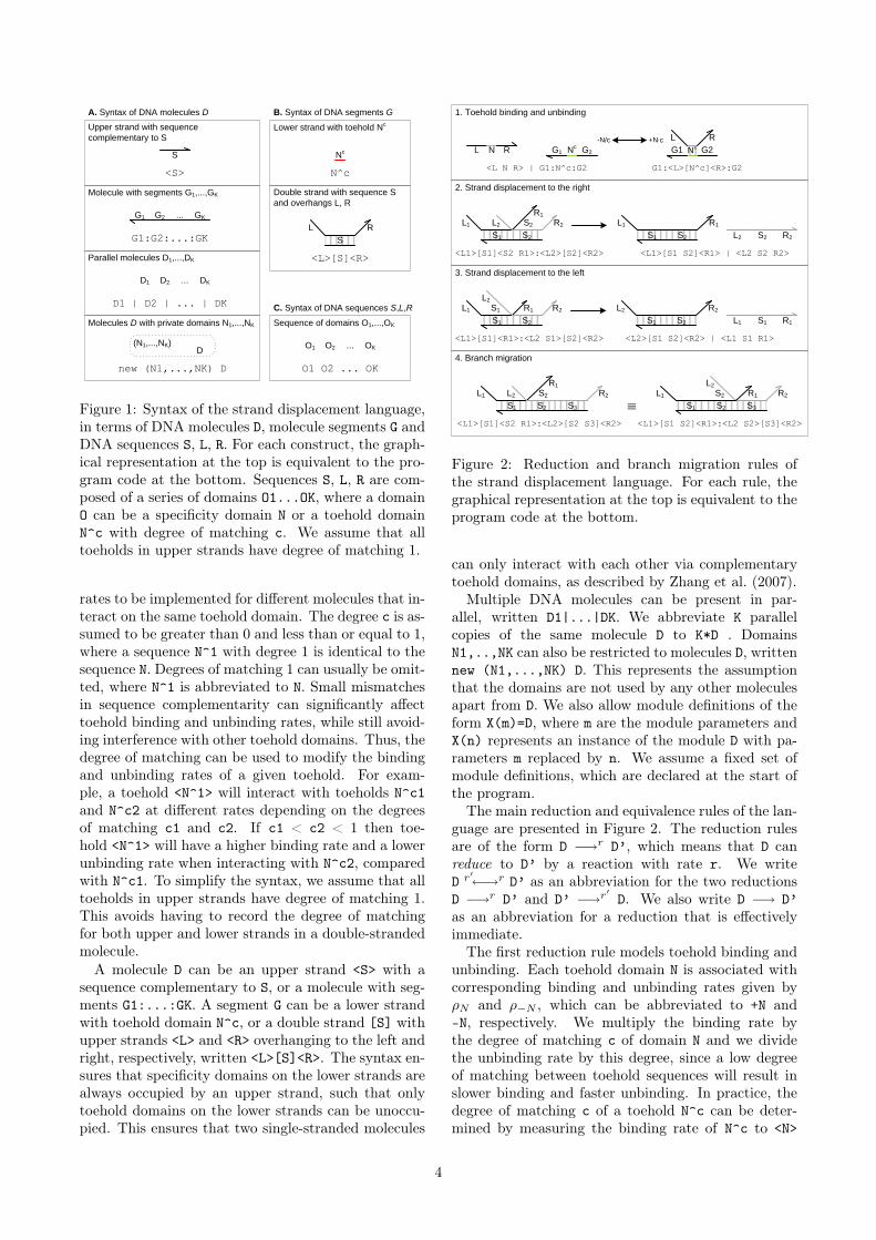
Figure 1: Syntax of the strand displacement language,in terms of DNA molecules D, molecule segments G andDNA sequences S, L, R. For each construct, the graph-ical representation at the top is equivalent to the pro-gram code at the bottom. Sequences S, L, R are com-posed of a series of domains O1...OK, where a domainO can be a specificity domain N or a toehold domainN^c with degree of matching c. We assume that alltoeholds in upper strands have degree of matching 1.
rates to be implemented for different molecules that in-teract on the same toehold domain. The degree c is as-sumed to be greater than 0 and less than or equal to 1,where a sequence N^1 with degree 1 is identical to thesequence N. Degrees of matching 1 can usually be omit-ted, where N^1 is abbreviated to N. Small mismatchesin sequence complementarity can significantly affecttoehold binding and unbinding rates, while still avoid-ing interference with other toehold domains. Thus, thedegree of matching can be used to modify the bindingand unbinding rates of a given toehold. For exam-ple, a toehold <N^1> will interact with toeholds N^c1and N^c2 at different rates depending on the degreesof matching c1 and c2. If c1 < c2 < 1 then toe-hold <N^1> will have a higher binding rate and a lowerunbinding rate when interacting with N^c2, comparedwith N^c1. To simplify the syntax, we assume that alltoeholds in upper strands have degree of matching 1.This avoids having to record the degree of matchingfor both upper and lower strands in a double-strandedmolecule.
A molecule D can be an upper strand <S> with asequence complementary to S, or a molecule with seg-ments G1:...:GK. A segment G can be a lower strandwith toehold domain N^c, or a double strand [S] withupper strands <L> and <R> overhanging to the left andright, respectively, written <L>[S]<R>. The syntax en-sures that specificity domains on the lower strands arealways occupied by an upper strand, such that onlytoehold domains on the lower strands can be unoccu-pied. This ensures that two single-stranded molecules
S2
N RL Nc
G2G1 Nc
L R
G2G1
S1
L1 S2
R1
L2 R2
R2L2S2S1
L1 R1
S2
+N×c-N/c
1. Toehold binding and unbinding
S2S1
L1 R1S1 R2
R1L1S2S1
L2 R2
S1
2. Strand displacement to the right
L2
3. Strand displacement to the left
S2S1
L1 S2
R1
L2 R2
ºS3 S2S1
L1 S2
L2
R2
S3
R1
4. Branch migration
<L1>[S1]<S2 R1>:<L2>[S2]<R2> <L1>[S1 S2]<R1> | <L2 S2 R2>
<L1>[S1]<R1>:<L2 S1>[S2]<R2> <L2>[S1 S2]<R2> | <L1 S1 R1>
<L1>[S1]<S2 R1>:<L2>[S2 S3]<R2> <L1>[S1 S2]<R1>:<L2 S2>[S3]<R2>
<L N R> | G1:N^c:G2 G1:<L>[N^c]<R>:G2
Figure 2: Reduction and branch migration rules ofthe strand displacement language. For each rule, thegraphical representation at the top is equivalent to theprogram code at the bottom.
can only interact with each other via complementarytoehold domains, as described by Zhang et al. (2007).
Multiple DNA molecules can be present in par-allel, written D1|...|DK. We abbreviate K parallelcopies of the same molecule D to K*D . DomainsN1,..,NK can also be restricted to molecules D, writtennew (N1,...,NK) D. This represents the assumptionthat the domains are not used by any other moleculesapart from D. We also allow module definitions of theform X(m)=D, where m are the module parameters andX(n) represents an instance of the module D with pa-rameters m replaced by n. We assume a fixed set ofmodule definitions, which are declared at the start ofthe program.
The main reduction and equivalence rules of the lan-guage are presented in Figure 2. The reduction rulesare of the form D −→r D’, which means that D canreduce to D’ by a reaction with rate r. We writeD r′←→r D’ as an abbreviation for the two reductionsD −→r D’ and D’ −→r′ D. We also write D −→ D’as an abbreviation for a reduction that is effectivelyimmediate.
The first reduction rule models toehold binding andunbinding. Each toehold domain N is associated withcorresponding binding and unbinding rates given byρN and ρ−N , which can be abbreviated to +N and-N, respectively. We multiply the binding rate bythe degree of matching c of domain N and we dividethe unbinding rate by this degree, since a low degreeof matching between toehold sequences will result inslower binding and faster unbinding. In practice, thedegree of matching c of a toehold N^c can be deter-mined by measuring the binding rate of N^c to <N>
4

and dividing by the binding rate of N^1 to <N>. Thenext two rules model a strand being displaced froma molecule to the right and left. The reductions areimmediate, since branch migration is considered tobe much faster than toehold binding or unbinding.The fourth rule models equivalence of molecules upto branch migration. Since a given DNA molecule canrapidly sample its space of possible configurations bybranch migration, the different configurations are con-sidered to represent the same molecule.
We can use the reduction rules of the language togenerate the set of all possible reactions for a givenset of DNA molecules. Essentially, this is achievedby repeated application of the reduction rules to themolecules, where each application of a rule correspondsto a reaction. The rules are repeatedly applied untilno new reactions are generated. The algorithm is pre-sented in more detail in Section 3. The strand displace-ment language can be used to construct an initial setof DNA molecules, and then to automatically deter-mine the set of all possible interactions between thesemolecules over time, together with their correspond-ing interaction rates. We illustrate the application ofthe strand displacement language to three main casesstudies.
2.2 Case study: entropy-driven cat-alytic gate
This case study uses the strand displacement lan-guage to implement an entropy-driven catalytic gatedeveloped by Zhang et al. (2007). The gate enableskey functions of signal amplification and circuit gain,which are essential for implementing large cascadedcircuits in DNA. According to Zhang et al. (2007), thegate is substantially simpler, faster, better understoodand more modular than previous DNA hybridizationdesigns.
Figure 3 presents an implementation of the entropy-driven catalytic gate of Zhang et al. (2007) in thestrand displacement language. The gate consists ofinitial concentrations of fuel, catalyst and substratemolecules. The full sets of species and reactions for thegate are presented in Figure 4. These were compiledfrom the molecules of Figure 3 using the algorithm de-scribed in Section 3. From the compiled reactions weobserve that Catalyst C binds to Substrate S, causingthe release of Signal SB and Output OB in the pres-ence of Fuel F. The same catalyst can be re-used todrive the release of multiple signal and output strands,provided sufficient substrate and fuel molecules arepresent. Thus, the compiled reactions serve as an ini-tial validation of the catalytic gate design.
Note that the compiled reactions of Figure 4 differfrom the manually-defined reactions of Zhang et al.(2007). A comparison between the two sets of reactionsis given in Figure 5. A non-catalytic reaction S+F k0−→OB + SB +W was also given in Zhang et al. (2007),
542
1 6
33 42 4 5
Catalytic
PS*PF* PC*
Catalytic =( PF * <2 3 4> | PC * <4 5> | PS * <1>[2]:<6>[3 4]:5 )
Figure 3: An implementation of the entropy-drivencatalytic gate of Zhang et al. (2007) in the stranddisplacement language. The gate consists of Fuel<2 3 4> Catalyst <4 5> and Substrate molecules<1>[2]:<6>[3 4]:5, at initial concentrations given byPF, PC and PS, respectively.
+3
-3
+3
42
1 6 4
3 42
1 6 4
542
1 6
42
1 2
42
42
5
5
3 5
33
5
5
3
3
4
3 42 3 46
21
4
42
1 2
53
4
Substrate S
Fuel F
Intermediate I1
Waste W
Signal SB
Output OB
4 5
Catalyst C
Intermediate I4
Intermediate I5
3 42
1
5
Intermediate I3
º
+5
-5
+5
-5
º
C = <4 5> S = <1>[2]:<6>[3 4]:5SB = <6 3 4> I1 = <1>[2]:<6>[3]<4>:[4 5]F = <2 3 4> I3 = <1>[2]:3:[4 5]OB = <1 2> I4 = <1>[2]:<2>[3]<4>:[4 5]W = [2 3 4 ]:5 I5 = [2 3 4]:<4>[5]
S + C {rm5}<->{r5} I1 I1 {r3}<->{rm3} I3 + SBI3 + F ->{r3} I4 I4 -> I5 + OBI5 {r5}<->{rm5} C + W
Figure 4: Species and reactions for the entropy-drivencatalytic gate of Zhang et al. (2007). Starting fromthe molecules of Figure 3, the full set of species andreactions were compiled using the algorithm describedin Section 3. Species are given unique identifiers toallow a more compact representation of reactions. Herethe species identifiers were chosen to be the same as inZhang et al. (2007).
but the rate k0 was considered to be negligible andcan be effectively ignored. Both models also assumethe presence of excess reporter molecules SR and OR,which detect the signals SB and OB, respectively, as
5
S + Ck1k−1
I3 + SB (1)
I3 + Fk2−→ I5 + OB (2)
I5k3k−3
C + W (3)
S + Cρ5ρ−5
I1ρ−3ρ3
I3 +SB(4)
I3 + Fρ3−→ I4→I5 + OB (5)
I5ρ−5ρ5
C + W (6)
Figure 5: Comparison between the manually-definedreactions of Zhang et al. (2007), shown on the left,and the compiled reactions of Figure 4, shown on theright.
follows:
SB + SRkT ET−→ TET (7)
OB +ORkT ET−→ ROX (8)
The reporter SR binds to the signal SB causing therelease of the green tetrachlorofluorescein (TET ) flu-orophore, while the reporter OR binds to the outputOB causing the release of the red carboxy-Xrhodamine(ROX) fluorophore. Thus, the level of green and redfluorescence can be used to measure of the concentra-tion of signal and output strands, respectively.
The remaining reactions in Zhang et al. (2007) as-sume that the binding rate for S and C is the sameas the binding rate for C and W , since both reactionsinvolve the same toehold sequence 5. Similarly, thebinding rate of I3 and SB is assumed to be the sameas the binding rate of I3 and F . Thus, k1 = k−3 = ρ5
and k−1 = k2 = ρ3. This is consistent with the reduc-tion rules of the strand displacement language, whichassume that interactions on the same toehold occur atthe same rate.
For (5), since strand displacement is assumed to bemuch faster than toehold unbinding, the unbinding re-action on toehold 3 is effectively ignored, which is con-sistent with (2). This assumption was previously dis-cussed in Section 2.1. For (4), the original reactionsignored the formation of the intermediate complex I1,resulting in the approximation (1). The toehold un-binding reaction ρ−3 is considered to be quite fast,since toehold 3 is deliberately shortened to acceler-ate strand unbinding. However, the original reactionsdo not explicitly take into account the constraints be-tween ρ−3 and ρ−5. According to our reactions, therate of unbinding of toehold 3 must be significantlyfaster than the rate of unbinding of toehold 5, and wecan simulate the effects of different unbinding rates forthese toeholds.
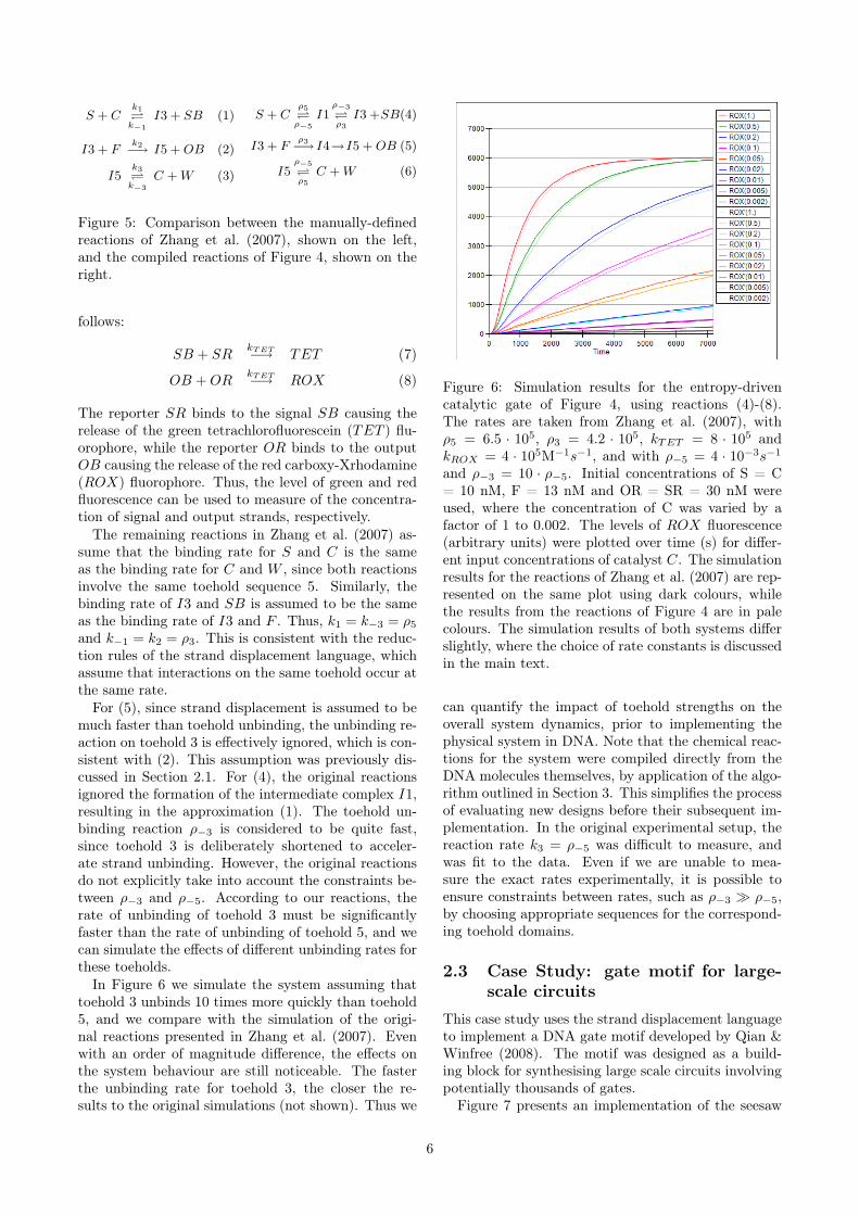
In Figure 6 we simulate the system assuming thattoehold 3 unbinds 10 times more quickly than toehold5, and we compare with the simulation of the origi-nal reactions presented in Zhang et al. (2007). Evenwith an order of magnitude difference, the effects onthe system behaviour are still noticeable. The fasterthe unbinding rate for toehold 3, the closer the re-sults to the original simulations (not shown). Thus we
Figure 6: Simulation results for the entropy-drivencatalytic gate of Figure 4, using reactions (4)-(8).The rates are taken from Zhang et al. (2007), withρ5 = 6.5 · 105, ρ3 = 4.2 · 105, kTET = 8 · 105 andkROX = 4 · 105M−1s−1, and with ρ−5 = 4 · 10−3s−1
and ρ−3 = 10 · ρ−5. Initial concentrations of S = C= 10 nM, F = 13 nM and OR = SR = 30 nM wereused, where the concentration of C was varied by afactor of 1 to 0.002. The levels of ROX fluorescence(arbitrary units) were plotted over time (s) for differ-ent input concentrations of catalyst C. The simulationresults for the reactions of Zhang et al. (2007) are rep-resented on the same plot using dark colours, whilethe results from the reactions of Figure 4 are in palecolours. The simulation results of both systems differslightly, where the choice of rate constants is discussedin the main text.
can quantify the impact of toehold strengths on theoverall system dynamics, prior to implementing thephysical system in DNA. Note that the chemical reac-tions for the system were compiled directly from theDNA molecules themselves, by application of the algo-rithm outlined in Section 3. This simplifies the processof evaluating new designs before their subsequent im-plementation. In the original experimental setup, thereaction rate k3 = ρ−5 was difficult to measure, andwas fit to the data. Even if we are unable to mea-sure the exact rates experimentally, it is possible toensure constraints between rates, such as ρ−3 � ρ−5,by choosing appropriate sequences for the correspond-ing toehold domains.
2.3 Case Study: gate motif for large-scale circuits
This case study uses the strand displacement languageto implement a DNA gate motif developed by Qian &Winfree (2008). The motif was designed as a build-ing block for synthesising large scale circuits involvingpotentially thousands of gates.
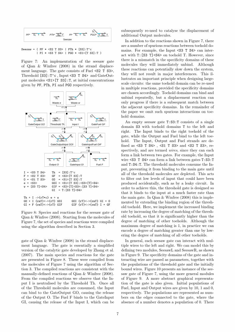
Figure 7 presents an implementation of the seesaw
6
Seesaw
TS3T
S1
S3 TTc
S3 PGO*PTh* PI*T S3PF* S2 S4
Seesaw = ( PF * <S2 T S3> | PTh * [S3]:T^c| PI * <S3 T S4> | PGO * <S1>[T S3]:T )
Figure 7: An implementation of the seesaw gateof Qian & Winfree (2008) in the strand displace-ment language. The gate consists of Fuel <S2 T S3>,Threshold [S3]:T^c , Input <S3 T S4> and GateOut-put molecules <S1>[T S3]:T, at initial concentrationsgiven by PF, PTh, PI and PGO respectively.
T
TS3T
S1
S3 T
S3T
S1 S4S3
TS3
S4
TT S3 T S3
TS3T
S2 S4S3
TS3T
S2
Tc
S3
S3
GateOutput GO Input I GateFuel GF
Output O GateInput GI Fuel F
TS3
S4
Waste w
GateOutputInput GOI GateInputFuel GIF
Threshold Th
Waste e
+T×c
+T
-T
+T
-T
+T
-T
+T
-T
S1 S2
S4
I = <S3 T S4> Th = [S3]:T^cF = <S2 T S3> GF = <S2>[T S3]:TO = <S1 T S3> GO = <S1>[T S3]:Te = <S3> GOI = <S1>[T S3]:<S3>[T]<S4>w = [S3 T]<S4> GIF = <S2>[T]<S3>:[S3 T]<S4>
GI = T:[S3 T]<S4>
Th + I ->{rT*c} e + wGO + I {rmT}<->{rT} GOI GOI {rT}<->{rmT} GI + OGI + F {rmT}<->{rT} GIF GIF {rT}<->{rmT} I + GF
Figure 8: Species and reactions for the seesaw gate ofQian & Winfree (2008). Starting from the molecules ofFigure 7, the set of species and reactions were compiledusing the algorithm described in Section 3.
gate of Qian & Winfree (2008) in the strand displace-ment language. The gate is essentially a simplifiedversion of the catalytic gate developed by Zhang et al.(2007). The main species and reactions for the gateare presented in Figure 8. These were compiled fromthe molecules of Figure 7 using the algorithm of Sec-tion 3. The compiled reactions are consistent with themanually-defined reactions of Qian & Winfree (2008).From the compiled reactions we observe that the In-put I is neutralised by the Threshold Th. Once allof the Threshold molecules are consumed, the Inputcan bind to the GateOutput GO, causing the releaseof the Output O. The Fuel F binds to the GateInputGI, causing the release of the Input I, which can be
subsequently re-used to catalyse the displacement ofadditional Output molecules.
In addition to the reactions shown in Figure 7, thereare a number of spurious reactions between toehold do-mains. For example, the Input <S3 T S4> can inter-act with T:[S3 T]<S4> on toehold T. However, sincethere is a mismatch in the specificity domains of thesemolecules they will immediately unbind. Althoughthese reactions can potentially slow down the system,they will not result in major interferences. This il-lustrates an important principle when designing large-scale circuits: the same toehold domain can be re-usedin multiple reactions, provided the specificity domainsare chosen accordingly. Toehold domains can bind andunbind repeatedly, but a displacement reaction canonly progress if there is a subsequent match betweenthe adjacent specificity domains. In the remainder ofthe paper we omit such spurious interactions on toe-hold domains.
An empty seesaw gate T:S3:T consists of a singledomain S3 with toehold domains T to the left andright. The Input binds to the right toehold of thegate, while the Output and Fuel bind to the left toe-hold. The Input, Output and Fuel strands are de-fined as <S3 T S4> , <S1 T S3> and <S2 T S3>, re-spectively, and are termed wires, since they can eachform a link between two gates. For example, the Inputwire <S3 T S4> can form a link between gates T:S3:Tand T:S4:T. The threshold molecules consume the In-put, preventing it from binding to the main gate untilall of the threshold molecules are depleted. This actsto filter out low levels of input that could have beenproduced accidentally, such as by a leaky circuit. Inorder to achieve this, the threshold gate is designed sothat it binds to the input at a much faster rate thanthe main gate. In Qian & Winfree (2008) this is imple-mented by extending the binding region of the thresh-old toehold. Here, we implement the increased bindingrate by increasing the degree of matching of the thresh-old toehold, so that it is significantly higher than thedegree of matching of other toeholds. Although themaximum degree of matching is 1, in practice we canencode a degree of matching greater than one by low-ering the degree of matching of all other toeholds.
In general, each seesaw gate can interact with mul-tiple wires to the left and right. We can model this bydefining two modules, SeesawL and SeesawR, as shownin Figure 9. The specificity domains of the gate and in-teracting wire are passed as parameters, together withthe populations of the threshold gate and the initiallybound wires. Figure 10 presents an instance of the see-saw gate of Figure 7, using the more general modulesof Figure 9. A more abstract graphical representa-tion of the gate is also given. Initial populations ofFuel, Input and Output wires are given by 10, 1 and 0,respectively. The populations are represented as num-bers on the edges connected to the gate, where theabsence of a number denotes a population of 0. There
7

SeesawL(S3,S1,PT,P)
TS3T
S1
Tc
S3 P*PT*
SeesawR(S3,S4,PT,P)
PT* Tc
S3 TS3
S4
TP*S3 T
Wire(S3,S4)
S4
Wire(S3,S4) = <S3 T S4>SeesawL(S3,S1,PT,P) = PT * T^c:[S3] | P * <S1>[T S3]:TSeesawR(S3,S4,PT,P) = PT * [S3]:T^c | P * T:[S3 T]<S4>
Figure 9: Generic modules for the seesaw gate of Fig-ure 7.
Input S4
Output S1
Fuel S2
10
Gate S3
-0.5
10
1
( SeesawL(S3,S1,0,10.0) | SeesawR(S3,S4,0.5,0)| 1*Wire(S3,S4) | 10*Wire(S2,S3) )
Figure 10: An instance of the seesaw gate of Figure 7,using the more general modules of Figure 9. A moreabstract graphical representation of the gate is alsogiven.
is also an initial population of 10 Output wires boundto the left side of the gate, assuming suitable popula-tion units. This is indicated by the number 10 insidethe left half of the circle, next to the Output wire.There are no Fuel or Input wires bound to the gate,since there are no positive numbers inside the circlenext to the Fuel or Input wires. The negative number-0.5 on the inside of the circle next to the Input wireindicates an initial population of 0.5 threshold gates.According to Qian & Winfree (2008), we assume thata given seesaw gate will not have both a population ofbound wires and a population of threshold gates. Un-der these assumptions, a single integer can be used torepresent both populations. If the integer is positivethen it represents the population of bound wires, andif it is negative then its absolute value represents thepopulation of threshold gates. For the program defini-tion of our seesaw modules, rather than using a singleinteger we use two positive numbers PT and P, withthe additional constraint that both numbers cannot begreater than zero simultaneously.
We can use these modules to implement the logicalOR gate presented in Qian &Winfree (2008), as shownin Figure 11. Gates with a dotted outline have a pop-ulation of zero, and are not needed. They are mainlyincluded to give a uniform representation. As a result,for the OR gate implementation only domains 3 and 4need to be passed as parameters. The OR gate takestwo wires that bind to the left of domain 3. Once oneor both of these wires are present in sufficient num-bers to consume all of the threshold gates, they willdisplace the wire <3 T 4> that is bound on the rightof domain 3. The fuel <3 T 5> ensures that the boundinput wires are freed again from the gate 3. A mod-ule for the AND gate can also be defined, though itsbehaviour is more complicated (see Qian & Winfree(2008) for full details). Here we have shown how see-
-.5
3
1.5
w13
w23
-.5 2.5
1
2
w34
4
5
w34 = w13 OR w23
OR(3,4) = new (1,2,5)( SeesawL(3,1,0.5,0) | SeesawL(3,2,0.5,0)| SeesawR(3,4,1.5,0)| 2.5*Wire(3,5) )
Figure 11: Example logical OR circuit made of seesawgates. Signal concentrations below 0.1x are consideredOFF, while signal concentrations above 0.9x are con-sidered ON.
saw gate modules can be used to construct simple logicgate modules, which can in turn be used to constructcomplex logical circuits of arbitrary size.
2.4 Case study: compiling chemical re-actions to DNA
The previous case studies described how physical DNAsystems can be represented as molecules in the stranddisplacement language. The molecules were then sys-tematically translated to chemical reactions for sim-ulation and analysis. This case study addresses thereverse question of how to translate an arbitrary setof chemical reactions to a set of DNA molecules, inorder to systematically derive a physical DNA imple-mentation. The question was previously addressed inSoloveichik et al. (2008) by translating a given set ofchemical reactions to an extended set of reactions rep-resenting the implemented system. Here we present atranslation from a set of chemical reactions directly toa set of DNA molecules. The extended set of reactionsfor these molecules is then derived automatically usingthe algorithm of Section 3.
We first illustrate the principle of the translationon a number of simple chemical reactions, using theapproach presented in Soloveichik et al. (2008). Es-sentially, each chemical species X is associated withthree distinct domains X1,X2,X3, where X1 and X3 aretoeholds. The general form of a species X is given by<H X1 X2 X3>, where <X1 X2 X3> denotes the recogni-tion region of the species, and <H> denotes the historyregion. We assume that members of the same speciesmust all have the same recognition region, but can havedifferent history regions.
Figure 12 presents a DNA implementation of adegradation reaction A r−→ ∅, where species A is asso-ciated with the recognition region <2 3 4>. The reac-tion is implemented by a population of gates g, whichtransform a strand <1 2 3 4> into inert waste. Thereaction rate r is obtained by using a constant popu-lation Pg of gates g, such that r = ρ2 · Pg. In order
8

1 432 2 3 4
Input A Gate g
2 3 4
1
Waste w
43
Empty e
+2
A = <1 2 3 4> g = 2:[3 4]e = <3 4> w = <1>[2 3 4]
A + g ->{r2} w + e
Figure 12: DNA implementation of a degradation re-action A r−→ ∅. The implementation uses a constantpopulation Pg of gates g such that r = ρ2 · Pg.
4
2
1 432 2 3 4
56
3 4
1
643 5
5 876
Input A Gate g
Waste wg Intermediate o
Waste wtOutput B
5 6
3
4 5 6
78
Gate t
+2
+4
A = <1 2 3 4> g = 2:[3 4]<5 6>o = <3 4 5 6> t = 4:[5 6]<7 8>B = <5 6 7 8> wt = <3>[4 5 6]
wg = <1>[2 3 4]
A + g ->{r2} wg + o o + t ->{r4} wt + B
Figure 13: DNA implementation of a transition reac-tion A
r−→ B. The implementation uses a constantpopulation Pg of gates g such that r = ρ2 · Pg, and avery large constant population Pt of translation gatest such that ρ4 · Pt� r.
to achieve this, Soloveichik et al. (2008) assume an ex-cess population of gates that is large enough to remaineffectively constant. We adopt the same approach forthe implementation of constant gate populations, butlater discuss a potential alternative.
Figure 13 presents a DNA implementation of a tran-sition reaction A r−→ B. As with degradation, the re-action is implemented by a constant population Pg ofgates g such that r = ρ2 · Pg. In order to ensure thatthe domains of species B are completely independentfrom the domains of species A, an additional transla-tion gate t is needed. Furthermore, in order to ensurethat the reaction remains effectively first order, a verylarge constant population Pt of translation gates t isused, such that ρ4 · Pt� r.
Figure 14 presents a DNA implementation of a pro-
4
1 432 2 3 4
56
9
109643 5 94 5 6
7
10
118 12
95 6 10
3
5 876 9 121110
Input A Gate g
Intermediate o Gate t
Waste wt Output B Output C
10
2 3 4
1
Waste wg
+2
+4
A = <1 2 3 4> g = 2:[3 4]<5 6 9 10>o = <3 4 5 6 9 10> t = 4:[5 6]<7 8>:[9 10]<11 12>B = <5 6 7 8> wt = <3>[4 5 6 9 10]C = <9 10 11 12> wg = <1>[2 3 4]
A + g ->{r2} wg + o o + t ->{r4} wt + B + C
Figure 14: DNA implementation of a production reac-tion A
r−→ B + C. The implementation is similar toFigure 13, except that the translation gate t producestwo output strands instead of one.
duction reaction Ar−→ B + C. The implementation
of the reaction is similar to Figure 13, except that theintermediate output strand o displaces two strands in-stead of one from the translation gate t, which corre-spond to the two output species of the reaction.
Figure 15 presents a DNA implementation of a bi-nary reaction A + B
r−→ C. The implementation isless straightforward than the previous examples, sincethe output C must only be produced when both inputsA and B are present. The solution, as presented inSoloveichik et al. (2008), is to use a linker gate l thatrapidly binds and unbinds the reactant B, such thatthe bound and free species B are in equilibrium, wheref(Bg) denotes the fraction of bound species B. Whenthe species A is present, it can interact with the boundform of species B to complete the reaction. The ratesand populations are chosen such that r = f(Bg) · ρ6.
Figure 16 presents a more general translation fromchemical reactions to DNA molecules, based on theapproach presented in Soloveichik et al. (2008). Thetranslation is defined for unary and binary reactions,but translations for higher-order reactions can be de-fined in a similar fashion. The translation is defined asa collection of modules in the strand displacement lan-guage, which take the populations of gates and buffersas parameters. The populations are chosen so as to ac-curately implement the corresponding reaction rates,using the approach outlined in the previous examples.The populations also take into account the fact that agiven species may be involved in multiple binary inter-actions simultaneously and can therefore bind to mul-tiple different gates, affecting the equilibrium of freeand bound species. As an alternative to varying the
9

2
-6
73 8
910
Gate Bg
5 876
Input A
6
41
63
Buffer b
+6
71 432 2 3 6 8
910
Input B Linker Gate l
+2
-2
2 73 8
910
Gate Bl
1
6
34
2
+6
73 8
Waste wl
7 10988 9 10
1112
Intermediate o
41
Gate t
5
6
+8
9 121110 9 10
Output C Waste wl
8
7
B = <1 2 3 4> l = 2:[3 6]:[7 8]<9 10>b = <3 6> Bl = <1>[2]<3 4>:[3 6]:[7 8]<9 10>A = <5 6 7 8> Bg = <1>[2 3]<4>:6:[7 8]<9 10>o = <7 8 9 10> t = 8:[9 10]<11 12>C = <9 10 11 12> wt = <7>[8 9 10]
wl = <1>[2 3]<4>:<5>[6 7 8]
B + l {rm2}<->{r2} Bl Bl {rm5}<->{r5} b + BgBg + A ->{r5} o + wg o + t ->{r8} C + wt
Figure 15: DNA implementation of a binary reactionA+B
r−→ C. The implementation uses large constantpopulations Pl and Pb of linker gates l and buffers b,respectively, such that Pl · ρ2 and Pb · ρ6 � r. Fur-thermore, the toehold unbinding rates are chosen suchthat ρ−2 and ρ−6 � r. These constraints ensure thatan equilibrium can be rapidly established between thepopulation of free linker gates l and bound linker gatesBg. The rates and populations are also chosen suchthat r = f(Bg) · ρ6, where f(Bg) denotes the fractionof bound species Bg at equilibrium. As with the unaryreactions, we use a very large constant population Ptof gates t such that ρ8 · Pt� r.
initial gate populations, we can also vary the degreeof complementarity of toeholds for each reaction, asdiscussed in Soloveichik et al. (2008).
As an example, we consider the coupled chemical re-actions for the chaotic system due to Willamowsky andRossle, which was used as a case study in Soloveichiket al. (2008). The reactions for this system are sum-marised in Table 1, together with their translation toDNA molecules. The translation is implemented usinga set of modules for unary and binary reactions, whichare defined in a similar fashion to the general mod-ules presented in Figure 16. The local domains used ineach of the modules ensure that the domains of differ-
X3X2X1
A1 A2 A3
I1X11
INXN1
INA3 I1
X12
X13
X11 XN1
XN2
XN3
INB3 I1
X12
X13
X11 XN1
XN2
XN3
B2A1 A2 B1 B3
unaryN( (A1, A2, A3), Pg, (X11, X12, X13), ... , (XN1, XN2, XN3) )
I1X11
INXN1
species(P,X1, X2, X3)
(I1,...,IN)
(I1,...,IN)
B1A2
Pg* Pt*
Pt*Pl* Pb*
binaryN( (A1, A2, A3), (B1, B2, B3), Pl, Pb, (X11, X12, X13), ... , (XN1, XN2, XN3) )
P*
species(P,X1,X2,X3) = P * <X1 X2 X3>
unaryN((A1,A2,A3),Pg,(X11,X12,X13),...,(XN1,XN2,XN3))=new (I1,...,IN)( Pg * A1:[A2 A3]<I1 X11 ... IN XN1>| Pt * A3:[I1 X11]<X12 X13>:...:[IN XN1]<XN2 XN3> )
binaryN((A1,A2,A3),(B1,B2,B3),Pl,Pb(X11,X12,X13),...,(XN1,XN2,XN3)) =
new (I1,...,IN)( Pl * A1:[A2 B1]:[B2 B3]<I1 X11 ... IN XN1>| Pb * <A2 B1>| Pt * B3:[I1 X11]<X12 X13>:...:[IN XN1]<XN2 XN3> )
Figure 16: Translation from chemistry to DNA, basedon the approach presented in Soloveichik et al. (2008).The translation is defined as a collection of modules inthe strand displacement language, where each chem-ical species X is associated with three distinct do-mains (X1,X2,X3). The species module implementsan initial population P of the species represented bydomains (X1,X2,X3). The unaryN and binaryN mod-ules implement unary and binary reactions of the formA
ri−→ X1 + . . .+XN and A+B ri−→ X1 + . . .+XN , re-spectively. The modules rely on a set of local domains(I1,...,IN) to limit interference between reactions.We assume that populations Pg, Pl, Pb and Pt arelarge enough to remain effectively constant, and thatPt is large enough to implement reactions that are ef-fectively immediate. The populations Pg, Pl, Pb arepassed as parameters to the modules, and are chosen toaccurately implement the corresponding reaction ratesas follows. We let f(X) denote the fraction of unboundspecies X and let f(Xg) denote the fraction of speciesX bound to a gate g. These populations can be com-puted beforehand, assuming that an equilibrium be-tween free and bound species is quickly reached. Inthe unary case, r = ρA1 · Pg · f(A) and ρA3 · Pt � r.In the binary case, r = ρB1 · f(B) · f(Ag) and ρB3 ·Pt,ρA1 · Pl, ρB1 · Pb, ρ−B1 , ρ−A1 � r . The latter con-straints ensure that all intermediate reactions are fastenough with respect to r that they can be effectivelyignored.
ent gates do not interfere with each other. Expandedversions of these modules are shown in Figure 17. The
10

A1 A2 A3
I1A1
J1
A1
A3 I1
A2
A3
A1
A ¾®r1
A + A
J1
A2
A3
A1
A2 A3
I2A1
A3 I2
A2
A3
A1A1 A2 A1
A+A ¾®r2
A
A2 A3B1 B2 A1
B+A ¾®r3
B + B
I3B1
J3
B1
A3 I3
B2
B3
B1 J3
B2
B3
B1
C1 C2 C3
I1C1
J1
C1
C3 I1
C2
C3
C1
C ¾®r6
C + C
J1
C2
C3
C1
C2 C3
I2C1
C3 I2
C2
C3
C1C1 C2 C1
C+C ¾®r7
C
C2 C3A1 A2 C1
A+C ¾®r4
B1 B2 B3
B ¾®r4
Gate g1 Gate t1
Linker Gate l2 Gate t2
Linker Gate l3 Gate t3
Linker Gate l5Gate g4
Linker Gate l7 Gate t7
Gate g6 Gate t6
Pg1 * Pt *
A1A2
Buffer b2
Pl2 * Pt * Pb2 *
Pl7 * Pt * C1C2
Buffer b7
Pb7 *
Pt *Pg6 *
Pl3 * A1B2
Buffer b3
Pb3 *
C1A2
Buffer b5
Pb5 *
Pt *
Pg4 * Pl5 *
Figure 17: DNA molecules obtained by expanding themodules of Table 1.
1
{A+ g1
A1−→ o1
o1 + t1 −→ A+A
2
A+ l2
A1−A1
Al2−A1A1
Ag2 + b2
A+Ag2A1−→ o2
o2 + t2 −→ A
3
B + l3
B1−B1
Bl3−A1A1
Bg3 + b3
A+Bg3A1−→ o3
o3 + t3 −→ B +B
4{B + g4
B1−→
5
A+ l5A1−A1
Al5−C1C1
Ag5 + b5
C +Ag5C1−→
6
{C + g6
C1−→ o6
o6 + t6 −→ C + C
7
C + l7
C1−C1
Cl7−C1C1
Cg7 + b7
C + Cg7C1−→ o7
o7 + t7 −→ C
Figure 18: Main species and reactions for the DNAmolecules of Figure 17. The reactions were compiledusing the algorithm of Section 3.
Table 1: DNA implementation of the chaotic chemicalsystem due to Willamowsky and Rossle, based on theimplementation of Soloveichik et al. (2008). The reac-tion rates are defined as r1 = 0.03, r2 = r7 = 5× 10⁴,r3 = r5 = 105, r4 = 0.01, r6 = 0.0165. The im-plementation uses modules unary0, unary2, binary0,binary1, and binary2, which are defined in a similarfashion to the general modules unaryN and binaryNpresented in Figure 16. The populations Pg1,...,Pl7,Pb2, Pb3, Pb, Pb7 and the toehold binding and unbind-ing rates are chosen to accurately implement the cor-responding reaction rates. The populations are passedas parameters to the modules, along with the speciesA, B, C, where A = (A1,A2,A3), B = (B1,B2,B3) andC = (C1,C2,C3).
# chemistry dna molecules1 A
r1−→ 2A unary2(A,Pg1,A,A)
2 2A r2−→ A binary1(A,A,Pl2,Pb2,A)
3 B +Ar3−→ 2B binary2(B,A,Pl3,Pb3,B,B)
4 Br4−→ unary0(B,Pg4)
5 A+ Cr5−→ binary0(A,C,Pl5,Pb5)
6 Cr6−→ 2C unary2(C,Pg6,C,C)
7 2C r7−→ C binary1(C,C,Pl7,Pb7,C) )
expansion is performed automatically by the compiler,as described in Section 3.
The main species and reactions generated from theDNA molecules are presented in Figure 18. The reac-tions are similar to those presented in Soloveichik et al.(2008), except that there are two reversible reactionsinstead of one for establishing an equilibrium betweenspecies, linker gates, and buffer strands. The addi-tional reactions will not affect the overall dynamics ofthe system, provided they are effectively immediate.According to Figure 18, this will require the toeholdunbinding rates involved in all of the equilibrium re-actions to be sufficiently rapid. In addition to the re-actions represented in Figure 18, a number of otherreactions are generated, which arise from the fact thatthe toeholds of some of the intermediate outputs canbind to multiple gates. For example, toehold A3 of theintermediate output <A2 A3 I1 A1 J1 A1> can bindto three distinct gates, even though it can only dis-place strands from one of these gates. This should notsignificantly affect the overall dynamics, provided thetoehold unbinding rates are also fast. Nevertheless, itis important to take into account these factors whendetermining toehold rates and gate populations.
As mentioned previously, the translations assumethat reaction gates are present in sufficiently largenumbers so as to remain effectively constant over time.Another way of ensuring constant gate populations isto introduce a reservoir of inactive gates that becomeactive each time a gate is used. An example design
11

294 5 6
7
10
118
Gate t
2 3 4
56
9
Gate g
10
3 4
56
910
10 11
Reserve r
Pg* Pt* Z*
Quencher q
211Z*
t = 4:[5 6]<7 8>:[9 10]<11> g = 2:[3 4]<5 6 9 10>r = 10:[11 2]:[3 4]<5 6 9 10> q = [11]:2(Pg*g | Pt*t | Z*r | Z*q)
Figure 19: A possible implementation of a replenish-able gate. The gates g and t implement a reaction ofthe form A
r−→ B. The extra reserve r is in excess, sothat whenever a reaction is executed, a new gate withthe same function as g is activated to take the place ofthe gate that was used.
is presented in Figure 19. The advantage of this de-sign is that we have a more precise control over thegate populations, and can use lower population num-bers. If needed, we can continually supply new inactivegates to ensure that the active gate population is keptconstant indefinitely.
Another issue that needs to be addressed is thefact that buffer strands continually accumulate aftereach execution of a bimolecular reaction. It shouldbe possible to engineer a more sophisticated collectionof molecules that also recycles excess buffer strandsfrom the system, so that the population of bufferstrands is kept constant. Finally, in many cases com-plete sequence independence between strands may notbe necessary, allowing various optimisations to be in-troduced, as discussed in Soloveichik et al. (2008).The use of a concise strand displacement languagefor describing the interactions between DNA moleculesshould facilitate the design and analysis of such opti-misations.
3 Methods
In this section we formalise the DNA strand displace-ment language as a process calculus. We give defi-nitions for the syntax and execution rules of the cal-culus, together with its translation to chemical reac-tions. The definitions are given in the style of pro-cess calculi such as the pi-calculus (Milner, 1999; San-giorgi &Walker, 2001; Turner, 1996), with the additionof a stochastic reduction semantics along the lines ofPhillips & Cardelli (2007). The formal definitions areused as the basis for an implementation of the stranddisplacement language, and are also used to reasonabout basic language properties.
3.1 Syntax of the strand displacementcalculus
The syntax of the DNA strand displacement calculus(DSD) is defined in terms of molecules D, molecule seg-ments G and sequences S, L, R, as shown in Table 2. A
Table 2: Syntax of the DNA strand displacement cal-culus (DSD), defined in terms of molecules D, moleculesegments G and sequences S, L, R. The syntax assumesthat 0 < c ≤ 1 and that all toeholds in an upper strand<_ S _> have a degree of matching c = 1.
dsd syntax descriptionD () Empty molecule
<_ S _> Upper strand with sequencecomplementary to S
G Molecule segment GD1 | D2 Parallel composition of
molecules D1 and D2new N D Molecules D with local domain
NX(n) Instance of a module X with
parameters nG N^c Toehold domain N with degree
of matching c<L>[S]<R> Double strand [S] with left
and right overhangs <L>, <R>G1:G2 Concatenation of G1 and G2
S N Domain NN^c Toehold domain N with degree
of matching cS1 S2 Concatenation of S1 and S2
L _ Empty sequence_ S Left overhanging sequence S
R _ Empty sequenceS _ Right overhanging sequence S
Table 3: Syntax abbreviations for the strand displace-ment calculus.
syntax abbreviationS _ S_ S SN^1 N<_>[S]<R> [S]<R><L>[S]<_> <L>[S]new N1 ... new NK D new (N1,...,NK) DD | ... | D︸ ︷︷ ︸
K
K*D
molecule D can be an upper strand <_ S _> with a se-quence that is complementary to S. The upper strandis terminated by an empty sequence _ at both ends,to allow for potentially empty left and right overhangswhen an upper strand binds to a molecule. The up-per strand can also be abbreviated to <S> by omittingthe empty sequences. A sequence S is a concatenationof one or more domains N, where a domain is a name
12

or number that represents a specific DNA sequence.A toehold domain is represented as N^c, where c de-notes the degree of matching, such that 0 < c ≤ 1.Toehold sequences are assumed to be between 4 and10 nucleotides in length. Sequences L and R denotepotentially empty sequences that overhang to the leftand right of a bound upper strand, respectively. Asegment G can be a lower strand with a single toeholddomain N^c, or a double strand <L>[S]<R> consistingof an upper strand <L S R> bound to a lower strandS. The upper and lower strands are bound along thedouble-stranded region [S], with upper strands <L>and <R> overhanging to the left and right. A segmentG can also be a concatenation G1:G2 of two segmentsG1 and G2. Importantly, when two segments are con-catenated they are assumed to be joined along a con-tinuous lower strand. Thus, the syntax only allows asingle lower strand per molecule.
Multiple molecules D1,...,DK can be executed in par-allel, written D1|...|DK. A domain N can also be re-stricted to molecules D, written new N D. This repre-sents the fact that domain N is unique to moleculesD and does not occur in any other molecules. Fi-nally, a molecule can be an instance X(n) of a mod-ule X with parameters n. We assume the exis-tence of a fixed environment of module definitionsX1(m1)=D1,...,XK(mK)=DK. The definitions are as-sumed to be non-recursive, such that a module cannotinvoke itself, either directly or indirectly via anothermodule.
We define a number of syntactic abbreviationsfor the calculus, as summarised in Table 3. Weomit terminating empty sequences, where S _ and_ S are abbreviated to S, and we abbreviate a toe-hold N^1 with degree of matching 1 to N. We alsoomit empty overhanging strands, where <_>[S]<R>is abbreviated to [S]<R>, and <L>[S]<_> is ab-breviated to <L>[S]. We abbreviate successive re-strictions new N1...new NK D to a single restrictionnew (N1,...,NK) D. Finally, we abbreviate K identi-cal copies of a molecule D | ... | D︸ ︷︷ ︸
K
to K*D.
3.2 Semantics of the strand displace-ment calculus
We consider a reduction semantics that explicitly rep-resents toehold binding, toehold unbinding and stranddisplacement, as defined in Table 4. Each toehold N^cis assigned corresponding binding and unbinding ratesgiven by ρN and ρ−N , respectively. The rule D r−→ D’means that D can reduce to D’ with rate r. We writeDrr′D’ as an abbreviation for D r−→ D’ and D’ r′−→ D .
We also write D −→ D’ as an abbreviation for D ξ−→ D’,where ξ represents a rate that is significantly fasterthan any of the toehold unbinding rates.
Rules (RB) and (RU) model strand binding and
unbinding along a toehold. Analogous rules are alsoneeded to represent toehold binding and unbinding inabsence of G1, G2, or both (not shown). Rules (RDR)and (RDL) model a strand being displaced from amolecule to the right and left, respectively. Rule (RE)allows reduction up to re-ordering of molecules. There-ordering relation is defined in Table 5, where D ≡ D’means that D and D’ are equivalent up to mixing ofmolecules and branch migration. We also allow thefollowing approximation to be made: if D
ρN
ρ−N
D’ −→ D
then DρN−→ D’, since the reverse reaction at rate ρ−N
will have a negligible rate compared to the alternativeforward reaction at rate ξ.
As mentioned above, a notion of equivalence (≡) isdefined in Table 5 to allow for mixing and branch mi-gration of molecules. The relation is assumed to be re-flexive, symmetric and transitive. Essentially, the rulesstate that the order of parallel molecules is not impor-tant, since molecules are assumed to be well-mixed.In addition, since branch migration reactions happenvery quickly compared with binding and unbinding re-actions, molecules are considered to be equivalent up tobranch migration. Rule (ENP) ensures that a domainN that is local to molecules D1 is not used in any par-allel molecules D2. If there are any name clashes, thedomain N is renamed locally inside D1. The set fn(D)denotes the set of free domain names that are used bymolecules D, where new N D acts as a binder for nameN in D. Rule (ED) allows an instance of a module tobe replaced with its definition, where the parametersm are replaced with n in molecules D, written D{m:=n}.
One of the key assumptions of the language is thattwo single-stranded molecules can only interact witheach other via complementary toehold domains. Thisis enforced at a syntactic level, by ensuring that amolecule with a lower strand is either a single-strandedtoehold domain N^c or a double-stranded sequencewith left and right overhangs. Thus, in order to ensurethat single strands can only ever interact on toeholds,it is sufficient to show that the syntax of the languageis preserved by reduction. This property is capturedby Proposition 1.
Proposition 1. ∀D ∈ DSD if D r−→ D’ then D ∈ DSD.
Proof. By induction on the derivation of reduction, ac-cording to Table 4. By inspection of the reductionrules, we observe that none of the rules result in theliberation of a single-stranded, non-toehold region ofa lower strand. Since reduction is also defined up tostructurally equivalent molecules, we prove a similarproperty for the structural equivalence rules of Ta-ble 5.
3.3 Compiling DNA molecules to reac-tions
Given a collection of DNA molecules, we generate acorresponding set of reactions by repeated application
13
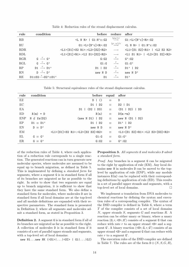
Table 4: Reduction rules of the strand displacement calculus.
rule condition before reduce after
RB <L N R> | G1:N^c:G2(ρN )·c−→ G1:<L>[N^c]<R>:G2
RU G1:<L>[N^c]<R>:G2(ρ−N )/c−→ <L N R> | G1:N^c:G2
RDR <L1>[S1]<S2 R1>:<L2>[S2]<R2> −→ <L1>[S1 S2]<R1> | <L2 S2 R2>RDL <L1>[S1]<R1>:<L2 S1>[S2]<R2> −→ <L1 S1 R1> | <L2>[S1 S2]<R2>RGR G r−→ G’ G:G2 r−→ G’:G2RGL G r−→ G’ G1:G r−→ G1:G’RP D1 r−→ D1’ D1 | D2 r−→ D1’ | D2RN D r−→ D’ new N D r−→ new N D’RE D1≡D2 r−→D2’≡D1’ D1 r−→ D1’
Table 5: Structural equivalence rules of the strand displacement calculus.
rule condition before equal afterEZ D | () ≡ DEC D1 | D2 ≡ D2 | D1EA D1 | (D2 | D3) ≡ (D1 | D2) | D3ED X(m) = D X(n) ≡ D{m:=n}ENP N /∈ fn(D2) (new N D1) | D2 ≡ new N (D1 | D2)EP D1 ≡ D1’ D1 | D2 ≡ D1’ | D2EN D ≡ D’ new N D ≡ new N D’EM <L1>[S1]<S2 R1>:<L2>[S2 S3]<R2> ≡ <L1>[S1 S2]<R1>:<L2 S2>[S3]<R2>EL G ≡ G’ G1:G ≡ G1:G’ER G ≡ G’ G:G2 ≡ G’:G2
of the reduction rules of Table 4, where each applica-tion of a reduction rule corresponds to a single reac-tion. The generated reactions can in turn generate newmolecular species, where molecules are assumed to beequal up to branch migration, as defined in Table 5.This is implemented by defining a standard form forsegments, where a segment G is in standard form if allof its branches are migrated as far as possible to theright. In order to show that two segments are equalup to branch migration, it is sufficient to show thatthey have the same standard form. We also define astandard form for molecules, where molecules D are instandard form if all local domains are at the top-leveland all module definitions are expanded with their re-spective parameters. The standard form is presentedin Definition 2, where all segments and molecules ad-mit a standard form, as stated in Proposition 3.
Definition 2. A segment G is in standard form if all ofits branches are migrated as far as possible to the right.A collection of molecules D is in standard form if itconsists of a set of parallel upper strands and segments,with a top-level set of local domains:new N1...new NK (<S1>|...|<SI> | G1|...|GJ)
Proposition 3. All segments G and molecules D admita standard form.
Proof. Any branches in a segment G can be migratedto the right by application of rule (EM). Any local do-mains new N in molecules D can be moved to the top-level by application of rule (ENP), while any moduleinstances X(n) can be replaced with their correspond-ing definitions by application of rule (ED). This resultsin a set of parallel upper strands and segments, with atop-level set of local domains.
We implement a translation from DNA molecules tochemical reactions by defining the syntax and execu-tion rules of a corresponding compiler. The syntax ofthe DSD compiler is defined in Table 6, where a termT of the compiler consists of a set of local domainsN , upper strands S, segments G and reactions R. Areaction can be either unary or binary, where a unaryreaction (G, r, <S>, G′) consists of a segment G that canreduce with rate r to an upper strand <S> and a seg-ment G’. A binary reaction (<S>, G, r, G′) consists of anupper strand <S> and a segment G that can reduce withrate r to a segment G’.
The execution rules of the DSD compiler are definedin Table 7. The rules are of the form D⊕ (N,S,G,R),
14
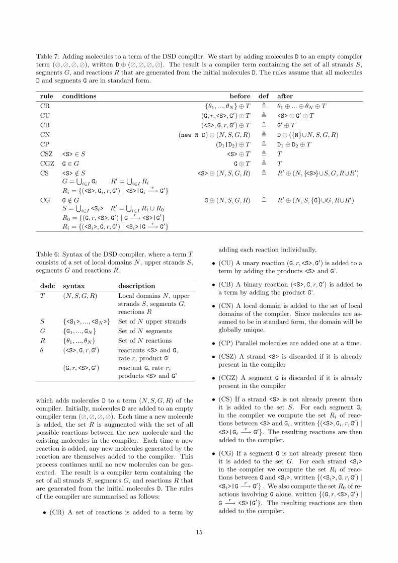
Table 7: Adding molecules to a term of the DSD compiler. We start by adding molecules D to an empty compilerterm (�,�,�,�), written D ⊕ (�,�,�,�). The result is a compiler term containing the set of all strands S,segments G, and reactions R that are generated from the initial molecules D. The rules assume that all moleculesD and segments G are in standard form.
rule conditions before def afterCR {θ1, ..., θN} ⊕ T , θ1 ⊕ ...⊕ θN ⊕ TCU (G, r, <S>, G′)⊕ T , <S>⊕ G′ ⊕ TCB (<S>, G, r, G′)⊕ T , G′ ⊕ TCN (new N D)⊕ (N,S,G,R) , D⊕ ({N}∪N,S,G,R)CP (D1|D2)⊕ T , D1 ⊕ D2 ⊕ TCSZ <S> ∈ S <S>⊕ T , T
CGZ G ∈ G G⊕ T , T
CS <S> /∈ SG =
⋃i∈I Gi R′ =
⋃i∈I Ri
Ri = {(<S>, Gi, r, G′) | <S>|Gir−→ G′}
<S>⊕ (N,S,G,R) , R′ ⊕ (N, {<S>}∪S,G,R∪R′)
CG G /∈ GS =
⋃i∈I <Si> R′ =
⋃i∈I Ri ∪R0
R0 = {(G, r, <S>, G′) | G r−→ <S>|G′}Ri = {(<Si>, G, r, G′) | <Si>|G
r−→ G′}
G⊕ (N,S,G,R) , R′ ⊕ (N,S, {G}∪G,R∪R′)
Table 6: Syntax of the DSD compiler, where a term Tconsists of a set of local domains N , upper strands S,segments G and reactions R.
dsdc syntax descriptionT (N,S,G,R) Local domains N , upper
strands S, segments G,reactions R
S {<S1>, ..., <SN>} Set of N upper strandsG {G1, ..., GN} Set of N segmentsR {θ1, ..., θN} Set of N reactionsθ (<S>, G, r, G′) reactants <S> and G,
rate r, product G’(G, r, <S>, G′) reactant G, rate r,
products <S> and G’
which adds molecules D to a term (N,S,G,R) of thecompiler. Initially, molecules D are added to an emptycompiler term (�,�,�,�). Each time a new moleculeis added, the set R is augmented with the set of allpossible reactions between the new molecule and theexisting molecules in the compiler. Each time a newreaction is added, any new molecules generated by thereaction are themselves added to the compiler. Thisprocess continues until no new molecules can be gen-erated. The result is a compiler term containing theset of all strands S, segments G, and reactions R thatare generated from the initial molecules D. The rulesof the compiler are summarised as follows:
• (CR) A set of reactions is added to a term by
adding each reaction individually.
• (CU) A unary reaction (G, r, <S>, G′) is added to aterm by adding the products <S> and G’.
• (CB) A binary reaction (<S>, G, r, G′) is added toa term by adding the product G’.
• (CN) A local domain is added to the set of localdomains of the compiler. Since molecules are as-sumed to be in standard form, the domain will beglobally unique.
• (CP) Parallel molecules are added one at a time.
• (CSZ) A strand <S> is discarded if it is alreadypresent in the compiler
• (CGZ) A segment G is discarded if it is alreadypresent in the compiler
• (CS) If a strand <S> is not already present thenit is added to the set S. For each segment Giin the compiler we compute the set Ri of reac-tions between <S> and Gi, written {(<S>, Gi, r, G′) |<S>|Gi
r−→ G′}. The resulting reactions are thenadded to the compiler.
• (CG) If a segment G is not already present thenit is added to the set G. For each strand <Si>in the compiler we compute the set Ri of reac-tions between G and <Si>, written {(<Si>, G, r, G′) |<Si>|G
r−→ G′} . We also compute the set R0 of re-actions involving G alone, written {(G, r, <S>, G′) |G r−→ <S>|G′}. The resulting reactions are thenadded to the compiler.
15

3.4 Compiling to DNA sequencesOne important issue that we have deliberately not ad-dressed is the automatic compilation of domains tonucleotide sequences. This is a challenging problemthat requires a detailed theoretical treatment, and istherefore beyond the scope of this paper. Instead,we propose to adopt the semi-automated approach de-scribed by Zhang et al. (2007). The approach uses se-quences composed of A,C,T and A,G,T for upper andlower strands, respectively, assuming Watson-Crickbase pairing between A,T and between G,C. As dis-cussed in Zhang et al. (2007), the restricted alpha-bet for upper and lower strands reduces potential sec-ondary structure, assuming that specificity domainson the lower strands are never exposed, as statedin Proposition 1. The approach first chooses ran-dom sequences composed of only A,C,T for the do-mains in the upper strands, and then constructs thecomplementary domains for the lower strands accord-ingly. Sub-sequences known to be problematic arealtered by hand, such as GGGG which causes to G-quadruplexing, or AAAAA which causes synthesis dif-ficulties. The remaining sequences are then concate-nated as appropriate to form DNA strands, which arefolded using the mFold web-server (Zuker, 2003) tocheck for the presence of undesired interactions. If nec-essary some of the domains in the upper strands arechanged by hand to G, and the corresponding domainsin the lower strands are updated accordingly.
For specificity domains, the sequences are longenough that they can be chosen to avoid interferencesbetween domains while also avoiding secondary struc-tures. For toehold domains, however, the number ofunique sequences is limited, since toeholds are only be-tween 4 and 10 nucleotides in length. As a result, acheck on the total number of distinct toeholds will needto be made before attempting to implement a givenDNA circuit. This can be achieved by converting thecircuit to standard form, according to Definition 2, andthen counting the total number of distinct toehold do-mains. Circuits where this number exceeds the givenlimit will not be implementable, which can be signaledby a compilation error.
As a rough estimate, we can use the results presentedin Marathe et al. (2001) to obtain approximate upperand lower bounds on the number of distinct toeholddomains. For example, if we assume that toehold do-mains are DNA sequences of length 10 that differ fromone another by at least 3 letters, then the number ofdistinct sequences that do not interfere with each otheron complementary strands, denoted by AR4 (10, 3), iscalculated to be between 1184 and 16912. Note thatfurther work is needed to reduce the gap between theupper and lower bounds, and the estimate does nottake into account the constraint that secondary struc-tures should be avoided, which further reduces thenumber of suitable sequences. Given that a single mis-match along a nucleotide sequence is sufficient to sig-
nificantly disrupt toehold binding, it may be sufficientfor toeholds to differ by only 2 letters, in which casethe number of distinct sequences AR4 (10, 2) is 131072.As with the previous calculation, this also includes se-quences that exhibit secondary structures, which willneed to be removed. Note also that there is a trade-offbetween the number of distinct toeholds and the extentto which the degree of matching matching of a giventoehold can be varied. A more drastic approach forreducing secondary structure of toeholds is to use se-quences composed of only A,C,T for upper strands, asdiscussed previously. For 3-letter sequences of length10 that differ by at least 2 letters, this gives a lowerbound of A3(10, 2) ≥ 2811.
In spite of these limitations, it is worth noting thatwe do not need a large number of distinct toeholds inorder to implement a large-scale DNA circuit. This isbecause the toehold is just a starting sequence for astrand displacement reaction: if the toehold binds butthe adjacent branch migration region does not, thenthe branch migration is going to bounce back at thesite of the first major disagreement, and the toeholdwill unbind. Although these reactions will potentiallyslow down the system, they will not result in majorinterferences. This allows the same toehold domainto be used in combination with a potentially unlim-ited number of specificity domains. Thus, a limit onthe number of distinct toeholds should not significantlylimit the size of a circuit. For example, if we considerthe gate motifs in Section 2.3 for designing large-scalelogic circuits, only a single toehold domain T was used.
4 DiscussionThis paper presented a programming language andcompiler for designing and simulating DNA circuits inwhich strand displacement is the main computationalmechanism. Starting from an initial set of molecules,the compiler computes the set of all possible reactionstogether with the set of all possible molecules that canbe produced. The generated reactions can then be sim-ulated using standard approaches, in order to evaluatethe circuit design. This greatly simplifies the designand testing of DNA circuits prior to their subsequentimplementation. The language was developed to takeinto account recent experimental and theoretical re-sults on the design of large-scale, efficient, modularDNA circuits. There are a number of areas for futurework, as outlined below.
The strand displacement language differs from tra-ditional imperative languages such as Pascal or C inthat the main primitives of the language are geared to-wards an implementation in physical DNA molecules.In particular, the language supports concurrent execu-tion of molecules by means of a parallel compositionprimitive, and parallel molecules can interact with eachother via specific toehold domains. Although the lan-guage also features more traditional primitives such as
16
parameterised modules and local variables, it is muchcloser to concurrent programming languages such asPhillips & Cardelli (2007) than to traditional impera-tive languages. Furthermore, instead of compiling theprogram to a sequence of binary digits for executionby a computer, programs will ultimately be compiledto sequences of letters A,C,G,T, that code for specificDNA molecules. For testing purposes, programs arecompiled to a set of chemical reactions by the compilerof Section 3, and the resulting reactions are simulatedusing standard tools.
In this paper we have presented the core primitivesof the strand displacement language, but additionalprogramming constructs can be added as straightfor-ward extensions. For example, conditionals can beused to check whether two domains are equal, andwhile loops can be used to iterate over a collectionof molecules. Arithmetic expressions can also be usedto express the initial populations of molecules. In allcases, the result of these computations will be a set ofDNA molecules, which will then be compiled to phys-ical DNA sequences or to a set of chemical reactionsfor simulation.
Developing a language that is tailor-made for mod-elling a particular class of DNA circuits has advantagesin terms of the clarity of the models and their closeresemblance to physical implementations. From a the-oretical perspective, however, it would also be interest-ing to investigate whether the strand displacement cal-culus can be encoded using more general calculi suchas kappa calculus (Danos et al., 2007) or stochasticpi-calculus (Priami, 1995; Phillips & Cardelli, 2007).Initial attempts suggest that such encodings are non-trivial and worthy of future investigation.
The design of the strand displacement language isstill in its early stages, and there are many ways inwhich the language can be extended, such as allowingmolecules to contain multiple lower strands. There isalso scope for defining additional syntactic constraintson molecules, in order to limit interference betweenmolecular domains. Another issue that we have de-liberately avoided relates to secondary structures inDNAmolecules. We have already mentioned how DNAsequences can be selected in order to eliminate suchstructures, but in future we may wish to include sim-ple features such as hairpin motifs, as used by Yin et al.(2008).
Rather than translating DNA molecules to chemicalreactions and then simulating the reactions in a sepa-rate tool, we can use our definition of reduction to im-plement a simulator that executes the DNA moleculesdirectly. This will allow us to manually progressthrough the simulation step by step, observing howthe molecules interact with each other and changetheir configurations over time. Such tools would beuseful for debugging the design of a particular set ofDNA molecules, since we can directly observe how themolecule changes configuration as a result of a partic-
ular interaction, and then intervene during the debug-ging cycle to try new molecular designs.
The last case study illustrated how we can translatea set of chemical reactions to DNA molecules. Each re-action was translated to populations of gate moleculesthat needed to remain constant over time, which re-quired excess molecules and pre-computation of equi-librium conditions. Rather than translating chemicalreactions to DNA, it would be interesting to define analternative high-level language that still retains an ex-plicit notion of a DNA molecule as a finite resource,while abstracting away from individual domains in theDNA sequence. An example of such a language is de-scribed by Cardelli (2009), as a means of simplifyingthe circuit design process.
As a proof of concept, we have implemented a pro-totype compiler for the DNA strand displacement lan-guage, which will be made available at (Phillips, 2009).Essentially, the tool can be used to program a collec-tion of DNA molecules and to check whether they con-form to the syntax of the language. If not, an error israised. Otherwise, a text file is produced containingthe full set of molecules and reactions that are gen-erated from the initial set of molecules. The gener-ated reactions can then be simulated using standardtechniques. In the longer term we hope to extendour language to further automate the process of de-signing DNA circuits, by including a compilation stepthat translates toehold and specificity domains to nu-cleotide sequences. In this case the translation wouldrely on a set of precomputed sequences that are suffi-ciently distinct from each other and that do not exhibitsecondary structures, using appropriate DNA codingof the regions (Kari et al., 2005; Zhang et al., 2007).The ultimate goal as described by Yin et al. (2008)is to be able to design and simulate arbitrarily com-plex DNA circuits on a computer, and automaticallycompile these to a corresponding set of nucleotide se-quences, ready for synthesis.
References
Adleman, L. M. (1994). Molecular computation ofsolutions to combinatorial problem. Science, 226,1021–1024.
Amos, M. (2005). Theoretical and Experimental DNAComputation. Springer.
Benenson, Y., Adar, R., Paz-Elizur, T., Livneh, Z., &Shapiro, E. (2003). DNA molecule provides a com-puting machine with both data and fuel. PNAS,100(5), 2191–2196. doi:10.1073/pnas.0535624100.
Benenson, Y., Gil, B., Ben-Dor, U., Adar, R., &Shapiro, E. (2004). An autonomous molecular com-puter for logical control of gene expression. Nature,429, 423–429. doi:10.1038/nature02551.
17

Benenson, Y., Paz-Elizur, T., Adar, R., Keinan,E., Livneh, Z., & Shapiro, E. (2001). Pro-grammable and autonomous computingmachinemade of biomolecules. Nature, 414, 430–434.doi:10.1038/35106533.
Cardelli, L. (2009). Strand algebras for DNA com-puting. In The 15th International Meeting on DNAComputing.
Danos, V., Feret, J., Fontana, W., Harmer, R., &Krivine, J. (2007). Rule-based modelling of cellularsignalling. In International Conference on Concur-rency Theory, volume 4703 of LNCS (pp. 17–41).:Springer.
Green, C. & Tibbetts, C. (1981). Reassociation ratelimited displacement of DNA strands by branch mi-gration. Nucleic Acids Research, 9(8), 1905–1918.
Kari, L., Konstantinidis, S., & Sosik, P. (2005).On properties of bond-free dna languages.Theoretical Computer Science, 334, 131–159.doi:10.1016/j.tcs.2004.12.032.
Kari, L., Paun, G., Rozenberg, G., Salomaa, A., &Yu, S. (1998). DNA computing, sticker systems,and universality. Acta Informatica, 35(5), 401–420.doi:10.1007/s002360050125.
Marathe, A., Condon, A. E., & Corn, R. M.(2001). On combinatorial dna word design.Journal of Computational Biology, 8(3), 201–219.doi:10.1089/10665270152530818.
Milner, R. (1999). Communicating and Mobile Sys-tems: the π-Calculus. Cambridge University Press.
Paun, G. & Rozenberg, G. (1998). Sticker sys-tems. Theoretical Computer Science, 204, 183–203.doi:10.1016/S0304-3975(98)00039-5.
Paun, G., Rozenberg, G., & Salomaa, A. (1998). DNAComputing: New Computing Paradigms. Springer.
Phillips, A. (2009). The DNA stranddisplacement language and simulator.http://research.microsoft.com/dna.
Phillips, A. & Cardelli, L. (2007). Efficient, correctsimulation of biological processes in the stochas-tic pi-calculus. In Computational Methods in Sys-tems Biology, volume 4695 of LNCS (pp. 184–199).:Springer. doi:10.1007/978-3-540-75140-3_13.
Priami, C. (1995). Stochastic π-calculus. The Com-puter Journal, 38(6), 578–589. Proceedings ofPAPM’95.
Qian, L. & Winfree, E. (2008). A simple DNA gatemotif for synthesizing large-scale circuits. In The14th International Meeting on DNA Computing.
Sakamoto, K., Gouzu, H., Komiya, K., Kiga, D.,Yokoyama, S., Yokomori, T., & Hagiya, M.(2000). Molecular computation by DNA hair-pin formation. Science, 288(5469), 1223–1226.doi:10.1126/science.288.5469.1223.
Sangiorgi, D. & Walker, D. (2001). The π-calculus: aTheory of Mobile Processes. Cambridge UniversityPress.
Seelig, G., Soloveichik, D., Zhang, D. Y., &Winfree, E.(2006). Enzyme-free nucleic acid logic circuits. Sci-ence, 314, 1585–1588. doi:10.1126/science.1132493.
Soloveichik, D., Seelig, G., & Winfree, E. (2008). DNAas a universal substrate for chemical kinetics. In The14th International Meeting on DNA Computing.
Turner, D. N. (1996). The Polymorphic Pi-Calculus:Theory and Implementation. PhD thesis, EdinburghUniversity.
Venkataraman, S., Dirks, R. M., Rothemund, P.W. K., Winfree, E., & Pierce, N. A. (2007). An au-tonomous polymerization motor powered by DNAhybridization. Nature Nanotechnology, 2, 490–494.doi:10.1038/nnano.2007.225.
Yin, P., Choi, H. M. T., Calvert, C. R., &Pierce, N. A. (2008). Programming biomolecu-lar self-assembly pathways. Nature, 451, 318–322.doi:10.1038/nature06451.
Yurke, B. & Mills Jr, A. P. (2003). Using DNA topower nanostructures. Genetic Programming andEvolvable Machines, 4, 111–122.
Yurke, B., Turberfield, A. J., Mills Jr, A. P., Simmel,F. C., & Neumann, J. L. (2000). A DNA-fuelledmolecular machine made of DNA. Nature, 406, 605–608. doi:10.1038/35020524.
Zhang, D. Y., Turberfield, A. J., Yurke, B., & Winfree,E. (2007). Engineering entropy-driven reactions andnetworks catalyzed by DNA. Science, 318, 1121–1125.
Zuker, M. (2003). Mfold web server for nu-cleic acid folding and hybridization prediction.Nucleic Acids Research, 31(13), 3406–3415.doi:10.1093/nar/gkg595.
18