a proposed devs standard: model and simulator interfaces
TRANSCRIPT
1
A Proposed DEVS Standard:
Model and Simulator Interfaces, Simulator
Protocol
DRAFT 1.0
Xiaolin Hu
Dept of Computer Science
Georgia State University
Bernard P. Zeigler
ACIMS
January 2008
Contents
A Proposed DEVS Standard: .............................................................................................. 1
Model and Simulator Interfaces, Simulator Protocol ......................................................... 1
2
1 Introduction................................................................................................................. 3
1.1 Brief DEVS Review.......................................................................................... 4
1.2 Conceptual Architecture of the Standard............................................................ 5
1.3 Layered structure – brief introduction of each layer........................................... 6
1.4 DEVS Interfaces ................................................................................................. 7
1.5 DEVS Supporting Interfaces............................................................................... 8
1.6 Message-related Interfaces.................................................................................. 9
1.7 Ensemble Interfaces .......................................................................................... 11
2 DEVS Modeling Interfaces....................................................................................... 12
3 Simulation Protocol .................................................................................................. 19
3.1 DEVS and non-DEVS Simulation with the CoreSimulatorInterface ............... 20
3.2 DEVS-to-DEVS Simulation with the CoreSimulatorInterface......................... 23
3.3 Simulate an Atomic model in virtual-time ....................................................... 27
3.4 Simulation of a coupled model in virtual-time ................................................. 28
4 Future Development.................................................................................................. 31
5 References................................................................................................................. 31
3
1 Introduction
This document describes the Discrete Event System Specification (DEVS) standard
adopted by the DEVS Standard Working Group. The DEVS formalism has been applied
in numerous research and industry contexts and many DEVS versions have been
developed. They are implemented on various computer platforms with different program
languages. They also vary in modeling level, distribution level and simulation mode such
as real-time simulation and virtual-time-mode simulation. To standardize all these
implementations and facilitate future development, this document sets out standardized
descriptions for DEVS models, simulators, and their interaction. However, the current
version is limited in scope to specification of virtual-time simulation of non-hierarchical
coupled models.
The standard is derived from the architectural description for the GenDEVS [2]
package of interfaces and classes in Java that underlie the DEVSJAVA modeling and
simulation environment which provides the capability to build discrete event models and
to simulate these models. The GenDEVS description employs the object oriented features
of classes and interfaces provided by Java that implement the Parallel DEVS formalism.
The standard presented in this document employs the same features but interprets them in
a manner that is not limited to Java implementation. This works because particular
features of the Java language are either not employed, or if employed, then they are given
definitions that are independent of Java implementation. For example, we use the concept
of interface from Java but define it in a language neutral manner. In the process of
generalization, we have allowed the standard to deviate in some ways from the original
source. These concern changing of names and organization of the interfaces that preserve
the original behavior but may make it easier to understand. The end result is an abstract
generic standard to which the GenDEVS implementation could conform with a change in
names of some of its methods.
Besides allowing DEVS models implemented in different languages to be simulated
together (e.g., in a distributed environment), a major goal is to allow non-DEVS models
to participate in such simulations. This is reflected in a reinterpretation of the interface

4
specifications derived from the GenDevs implementation that may prove confusing to
those familiar with the original. In the latter, the term coreSimulatorInterface suggested
that any DEVS simulator (a “device” that can execute a DEVS models, such as
coordinator or atomicSimulator) should implement this coreSimulatorInterface. In the
new standard, this name “core” refers to “essential” in that as long as a processor
implements this interface, it can participate in a simulation driven by a DEVS coordinator.
This means that a simulator of a standalone atomic model (called an atomicSimulator)
need not satisfy the coreSimulatorInterface while a simulator of a model that is in a
coupled model must do so. Similarly a coordinator of a coupled model need not satisfy
the coreSimulatorInterface although compliance is required of a coordinator of a coupled
model that is a part of a larger hierarchical composition. Some illustrative examples will
demonstrate how simulation of DEVS with non-DEVS federations can be achieved using
the standards developed here.
1.1 Brief DEVS Review
To understand how the standard works, we need to know there are two classes of
DEVS models (Atomic model and Coupled model) and several types of DEVS
simulation modes, e.g., virtual-time mode and real-time mode. An Atomic model is a
basic component which has relatively simple functionality. It has input ports, output ports,
states and internal or external transition functions. A coupled model is composed by
multiple atomic models or coupled models that have been previously defined. By
coupling one model’s output port to another model’s input port, a message can flow from
one model to another model.
Corresponding to different simulation modes, the standard has virtual-time mode and
real-time mode simulators. In virtual-time mode simulation, the simulator interprets time
as logical time so the simulation can skip from one event time to the next without waiting
for the actual time interval to expire. However, in real-time simulation, time is
interpreted as wall clock time, so the real-time simulator will wait for the interval to its
next scheduled event to expire before handling the event.
5
From the above introduction, we can see that the standard will have multiple
simulation scenarios. For example, considering the combinations of model type and
simulation mode we have: simulating an atomic model in virtual-time mode, simulating
an atomic model in real-time mode, simulating a coupled model in virtual-time mode and
simulating a coupled model in real-time mode.
In addition to the model type/simulation mode combinations, the standard allows for
the use of different forms of distribution of model components, e.g., single processor vs.
multi-processor, and different implementation platforms, such as Windows vs Unix,
different programming languages, such as Java vs C++, and different networking and
middleware frameworks such as .Net vs Apache.
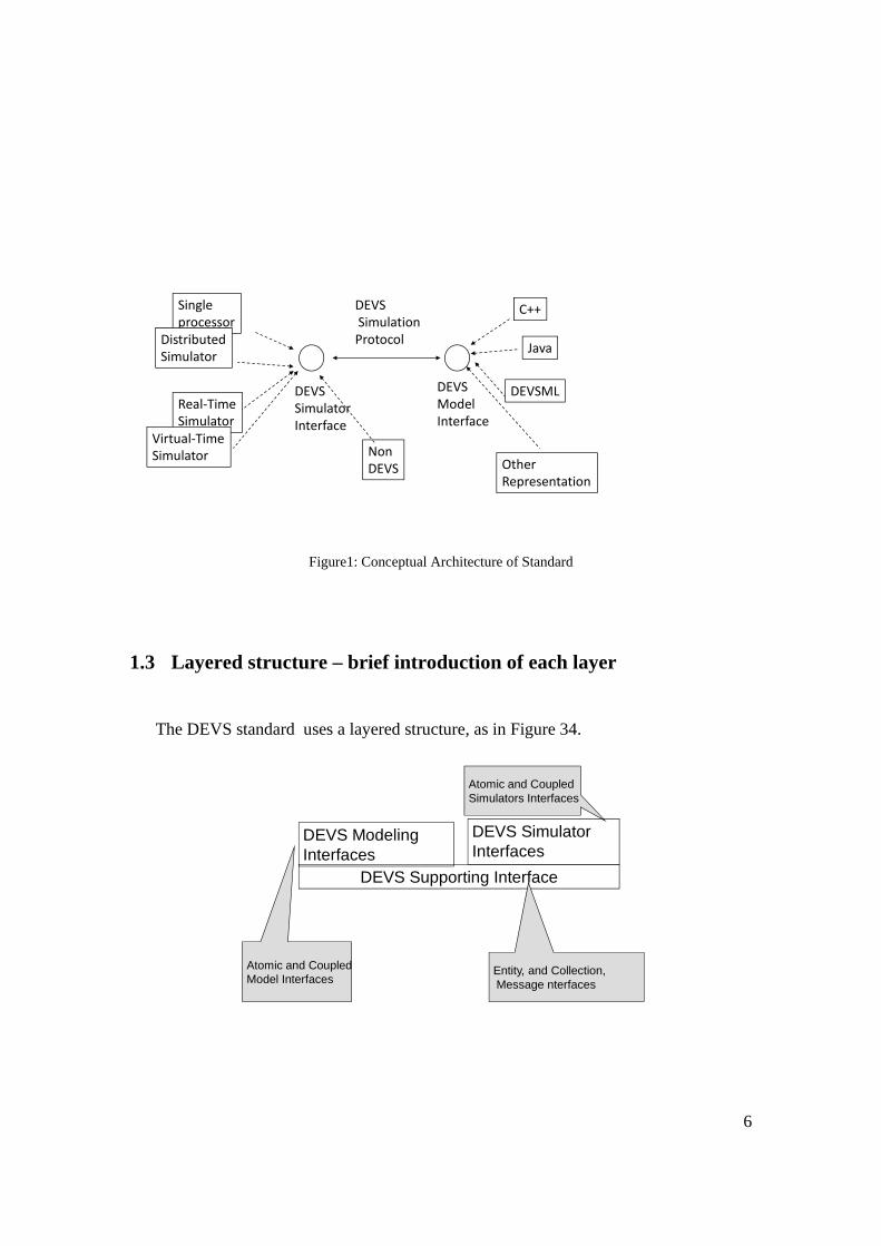
1.2 Conceptual Architecture of the Standard
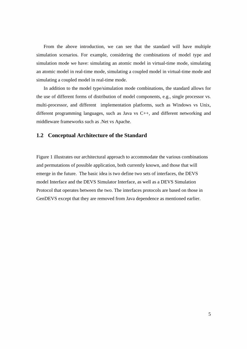
Figure 1 illustrates our architectural approach to accommodate the various combinations
and permutations of possible application, both currently known, and those that will
emerge in the future. The basic idea is two define two sets of interfaces, the DEVS
model Interface and the DEVS Simulator Interface, as well as a DEVS Simulation
Protocol that operates between the two. The interfaces protocols are based on those in
GenDEVS except that they are removed from Java dependence as mentioned earlier.
6
DEVSSimulatorInterface
Single processor
DistributedSimulator
Real‐TimeSimulator
C++
NonDEVS
DEVSModelInterface
Java
OtherRepresentation
DEVSSimulationProtocol
Virtual‐TimeSimulator
DEVSML
Figure1: Conceptual Architecture of Standard
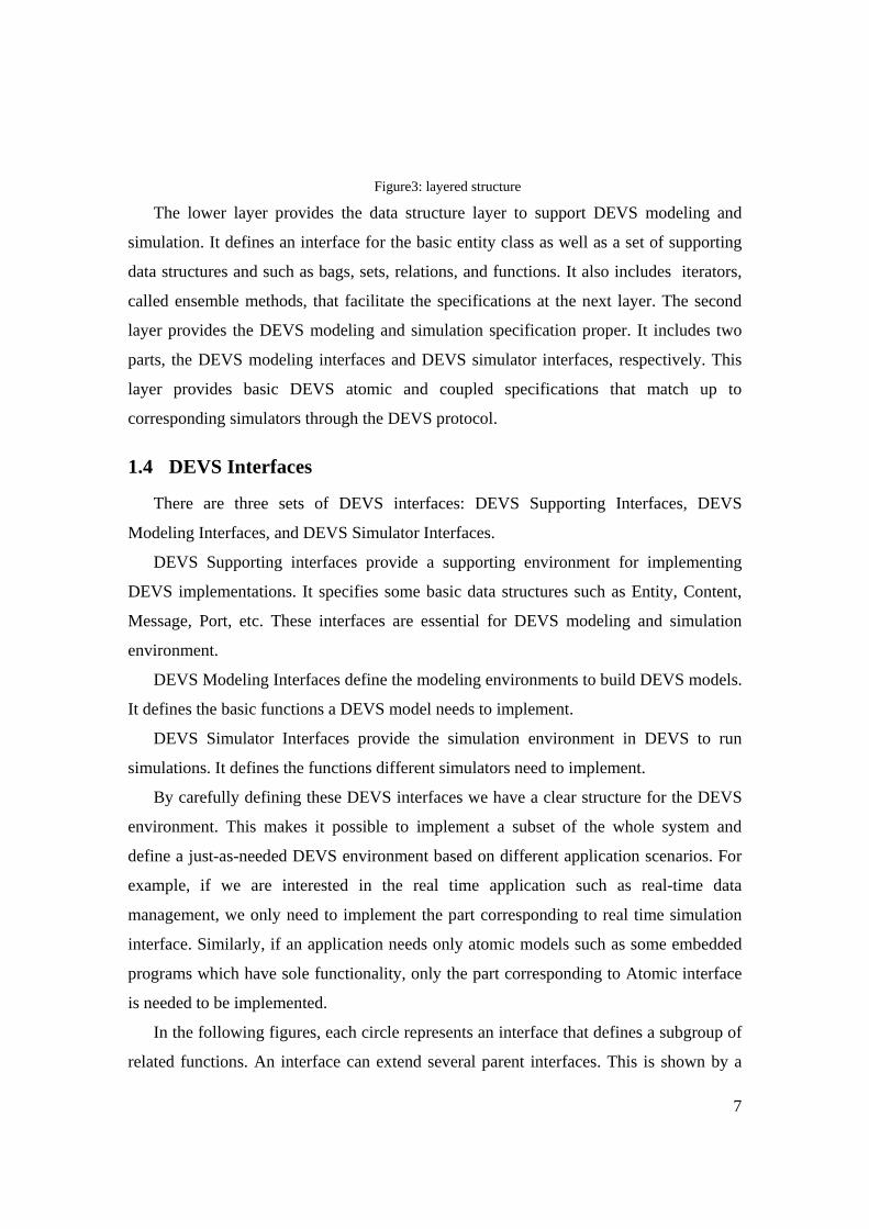
1.3 Layered structure – brief introduction of each layer
The DEVS standard uses a layered structure, as in Figure 34.
DEVS Modeling Interfaces
DEVS Supporting Interface
Entity, and Collection,Message nterfaces
Atomic and Coupled Model Interfaces
Atomic and Coupled Simulators Interfaces
DEVS Simulator Interfaces
7
Figure3: layered structure
The lower layer provides the data structure layer to support DEVS modeling and
simulation. It defines an interface for the basic entity class as well as a set of supporting
data structures and such as bags, sets, relations, and functions. It also includes iterators,
called ensemble methods, that facilitate the specifications at the next layer. The second
layer provides the DEVS modeling and simulation specification proper. It includes two
parts, the DEVS modeling interfaces and DEVS simulator interfaces, respectively. This
layer provides basic DEVS atomic and coupled specifications that match up to
corresponding simulators through the DEVS protocol.
1.4 DEVS Interfaces
There are three sets of DEVS interfaces: DEVS Supporting Interfaces, DEVS
Modeling Interfaces, and DEVS Simulator Interfaces.
DEVS Supporting interfaces provide a supporting environment for implementing
DEVS implementations. It specifies some basic data structures such as Entity, Content,
Message, Port, etc. These interfaces are essential for DEVS modeling and simulation
environment.
DEVS Modeling Interfaces define the modeling environments to build DEVS models.
It defines the basic functions a DEVS model needs to implement.
DEVS Simulator Interfaces provide the simulation environment in DEVS to run
simulations. It defines the functions different simulators need to implement.
By carefully defining these DEVS interfaces we have a clear structure for the DEVS
environment. This makes it possible to implement a subset of the whole system and
define a just-as-needed DEVS environment based on different application scenarios. For
example, if we are interested in the real time application such as real-time data
management, we only need to implement the part corresponding to real time simulation
interface. Similarly, if an application needs only atomic models such as some embedded
programs which have sole functionality, only the part corresponding to Atomic interface
is needed to be implemented.
In the following figures, each circle represents an interface that defines a subgroup of
related functions. An interface can extend several parent interfaces. This is shown by a
8
dotted line connecting the child and parent. An arrow will show the direction from parent
to child unless it is clear from the context. By extending several interfaces, a child
interface will inherit the attributes and functions from its parents. It can also add its own
functions and attributes so it will have its own personality.
1.5 DEVS Supporting Interfaces
DEVS supporting interfaces start with the EntityInterface for defining the entity, or base
object class, from which all classes will be derived. For example, this could be the Object
class in Java or the entity class in DEVSJAVA. We note this allows different
implementations to employ different classes to implement the EntityInterface while still
allowing such implementations to interoperate through the exposed functions defined by
it.
The Collection interface defines the basic functions of a collection of objects each of
which implements the EntityInterface. Consistent with the base object nature of
EntityInterface, Collection is derived from the latter. The behaviors of Collections and
ensembleCollections are uniquely specified using Object Behavior Specification in
Reference [ x].

9
interface EntityInterface{ String getName();boolean equalName(String name);}
interface Collection extends EntityInterface{ int size();void add(EntityInterface entity);void remove(EntityInterface entity);boolean contains(EntityInterface entity);}
EntityInterface Collection
0:n
Figure 4: DEVS Supporting Interfaces
interface EntityInterface{
String getName();
boolean equalName(String name);
}
interface Collection extends EntityInterface{
int size();
void add(EntityInterface entity);
void remove(EntityInterface entity);
boolean contains(EntityInterface entity);
}
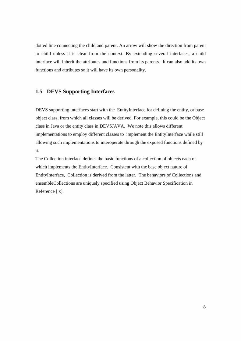
1.6 Message-related Interfaces
DEVS standard message concepts are briefly reviewed in Figure 5. DEVS models have
output ports through which messages are transmitted to input ports of receiving models
following routing that is specified by couplings.
10
DEVSModel
Output port
Input port
DEVSModel
message
coupling
Figure 5: DEVS Message concepts
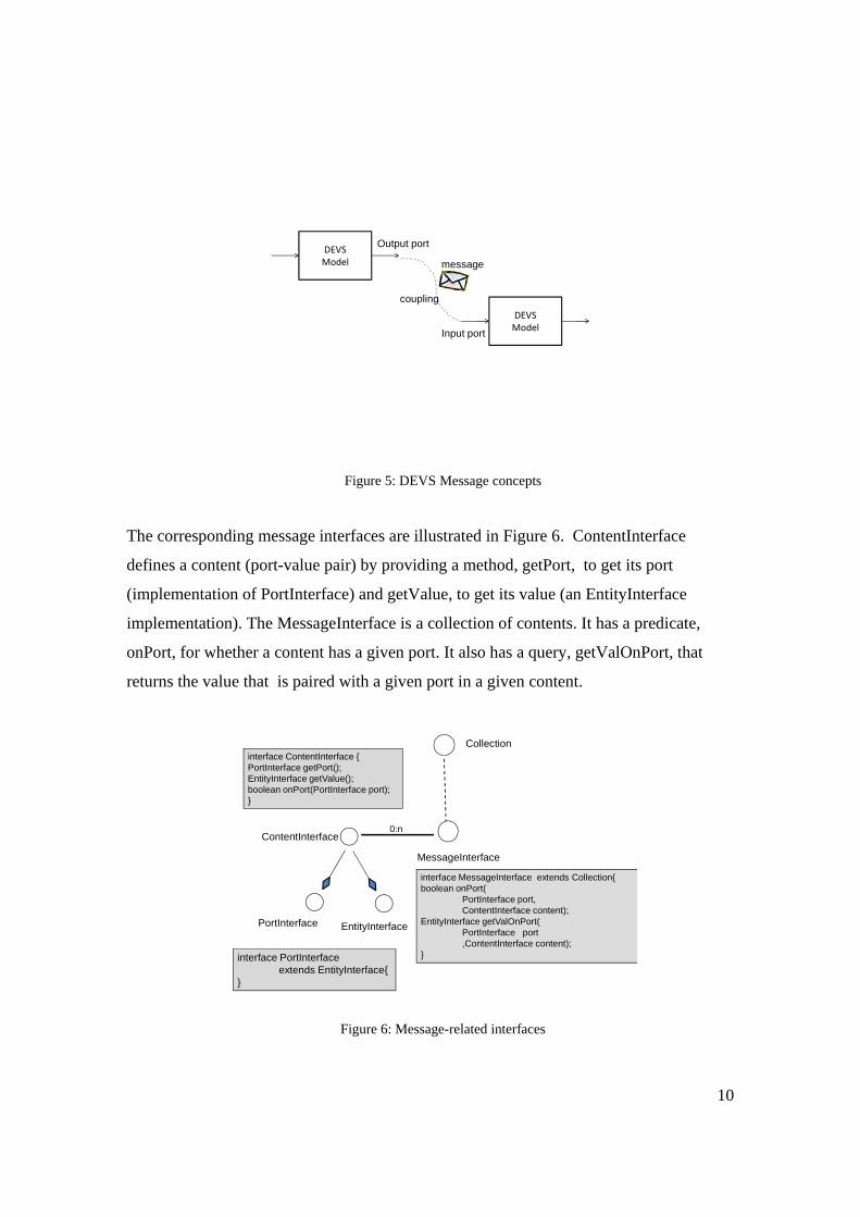
The corresponding message interfaces are illustrated in Figure 6. ContentInterface
defines a content (port-value pair) by providing a method, getPort, to get its port
(implementation of PortInterface) and getValue, to get its value (an EntityInterface
implementation). The MessageInterface is a collection of contents. It has a predicate,
onPort, for whether a content has a given port. It also has a query, getValOnPort, that
returns the value that is paired with a given port in a given content.
ContentInterface
MessageInterface
Collection
0:n
interface MessageInterface extends Collection{boolean onPort(
PortInterface port, ContentInterface content);
EntityInterface getValOnPort(PortInterface port,ContentInterface content);
}
PortInterface EntityInterface
interface ContentInterface {PortInterface getPort();EntityInterface getValue();boolean onPort(PortInterface port);}
interface PortInterfaceextends EntityInterface{
}
Figure 6: Message-related interfaces
11
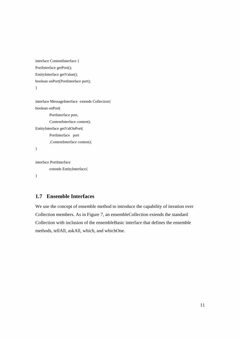
interface ContentInterface {
PortInterface getPort();
EntityInterface getValue();
boolean onPort(PortInterface port);
}
interface MessageInterface extends Collection{
boolean onPort(
PortInterface port,
ContentInterface content);
EntityInterface getValOnPort(
PortInterface port
,ContentInterface content);
}
interface PortInterface
extends EntityInterface{
}
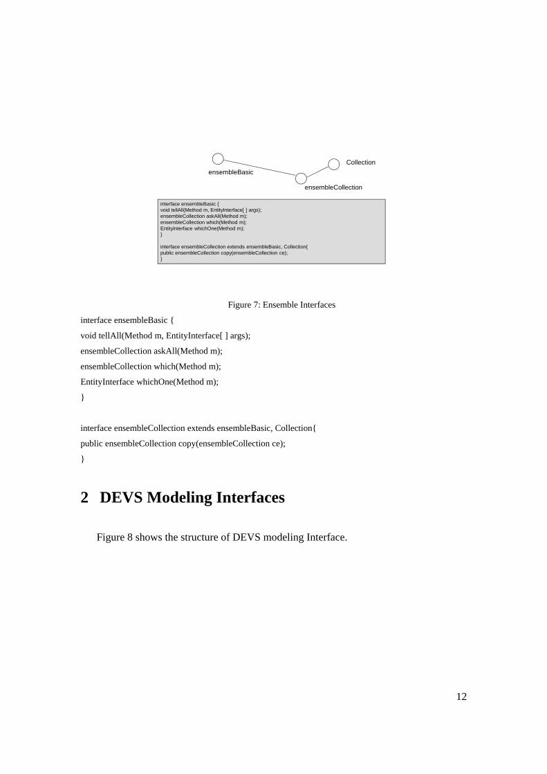
1.7 Ensemble Interfaces
We use the concept of ensemble method to introduce the capability of iteration over
Collection members. As in Figure 7, an ensembleCollection extends the standard
Collection with inclusion of the ensembleBasic interface that defines the ensemble
methods, tellAll, askAll, which, and whichOne.
12
ensembleBasicCollection
interface ensembleBasic {void tellAll(Method m, EntityInterface[ ] args); ensembleCollection askAll(Method m); ensembleCollection which(Method m); EntityInterface whichOne(Method m);}
interface ensembleCollection extends ensembleBasic, Collection{public ensembleCollection copy(ensembleCollection ce);}
ensembleCollection
Figure 7: Ensemble Interfaces
interface ensembleBasic {
void tellAll(Method m, EntityInterface[ ] args);
ensembleCollection askAll(Method m);
ensembleCollection which(Method m);
EntityInterface whichOne(Method m);
}
interface ensembleCollection extends ensembleBasic, Collection{
public ensembleCollection copy(ensembleCollection ce);
}
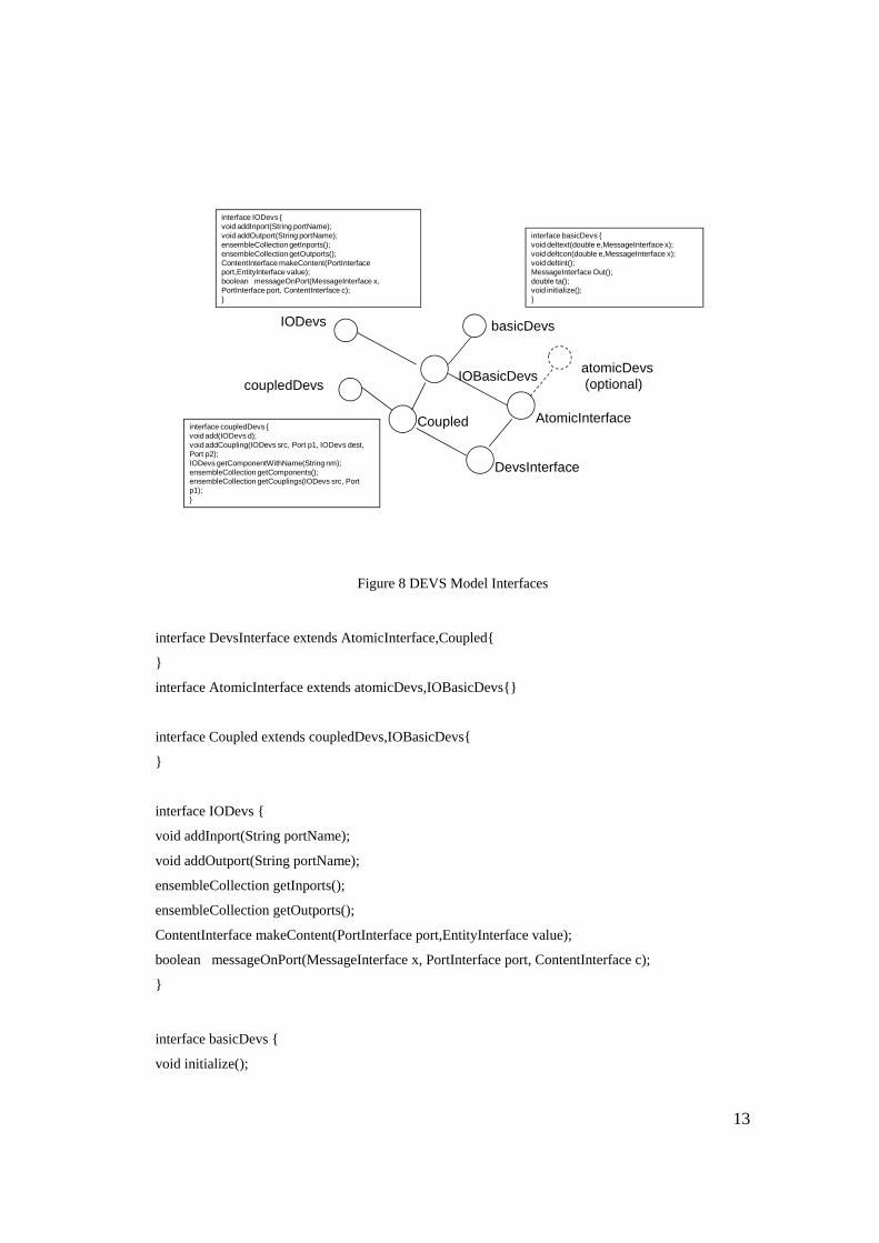
2 DEVS Modeling Interfaces
Figure 8 shows the structure of DEVS modeling Interface.
13
IODevs
atomicDevs(optional)
interface basicDevs {void deltext(double e,MessageInterface x);void deltcon(double e,MessageInterface x);void deltint();MessageInterface Out(); double ta();void initialize();}
IOBasicDevs
basicDevs
coupledDevs
AtomicInterfaceCoupledinterface coupledDevs {void add(IODevs d);void addCoupling(IODevs src, Port p1, IODevs dest, Port p2);IODevs getComponentWithName(String nm);ensembleCollection getComponents();ensembleCollection getCouplings(IODevs src, Port p1);}
DevsInterface
interface IODevs {void addInport(String portName);void addOutport(String portName);ensembleCollection getInports();ensembleCollection getOutports();ContentInterface makeContent(PortInterface port,EntityInterface value);boolean messageOnPort(MessageInterface x, PortInterface port, ContentInterface c);}
Figure 8 DEVS Model Interfaces
interface DevsInterface extends AtomicInterface,Coupled{
}
interface AtomicInterface extends atomicDevs,IOBasicDevs{}
interface Coupled extends coupledDevs,IOBasicDevs{
}
interface IODevs {
void addInport(String portName);
void addOutport(String portName);
ensembleCollection getInports();
ensembleCollection getOutports();
ContentInterface makeContent(PortInterface port,EntityInterface value);
boolean messageOnPort(MessageInterface x, PortInterface port, ContentInterface c);
}
interface basicDevs {
void initialize();
14
void deltext(double e,MessageInterface x);
void deltcon(double e,MessageInterface x);
void deltint();
MessageInterface Out();
double ta();
}
interface coupledDevs {
void add(IODevs d);
void addCoupling(IODevs src, PortInterface p1, IODevs dest, PortInterface p2);
String getComponentWithName(String nm);
ensembleCollection<String> getComponents();
ensembleCollection<String,Port> getCouplings(IODevs src, PortInterface p);
}
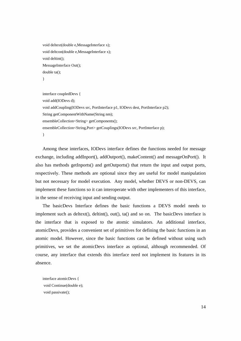
Among these interfaces, IODevs interface defines the functions needed for message
exchange, including addInport(), addOutport(), makeContent() and messageOnPort(). It
also has methods getInports() and getOutports() that return the input and output ports,
respectively. These methods are optional since they are useful for model manipulation
but not necessary for model execution. Any model, whether DEVS or non-DEVS, can
implement these functions so it can interoperate with other implementers of this interface,
in the sense of receiving input and sending output.
The basicDevs Interface defines the basic functions a DEVS model needs to
implement such as deltext(), deltint(), out(), ta() and so on. The basicDevs interface is
the interface that is exposed to the atomic simulators. An additional interface,
atomicDevs, provides a convenient set of primitives for defining the basic functions in an
atomic model. However, since the basic functions can be defined without using such
primitives, we set the atomicDevs interface as optional, although recommended. Of
course, any interface that extends this interface need not implement its features in its
absence.
interface atomicDevs {
void Continue(double e);
void passivate();
15
void passivateIn(String phase);
void holdIn(String phase, double time);
void holdIn(String phase, double time, Activity a);
boolean phaseIs(String phase);
}
The IOBasicDevs interface extends the String interface and basicDevs interface. It
provides a common basis for implementing atomic models and coupled models.
Combining IOBasicDevs with atomicDevs, we get AtomicInterface which defines the
functions an atomic model need to implement. Of course, if atomicDevs is omitted, then
AtomicInterface reduces to IOBasicDevs.
CoupledDevs interface defines the functions that are used in DEVS coupled models.
It has methods add() and addCoupling() that enable adding components and couplings to
the model. It also has optional methods getComponentWithName() and getComponents()
methods for retrieving a component by name and for accessing all components; and
getCouplings() to access the component/port pairs associated with a component and a
port.
Combining IOBasicDevs with CoupledDevs, we get Coupled which defines the
functions a coupled model needs to implement.
2.1 Extending the “Core” interfaces The above interfaces define the “core” of DEVS modeling. Later extensions of the
DEVS standard can be added based on these core interfaces. For example, to support
dynamic structure modeling, a dynamicStructure interface can be defined to be
implemented by an atomic model. interface dynamicStructureInterface {
void addCoupling(String srcName, String p1, String destName, String p2);
void removeCoupling(String srcName, String p1, String destName, String p2);
void addModel(String ModelName);
void removeModel(String ModelName);
void addInport(String ModelName, String port);
void addOutport(String ModelName, String port);
void removeInport(String ModelName, String port);
16
void removeOutport(String ModelName, String port);
}
Note that since changes to model structure are specified within a model, we use strings
rather than objects in the signatures. These strings must be used to find the objects
associated with these names.
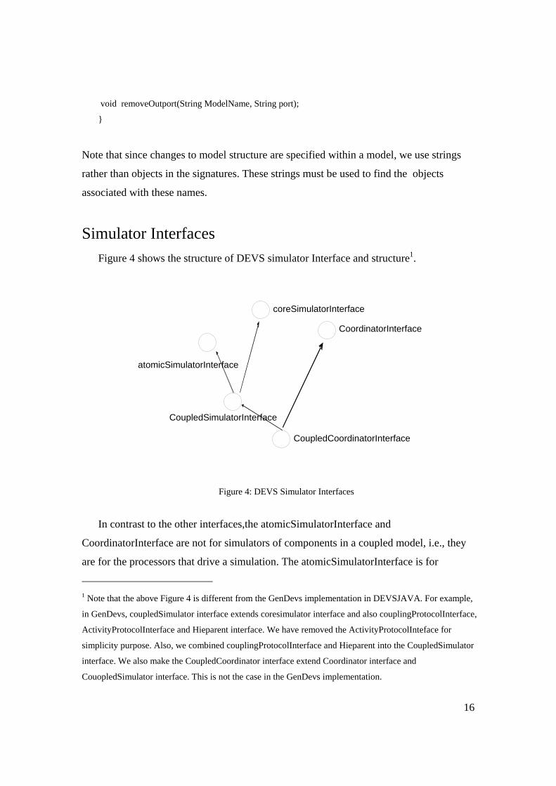
Simulator Interfaces Figure 4 shows the structure of DEVS simulator Interface and structure1.
Figure 4: DEVS Simulator Interfaces
In contrast to the other interfaces,the atomicSimulatorInterface and
CoordinatorInterface are not for simulators of components in a coupled model, i.e., they
are for the processors that drive a simulation. The atomicSimulatorInterface is for
1 Note that the above Figure 4 is different from the GenDevs implementation in DEVSJAVA. For example,
in GenDevs, coupledSimulator interface extends coresimulator interface and also couplingProtocolInterface,
ActivityProtocolInterface and Hieparent interface. We have removed the ActivityProtocolInteface for
simplicity purpose. Also, we combined couplingProtocolInterface and Hieparent into the CoupledSimulator
interface. We also make the CoupledCoordinator interface extend Coordinator interface and
CouopledSimulator interface. This is not the case in the GenDevs implementation.
coreSimulatorInterface
atomicSimulatorInterface
CoupledSimulatorInterface
CoordinatorInterface
CoupledCoordinatorInterface
17
simulating a single stand-alone DEVS atomic model. The CoordinatorInterface is for
simulating a coupled model. For some reason (probably because I am used to the GenDevs implementation), I feel the name of
coreSimulatorInterface is kind of confusing. This name suggests that any DEVS simulator (here I mean a
“device” that can execute a DEVS model, such as coordinator or atomicSimulator) should implement this
coreSimulatorInterface. This is different from what is shown in Figure 4. In Figure 4, it is actually a
componentSimulator interface (not the coordinator itself) that can work with a coordinator. In other words,
as long as a simulator implements this interface, it can participate in a simulation driven by a coordinator
(assuming such a coordinator exists). This brings out my second discussion. From Figure 1, it seems two of
the major goals of the standardization is to allow 1) a non-DEVS model to work with a DEVS model; 2)
models implemented in different languages can be simulated together (e.g., in a distributed environment). If
this is true, it will be very helpful to demonstrate how that can be achieved using the standards developed
here. Some illustrative examples may be developed (at the conceptual level). This might be part of the next
step (it will also help to test/refine the interfaces developed here).
The basic interface for DEVS and non-DEVS simulators is CoreSimulatorInterface.
interface coreSimulatorInterface{
void setSimulators(Collection<CoreSimulatorInterface>);
void initialize();
Double nextTN(); //Double is a class that wraps a double value
void computeInputOutput(Double t);
void applyDeltFunc(Double t);
void putContentOnSimulator(CoreSimulatorInterface sim, ContentInterface c);
void sendMessages();
}
// is setSimulators() implementation specific? i.e., it suggests a simulator know all other simulators.
Can we have a different implementation? OR should this be part of the standardization?
//BPZ: I think it should be in the standard although we don’t tie down the form in which the simulators
are expressed. This is because to do sendMessages federates have to know the other simulators.
The AtomicSimulatorInterface provides the methods needed for stand-alone
simulation of atomic DEVS models. Methods needed for simulation of atomic models as
components in coupled models are provided by the CoupledSimulatorInterface, which
extends the AtomicSimulatorInterface and the CoreSimulatorInterface. The
18
CoordinatorInterface provides the methods needed by a coordinator to simulate a coupled
model. To handle simulation of hierarchical coupled models, we note that a processor can
coordinate the processors below it as well as participate with peers in a coupled model
above it. To allow such downward and upward facing interfaces, the
CoupledCoordinatorInterface extends both the CoordinatorInterface and the
CoupledSimulatorInterface. This enables a processor satisfying the
CoupledCoordinatorInterface to participate both as a coordinator for its own coupled
model as well as providing a CoupledSimulatorInterface to the coordinator above it.
The following interfaces are for simulation of DEVS models that satisfy the DEVS
modeling interfaces as described above.
interface AtomicSimulatorInterface {
void initialize();
Double nextTN();
void computeInputOutput(Double t);
MessageInterface getOutput();
void applyDevsDeltfunc(Double t, MessageInterface x);
void simulate(int numIter);
void simInject(double e,MessageInterface m);
}
Note that applyDevsDeltfunc() employs DEVS model interfaces to compute the
atomic model transition function as illustrated in the next section.
interface CoupledSimulatorInterface extends AtomicSimulatorInterface,CoreSimulatorInterface{
CoupledSimulatorInterface getSimulatorOf(String ModelName);
void addPair(Pair cs,Pair cd); //add coupling pair
void removePair(Pair cs, Pair cd); //remove coupling pair
void setParent(CoordinatorInterface p);
CoordinatorInterface getParent();
}
19
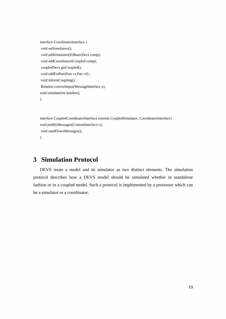
interface CoordinatorInterface {
void setSimulators();
void addSimulator(IOBasicDevs comp);
void addCoordinator(Coupled comp);
coupledDevs getCoupled();
void addExtPair(Pair cs,Pair cd) ;
void informCoupling();
Relation convertInput(MessageInterface x);
void simulate(int numIter);
}
interface CoupledCoordinatorInterface extends CoupledSimulator, CoordinatorInterface{
void putMyMessages(ContentInterface c);
void sendDownMessages();
}
3 Simulation Protocol DEVS treats a model and its simulator as two distinct elements. The simulation
protocol describes how a DEVS model should be simulated whether in standalone
fashion or in a coupled model. Such a protocol is implemented by a processor which can
be a simulator or a coordinator.
20
Coordinator
Atoimc1
Non-DEVS Simulator
Atoimc2
simulators.tellAll("initialize“)
simulators.AskAll(“nextTN”)
simulators.tellAll("computeInputOutput“)
simulators.tellAll("sendMessages")
simulators.tellAll("
Coordinator
DEVSModel
1
simulators.tellAll("initialize“)
simulators.AskAll(“nextTN”)
simulators.tellAll("computeInputOutput“)
simulators.tellAll("sendMessages")
simulators.tellAll("ApplyDeltFunc”)
putContentOnSimulatorDEVS Simulator
DEVS Simulator
DEVSModel
2
?
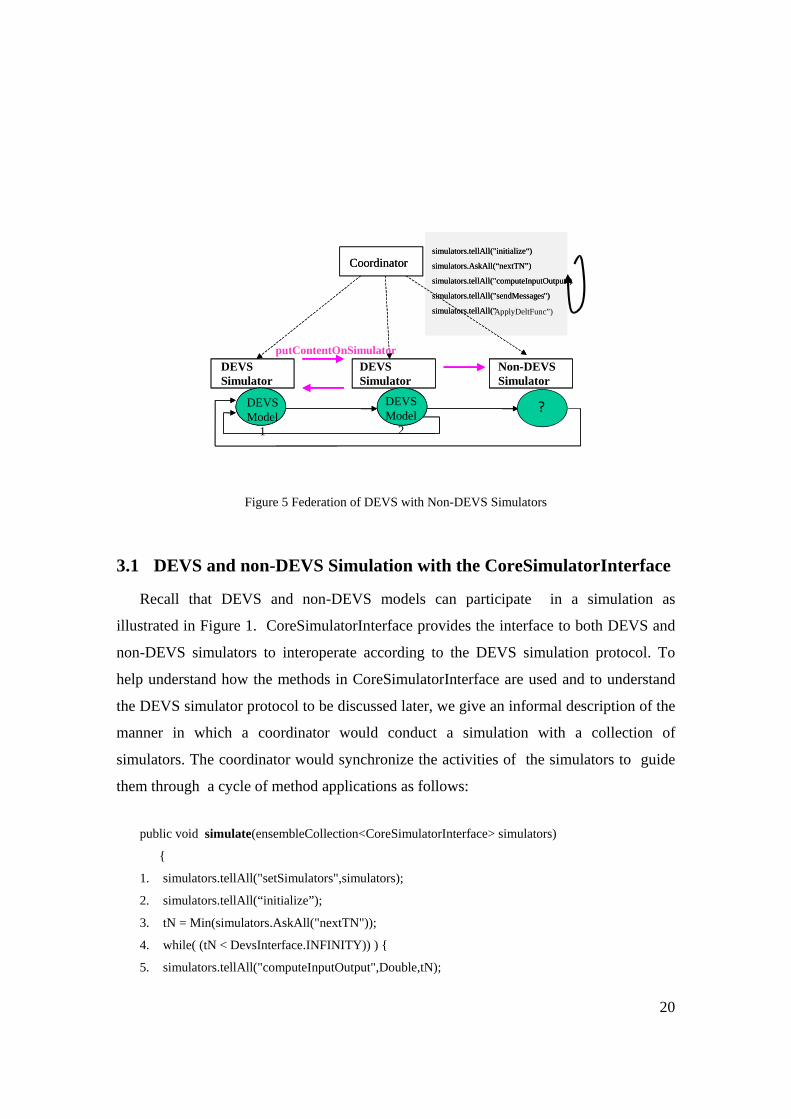
Figure 5 Federation of DEVS with Non-DEVS Simulators
3.1 DEVS and non-DEVS Simulation with the CoreSimulatorInterface
Recall that DEVS and non-DEVS models can participate in a simulation as
illustrated in Figure 1. CoreSimulatorInterface provides the interface to both DEVS and
non-DEVS simulators to interoperate according to the DEVS simulation protocol. To
help understand how the methods in CoreSimulatorInterface are used and to understand
the DEVS simulator protocol to be discussed later, we give an informal description of the
manner in which a coordinator would conduct a simulation with a collection of
simulators. The coordinator would synchronize the activities of the simulators to guide
them through a cycle of method applications as follows:
public void simulate(ensembleCollection<CoreSimulatorInterface> simulators)
{
1. simulators.tellAll("setSimulators",simulators);
2. simulators.tellAll(“initialize”);
3. tN = Min(simulators.AskAll("nextTN"));
4. while( (tN < DevsInterface.INFINITY)) ) {
5. simulators.tellAll("computeInputOutput",Double,tN);
21
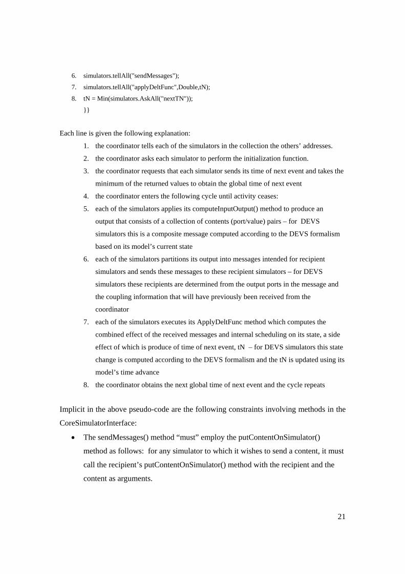
6. simulators.tellAll("sendMessages");
7. simulators.tellAll("applyDeltFunc",Double,tN);
8. tN = Min(simulators.AskAll("nextTN"));
}}
Each line is given the following explanation:
1. the coordinator tells each of the simulators in the collection the others’ addresses.
2. the coordinator asks each simulator to perform the initialization function.
3. the coordinator requests that each simulator sends its time of next event and takes the
minimum of the returned values to obtain the global time of next event
4. the coordinator enters the following cycle until activity ceases:
5. each of the simulators applies its computeInputOutput() method to produce an
output that consists of a collection of contents (port/value) pairs – for DEVS
simulators this is a composite message computed according to the DEVS formalism
based on its model’s current state
6. each of the simulators partitions its output into messages intended for recipient
simulators and sends these messages to these recipient simulators – for DEVS
simulators these recipients are determined from the output ports in the message and
the coupling information that will have previously been received from the
coordinator
7. each of the simulators executes its ApplyDeltFunc method which computes the
combined effect of the received messages and internal scheduling on its state, a side
effect of which is produce of time of next event, tN – for DEVS simulators this state
change is computed according to the DEVS formalism and the tN is updated using its
model’s time advance
8. the coordinator obtains the next global time of next event and the cycle repeats
Implicit in the above pseudo-code are the following constraints involving methods in the
CoreSimulatorInterface:
• The sendMessages() method “must” employ the putContentOnSimulator()
method as follows: for any simulator to which it wishes to send a content, it must
call the recipient’s putContentOnSimulator() method with the recipient and the
content as arguments.
22
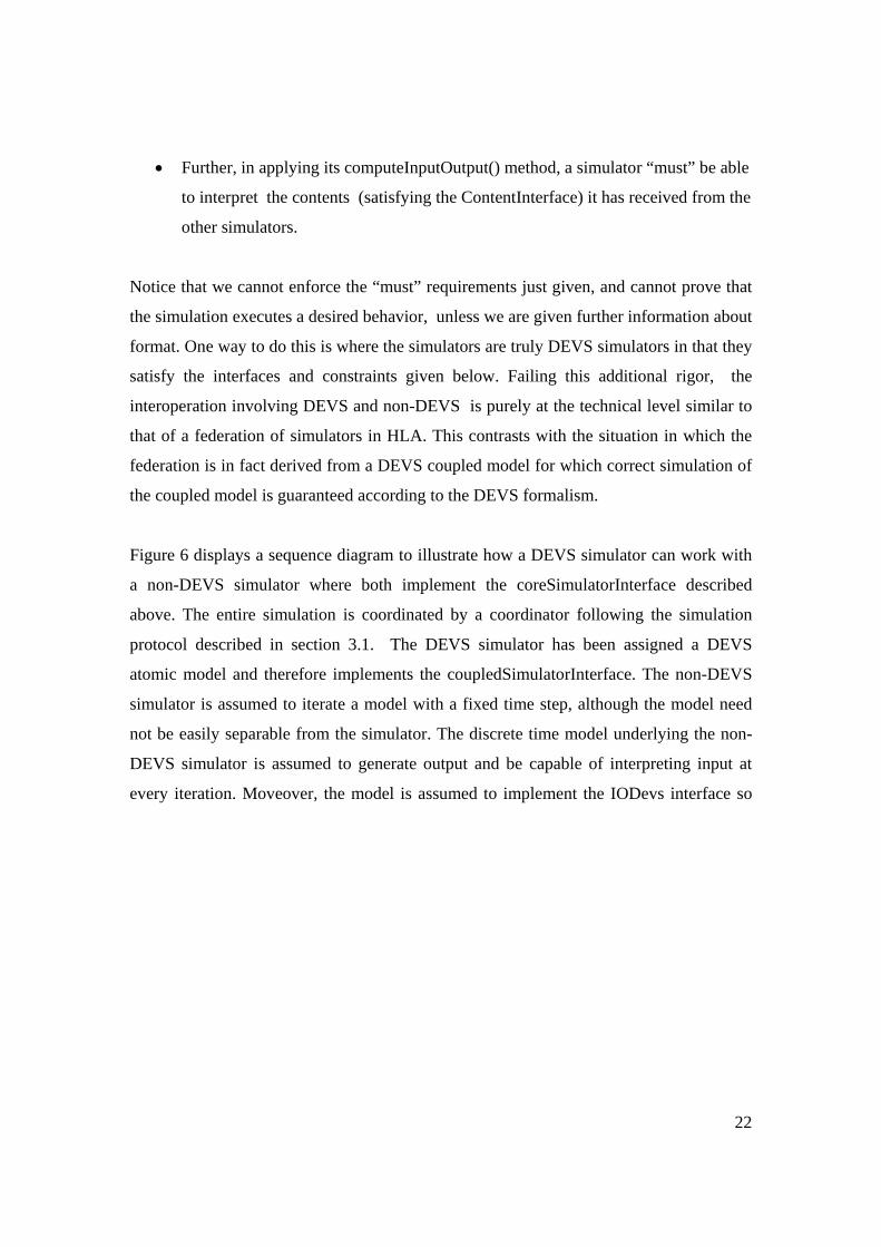
• Further, in applying its computeInputOutput() method, a simulator “must” be able
to interpret the contents (satisfying the ContentInterface) it has received from the
other simulators.
Notice that we cannot enforce the “must” requirements just given, and cannot prove that
the simulation executes a desired behavior, unless we are given further information about
format. One way to do this is where the simulators are truly DEVS simulators in that they
satisfy the interfaces and constraints given below. Failing this additional rigor, the
interoperation involving DEVS and non-DEVS is purely at the technical level similar to
that of a federation of simulators in HLA. This contrasts with the situation in which the
federation is in fact derived from a DEVS coupled model for which correct simulation of
the coupled model is guaranteed according to the DEVS formalism.
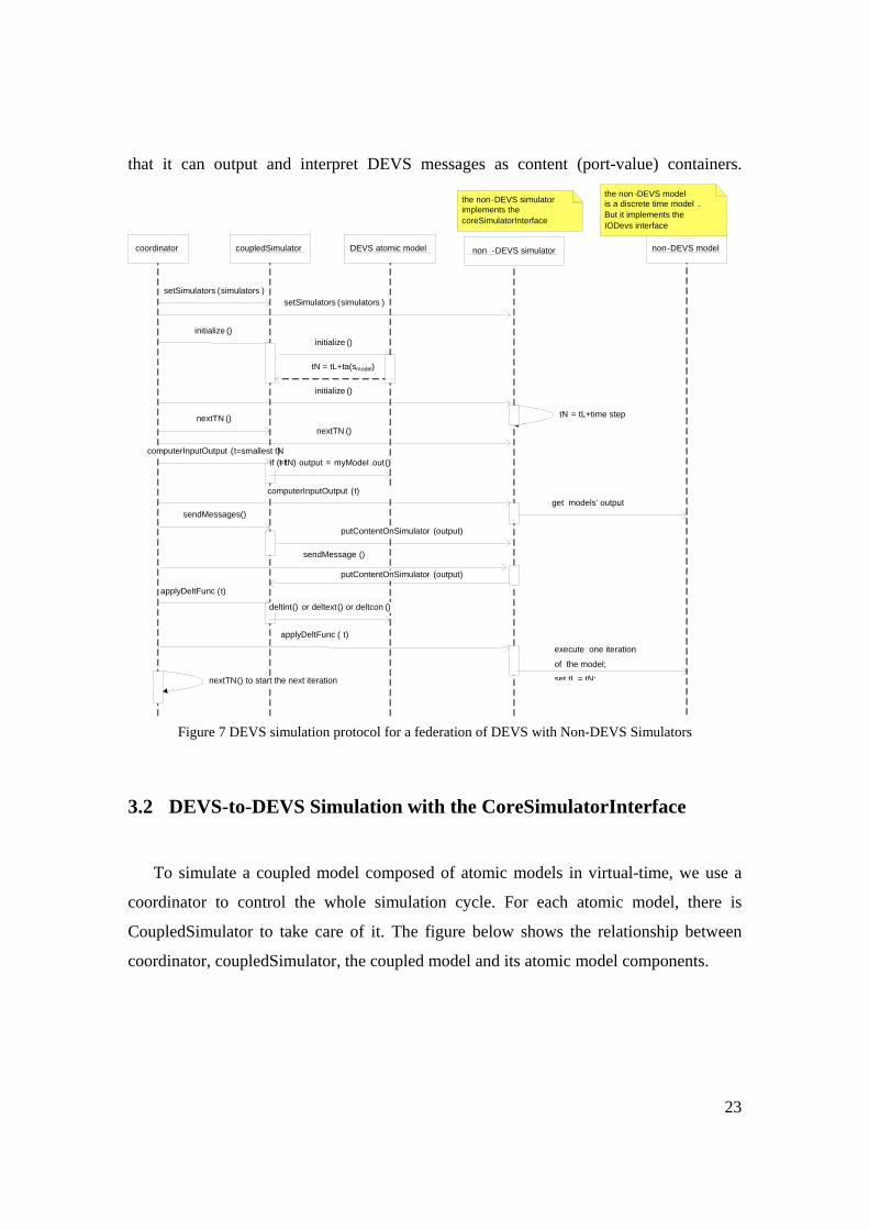
Figure 6 displays a sequence diagram to illustrate how a DEVS simulator can work with
a non-DEVS simulator where both implement the coreSimulatorInterface described
above. The entire simulation is coordinated by a coordinator following the simulation
protocol described in section 3.1. The DEVS simulator has been assigned a DEVS
atomic model and therefore implements the coupledSimulatorInterface. The non-DEVS
simulator is assumed to iterate a model with a fixed time step, although the model need
not be easily separable from the simulator. The discrete time model underlying the non-
DEVS simulator is assumed to generate output and be capable of interpreting input at
every iteration. Moveover, the model is assumed to implement the IODevs interface so
23
that it can output and interpret DEVS messages as content (port-value) containers.
Figure 7 DEVS simulation protocol for a federation of DEVS with Non-DEVS Simulators
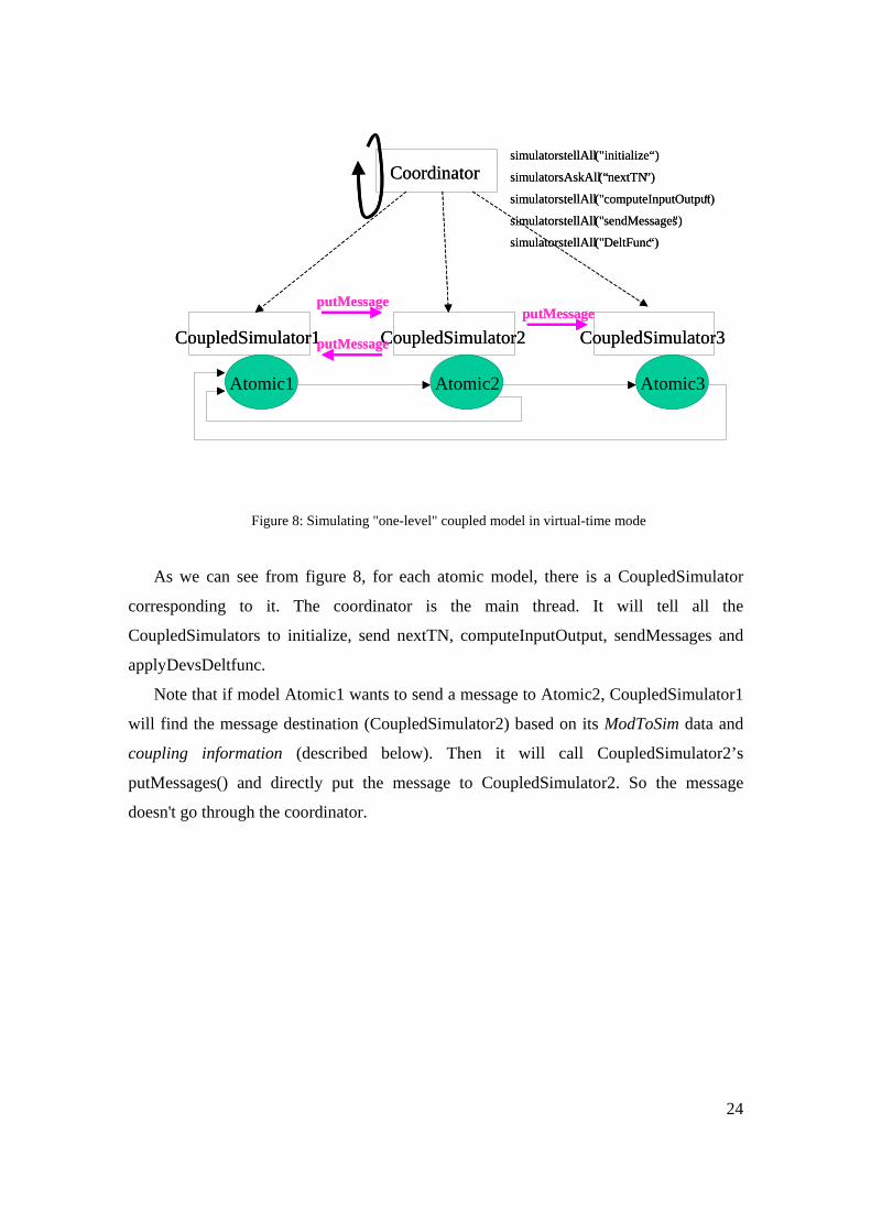
3.2 DEVS-to-DEVS Simulation with the CoreSimulatorInterface
To simulate a coupled model composed of atomic models in virtual-time, we use a
coordinator to control the whole simulation cycle. For each atomic model, there is
CoupledSimulator to take care of it. The figure below shows the relationship between
coordinator, coupledSimulator, the coupled model and its atomic model components.
coordinator coupledSimulator DEVS atomic model non -DEVS simulator non - DEVS model
setSimulators ( simulators )setSimulators ( simulators )
initialize () initialize ()
tN = tL+ta(smodel)
initialize () tN = tL+time stepnextTN ()
nextTN () computerInputOutput ( t=smallest tN )
computerInputOutput ( t)get models’ output . sendMessages()
putContentOnSimulator (output)
sendMessage ()
putContentOnSimulator (output)
applyDeltFunc ( t)
applyDeltFunc ( t) deltint () or deltext() or deltcon ()
if (t f = tN ) output = myModel .out()
.execute one iteration
of the model;
set tL = tN;nextTN () to start the next iteration
the non-DEVS simulatorimplements the coreSimulatorInterface
the non - DEVS modelis a discrete time model . But it implements the IODevs interface
24
Figure 8: Simulating "one-level" coupled model in virtual-time mode
As we can see from figure 8, for each atomic model, there is a CoupledSimulator
corresponding to it. The coordinator is the main thread. It will tell all the
CoupledSimulators to initialize, send nextTN, computeInputOutput, sendMessages and
applyDevsDeltfunc.
Note that if model Atomic1 wants to send a message to Atomic2, CoupledSimulator1
will find the message destination (CoupledSimulator2) based on its ModToSim data and
coupling information (described below). Then it will call CoupledSimulator2’s
putMessages() and directly put the message to CoupledSimulator2. So the message
doesn't go through the coordinator.
Coordinator
CoupledSimulator1
Atoimc1
CoupledSimulator3
Atoimc3
CoupledSimulator2
Atoimc2
simulators.tellAll("initialize“) simulators.AskAll(“nextTN ”)
simulators.tellAll("computeInputOutput “) simulators.tellAll("sendMessages ") simulators.tellAll("DeltFunc “)
putMessageputMessage
putMessage
Coordinator
CoupledSimulator1
Atomic1
CoupledSimulator3
Atomic3
CoupledSimulator2
Atomic2
simulators.tellAll("initialize“) simulators.AskAll(“nextTN ”)
simulators.tellAll("computeInputOutput “) simulators.tellAll("sendMessages ") simulators.tellAll("DeltFunc “)
putMessageputMessage
putMessage
25
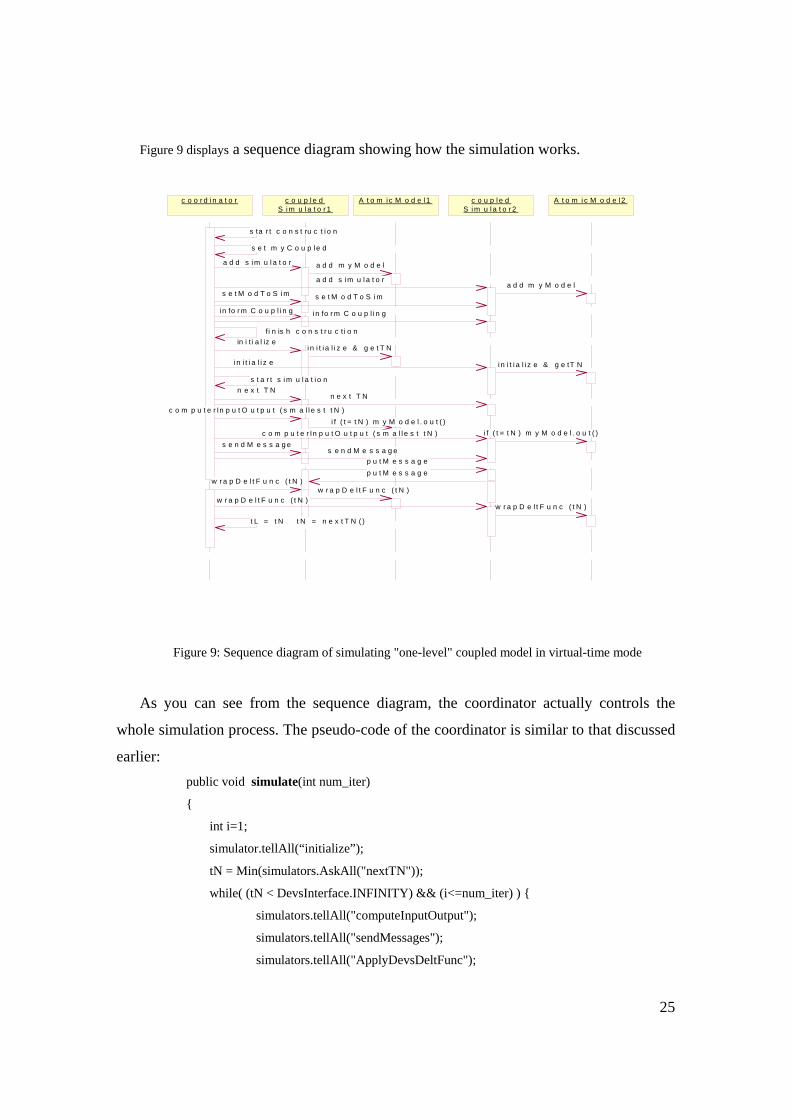
Figure 9 displays a sequence diagram showing how the simulation works.
Figure 9: Sequence diagram of simulating "one-level" coupled model in virtual-time mode
As you can see from the sequence diagram, the coordinator actually controls the
whole simulation process. The pseudo-code of the coordinator is similar to that discussed
earlier: public void simulate(int num_iter)
{
int i=1;
simulator.tellAll(“initialize”);
tN = Min(simulators.AskAll("nextTN"));
while( (tN < DevsInterface.INFINITY) && (i<=num_iter) ) {
simulators.tellAll("computeInputOutput");
simulators.tellAll("sendMessages");
simulators.tellAll("ApplyDevsDeltFunc");
c o o r d i n a t o r c o u p l e dS i m u l a t o r 1
A t o m i c M o d e l 1 c o u p l e dS i m u l a t o r 2
A t o m i c M o d e l 2
s ta r t c o n s t ru c t i o n
s e t m y C o u p l e d
a d d s i m u l a t o r a d d m y M o d e l
a d d s i m u l a t o ra d d m y M o d e l
s e t M o d T o S i m s e t M o d T o S i m
i n fo r m C o u p l i n g i n fo r m C o u p l i n g
fi n is h c o n s t r u c t i o nin i t i a l iz e
i n i t i a l i z e & g e t T N
i n i t i a l i z e i n i t i a l i z e & g e tT N
s t a r t s i m u l a t i o nn e x t T N
n e x t T N
c o m p u t e r In p u t O u t p u t ( s m a l l e s t t N )i f ( t = t N ) m y M o d e l . o u t ( )
c o m p u t e r In p u t O u t p u t ( s m a l l e s t t N ) i f ( t = t N ) m y M o d e l . o u t ( )s e n d M e s s a g e
s e n d M e s s a g ep u t M e s s a g ep u t M e s s a g e
w r a p D e l t F u n c ( t N )w r a p D e l t F u n c ( t N )
w r a p D e l t F u n c ( t N )w r a p D e l t F u n c ( t N )
t L = t N t N = n e x t T N ( )
26
tN = Min(simulators.AskAll("nextTN"));
i++;
}
}
From figure 9 we can also see that in coordinator’s construction phase, for each
atomic model, it will add a CoupledSimulator. Then it will call the setModToSim() and
informCoupling() to download the modelToSim data and coupling information to all the
CoupledSimulators. Here the modelToSim data stores the mapping information between
each model and its corresponding simulator. The coupling information records the
mapping information between one model’s output port and another model’s input port so
we know where the message will flow to. By having these two data tables (the
coordinator downloads it to the simulators), a simulator can send its model’s output
message directly to another simulator. Specifically, in CoupledSimulator’s
sendMessages(), if there are output messages generated by its model, the
CoupledSimulator will first find the message’s destination model based on the coupling
information. Then it will find the corresponding simulator of that model based on the
modelTosim data. Finally it will call that simulator’s putContentOnSimulator () to put the
contents of a message on the input of that simulator. Below we show the sendMessages()
and putContentOnSimulator () functions.
public void sendMessages() {
MessageInterface o = getOutput();
if( o!= null && !o.isEmpty()) {
Relation r = convertMsg((message)getOutput());//assume computeInputOutput done first
Iterator rit = r.iterator();
while (rit.hasNext()){
Pair p = (Pair)rit.next();
content co = (content)p.getValue();
Object ds = p.getKey();
CoreSimulatorInterface sim = modelToSim.get(ds);
Sim.putContentOnSimulator(co);
}
}
27
public void putContentOnSimulator (ContentInterface c){
input.add(c);
}
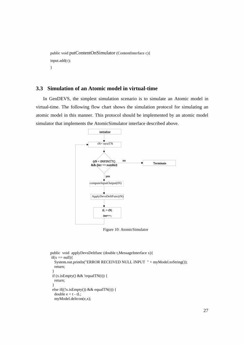
3.3 Simulation of an Atomic model in virtual-time
In GenDEVS, the simplest simulation scenario is to simulate an Atomic model in
virtual-time. The following flow chart shows the simulation protocol for simulating an
atomic model in this manner. This protocol should be implemented by an atomic model
simulator that implements the AtomicSimulator interface described above.
Figure 10: AtomicSimulator
public void applyDevsDeltfunc (double t,MessageInterface x){ if(x == null){ System.out.println("ERROR RECEIVED NULL INPUT " + myModel.toString()); return; } if (x.isEmpty() && !equalTN(t)) { return; } else if((!x.isEmpty()) && equalTN(t)) { double e = t - tL; myModel.deltcon(e,x);
tL = tN;
iter++;
ApplyDevsDeltFunc(tN)
initialize
( tN < INFINITY) && ( iter <= numIter) Terminate
yes
no
tN= nextTN
computeInputOutput(tN)
tL = tN;
iter++;
initialize
( tN < INFINITY) && ( iter <= numIter) Terminate
yes
no
28
} else if(equalTN(t)) { myModel.deltint(); } else if(!x.isEmpty()) { double e = t - tL; myModel.deltext(e,x); } tL = t; tN = tL + myModel.ta(); }
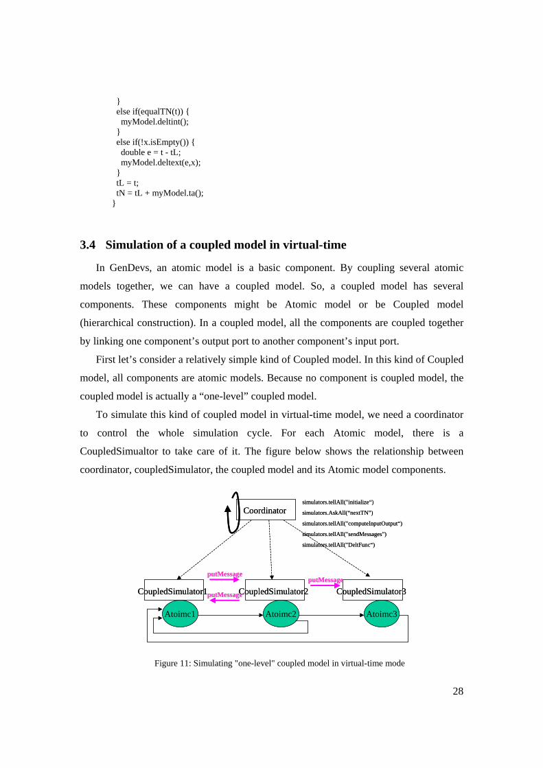
3.4 Simulation of a coupled model in virtual-time
In GenDevs, an atomic model is a basic component. By coupling several atomic
models together, we can have a coupled model. So, a coupled model has several
components. These components might be Atomic model or be Coupled model
(hierarchical construction). In a coupled model, all the components are coupled together
by linking one component’s output port to another component’s input port.
First let’s consider a relatively simple kind of Coupled model. In this kind of Coupled
model, all components are atomic models. Because no component is coupled model, the
coupled model is actually a “one-level” coupled model.
To simulate this kind of coupled model in virtual-time model, we need a coordinator
to control the whole simulation cycle. For each Atomic model, there is a
CoupledSimualtor to take care of it. The figure below shows the relationship between
coordinator, coupledSimulator, the coupled model and its Atomic model components.
Figure 11: Simulating "one-level" coupled model in virtual-time mode
Coordinator
CoupledSimulator1
Atoimc1
CoupledSimulator3
Atoimc3
CoupledSimulator2
Atoimc2
simulators.tellAll("initialize“)
simulators.AskAll(“nextTN”)
simulators.tellAll("computeInputOutput“)
simulators.tellAll("sendMessages")
simulators.tellAll("DeltFunc“)
putMessageputMessage
putMessage
Coordinator
CoupledSimulator1
Atoimc1
CoupledSimulator3
Atoimc3
CoupledSimulator2
Atoimc2
simulators.tellAll("initialize“)
simulators.AskAll(“nextTN”)
simulators.tellAll("computeInputOutput“)
simulators.tellAll("sendMessages")
simulators.tellAll("DeltFunc“)
putMessageputMessage
putMessage
29
As we can see from figure 8, for each atomic model, there is a CoupledSimulator
corresponding to it. The coordinator is the main thread. It will tell all the
CoupledSimulators to initialize, send nextTN, computeInputOutput, sendMessages and
wrapDeltfunc.
Note that if model Atomic1 wants to send a message to Atomic2, CoupledSimulator1
will find the message destination (CoupledSimulator2) based on its ModToSim data and
coupling information (described below). Then it will call CoupledSimulator2’s
putMessages() and directly put the message to CoupledSimulator2. So the message
doesn't go through the coordinator.
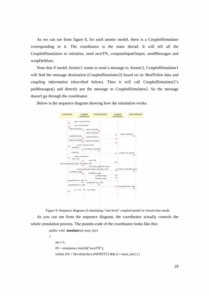
Below is the sequence diagram showing how the simulation works.
Figure 9: Sequence diagram of simulating "one-level" coupled model in virtual-time mode
As you can see from the sequence diagram, the coordinator actually controls the
whole simulation process. The psuedo-code of the coordinator looks like this: public void simulate(int num_iter)
{
int i=1;
tN = simulators.AskAll("nextTN");
while( (tN < DevsInterface.INFINITY) && (i<=num_iter) ) {
c oordinator c oupledS im ulator1
A tom ic M odel1 c oupledS im ulator2
A tom ic M odel2
s ta rt c onst ruc t ion
s et m y Coupled
add s im ulator add m y M odel
add s im ulatoradd m y M odel
s etM odToS im s etM odToS im
inform Coupling inform Coupling
fi n is h c ons tru c ti onini ti al iz e
init ia liz e & getTN
init ia liz e init ia liz e & getTN
s tart s im ulat ionn ex t TN
nex t TN
c om puterInputO utput (s m alles t tN)if (t= tN) m y M odel.out()
c om puterInputO utput (s m alles t tN) if (t= tN) m y M odel.out()s endM es s age
s endMe s s ageputM es s ageputM es s age
wrapDeltFunc (tN)wrapDeltFunc (tN)
wrapDeltFunc (tN)wrapDeltFunc (tN)
tL = tN tN = nex tTN()
30
simulators.tellAll("computeInputOutput");
simulators.tellAll("sendMessages");
simulators.tellAll("DeltFunc");
tN = simulators.AskAll("nextTN");
i++;
}
}
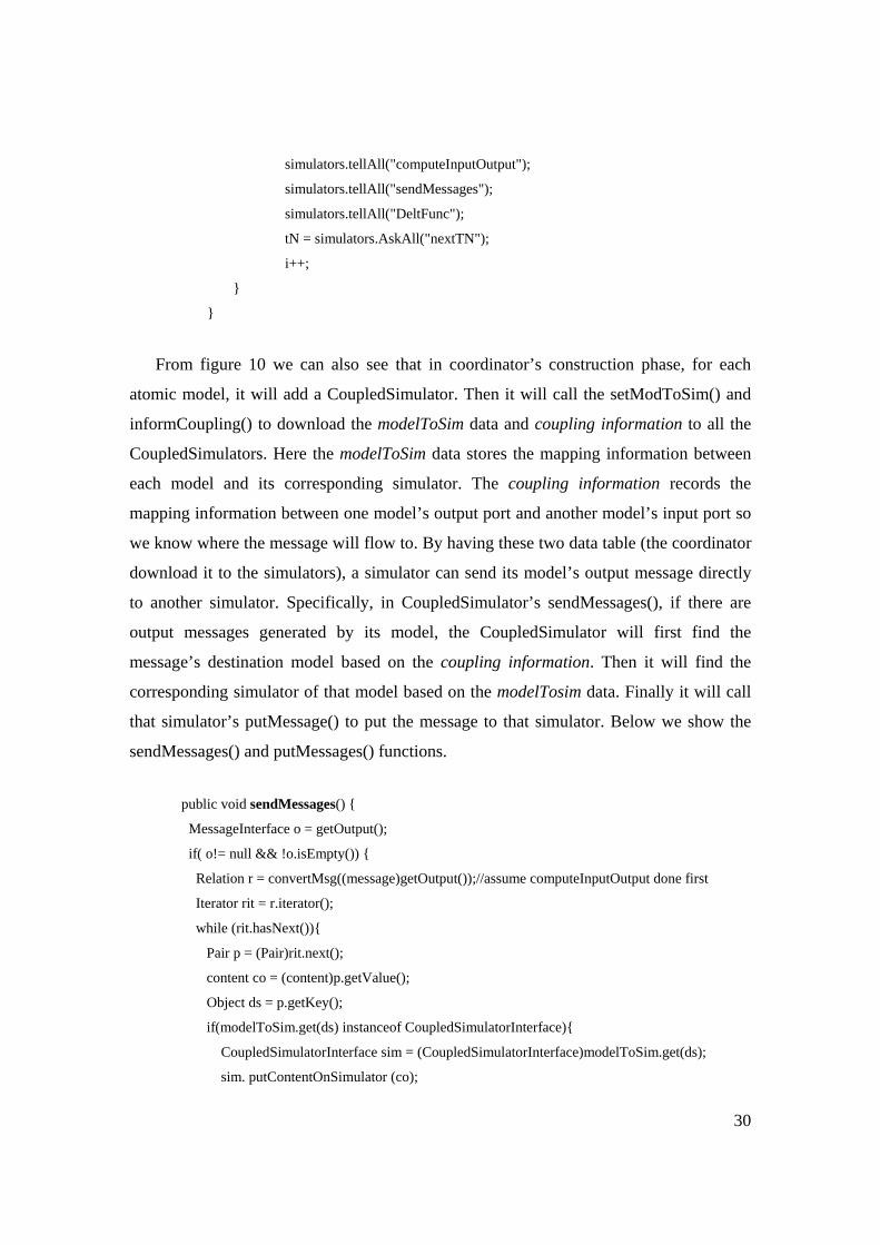
From figure 10 we can also see that in coordinator’s construction phase, for each
atomic model, it will add a CoupledSimulator. Then it will call the setModToSim() and
informCoupling() to download the modelToSim data and coupling information to all the
CoupledSimulators. Here the modelToSim data stores the mapping information between
each model and its corresponding simulator. The coupling information records the
mapping information between one model’s output port and another model’s input port so
we know where the message will flow to. By having these two data table (the coordinator
download it to the simulators), a simulator can send its model’s output message directly
to another simulator. Specifically, in CoupledSimulator’s sendMessages(), if there are
output messages generated by its model, the CoupledSimulator will first find the
message’s destination model based on the coupling information. Then it will find the
corresponding simulator of that model based on the modelTosim data. Finally it will call
that simulator’s putMessage() to put the message to that simulator. Below we show the
sendMessages() and putMessages() functions.
public void sendMessages() {
MessageInterface o = getOutput();
if( o!= null && !o.isEmpty()) {
Relation r = convertMsg((message)getOutput());//assume computeInputOutput done first
Iterator rit = r.iterator();
while (rit.hasNext()){
Pair p = (Pair)rit.next();
content co = (content)p.getValue();
Object ds = p.getKey();
if(modelToSim.get(ds) instanceof CoupledSimulatorInterface){
CoupledSimulatorInterface sim = (CoupledSimulatorInterface)modelToSim.get(ds);
sim. putContentOnSimulator (co);
31
}
}
public void putContentOnSimulator (ContentInterface c){
input.add(c);
}
4 Future Development Reference [1] provides a description of DEVSJAVA architecture that includes
capabilities for real-time and distributed simulation of hierarchical models, a more
extensive scope than is covered in this reformulation as a DEVS standard for
implementation. We feel it is important to get the basic level discussed here formulated
and agreed to by the DEVS community before proceeding on to incorporate the more
extensive capabilities that can be built on top of it.
5 References
[1]The Architecture of GenDevs Distributed Simulation in DEVSJAVA, Xiaolin Hu
Dept of Computer Science, Georgia State University, Updated by Bernard P. Zeigler
ACIMS, January 2008 Available at www.acims.arizona.edu
[2]Bernard P. Zeigler, Objects and Systems: Principled Design with Implementation C++/Java,
Springer-Verlag, NY, 1997.