a prototype fingertip with high spatial resolution ... · a prototype fingertip with high spatial...
TRANSCRIPT
A Prototype Fingertip with High Spatial ResolutionPressure Sensing for the Robot iCub
Alexander Schmitz 1, Marco Maggiali 1, Marco Randazzo 1, Lorenzo Natale 1 and Giorgio Metta 1,2
1Italian Institute of Technology, Italy2DIST, University of Genoa, Italy
alexander.schmitz, marco.maggiali, marco.randazzo, lorenzo.natale, [email protected]
Abstract— Tactile feedback is of crucial importance for objectmanipulation in unknown environments. In this paper we de-scribe the design and realization of a fingertip which includes acapacitive pressure sensor with 12 sensitive zones. It is naturallyshaped and its size is small enough so that it can be mountedon the fingers of the humanoid robot iCub. It also embedsthe electronic device which performs A/D conversion: This isbeneficial for the signal to noise ratio and reduces the number ofwires required to connect the fingertip to the robot. The fingertipis made of silicone, which makes its surface and inner structurecompliant and flexible. We present preliminary experimentsperformed with the first prototype.
I. INTRODUCTION
Robotic agents can manipulate objects quickly, preciselyand reliably in controlled settings, such as industrial environ-ments. However, they often fail to achieve such abilities inunknown environments, or with novel objects. Humans, onthe other hand, are consistently skillful at such actions. Oneof the reasons why current robotic systems lag behind is thatthey lack accurate and precise tactile feedback.
Therefore, to achieve human-like object manipulation, arobotic hand not only needs a high degree of actuation (i.e.many degrees of freedom), but should be also equipped withsophisticated haptic sensors [1]. This sensory information isessential for adapting the grasp, and in addition can be usedto actively explore the object in-hand. Thus, it is possibleto obtain information about objects that is hard or evenimpossible to acquire through other sensing modalities such asvision or sound. This is important because grasping and objectmanipulation do not depend only on visible properties such assize, orientation and shape, but also, for example, on weight,slipperiness, texture and hardness. Even visible features, suchas the shape and the edges of an object, are sometimes easierto detect with haptic sensors.
In general, object manipulation enables active object ex-ploration and induces sensory-motor correlations. Many re-searchers see perception as an active process, where an agentactively structures its own sensory input by manipulating theworld to obtain “good” sensory data, enabling categorization,adaptation and learning (see for example [2][3][4]).
Another important aspect when designing a robotic hand iscompliance. On the one hand, planning movements accuratelybeforehand is often too hard, on the other feedback control isoften too slow to affect control appropriately [5][6]. A number
of researchers therefore have started to emphasize the role ofpassive compliance (for example through the use of elasticmaterials) for dealing with uncertainties [7][8][9][10]. Evenin the absence of sophisticated control, passive compliancefacilitates movements in unknown environments.
Therefore, passive compliance is an important basis forgrasping. It has the benefit of immediate response withoutany time-delay and no computational effort. The graspingtask is split up between the controller and the morphologyof the robot. A compliant finger leads to the compensationof small errors in the configuration of the grasp. This allows,for example, faster grasping movements and a more robusthandling of objects. It creates grasp adaptability and stability,and provides protection against impacts [11].
When the compliant material is attached on top of thesensory surface, the drawback is that it acts as a low pass filterwhich reduces the spatial resolution of the sensor [1]. It wouldbe therefore beneficial if no material was mounted on top ofthe transducer, but instead the transducer was compliant, andadditionally was also mountable on top of a flexible material.
A number of robotic hands for object manipulation havebeen built. For example, the 6-axis force sensor used in DLR-HIT hand [12], the GIFU III hand [13] and the 3-axis forcesensor in the Paloma hand [14] can measure pressure and shearforces. The GIFU III hand has 859 sensing points, howeverbecause of the nature of the sensors, the skin is not softand the signal conditioning happens at a distance from thesensitive area. The Obrero hand [15] has 40 contact pointswhich embeds 4 sensors each. The Shadow hand [16] has ahigh dexterity, comparable to that of the human hand. It alsohas a high number of sensors in its fingertips (based on QTCtechnology) and adjustable compliance in the actuation systemwhich is pneumatic.
II. THE HANDS OF THE HUMANOID ROBOT ICUB
The fingertip described here will be mounted on the hu-manoid robot iCub [17] (see also Figure 1). iCub has acomplete body with two legs, two arms, two hands and ahead. It has 53 controllable degrees of freedom altogether,9 of which belong to each hand, excluding the wrist. Therobot is about 1m tall, that is roughly the size of a three anda half years old child. It is equipped with an active stereo
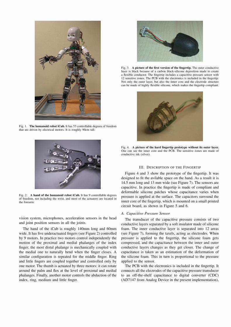
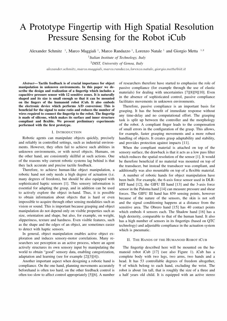
Fig. 1. The humanoid robot iCub. It has 53 controllable degrees of freedomthat are driven by electrical motors. It is roughly 90cm tall.
Fig. 2. A hand of the humanoid robot iCub. It has 9 controllable degreesof freedom, not including the wrist, and most of the actuators are located inthe forearm.
vision system, microphones, acceleration sensors in the headand joint position sensors in all the joints.
The hand of the iCub is roughly 140mm long and 60mmwide. It has five underactuated fingers (see Figure 2) controlledby 9 motors. In practice two motors control independently themotion of the proximal and medial phalanges of the indexfinger; the most distal phalange is mechanically coupled withthe medial one to naturally bend when the finger closes. Asimilar configuration is repeated for the middle finger. Ringand little fingers are coupled together and controlled only byone motor. The thumb is actuated by three motors: it can rotatearound the palm and flex at the level of proximal and medialphalanges. Finally, another motor controls the abduction of theindex, ring, medium and little finger.
Fig. 3. A picture of the first version of the fingertip. The outer conductivelayer is black because of a carbon black-silicone deposition made to createa flexible conductor. The fingertip includes a capacitive pressure sensor with12 sensitive zones. The PCB with the electronics is included in the fingertip.Not only the outer layer, but also the inner core and the electrode structurecan be made of highly flexible silicone, which makes the fingertip compliant.
Fig. 4. A picture of the hard fingertip prototype without its outer layer.One can see the inner core and the PCB. The sensitive zones are made ofconductive ink (silver).
III. DESCRIPTION OF THE FINGERTIP
Figure 4 and 3 show the prototype of the fingertip. It wasdesigned to fit the avilable space on the hand. As a result it is14.5 mm long and 13 mm wide (see Figure 7). The sensors arecapacitive. In practice the fingertip is made of compliant anddeformable silicone patches whose capacitance varies whenpressure is applied at the surface. The capacitors surround theinner core of the fingertip, which is mounted on a small printedcircuit board, as shown in Figure 5 and 6.
A. Capacitive Pressure Sensor
The transducer of the capacitive pressure consists of twoconductive layers separated by a soft insulator made of siliconefoam. The inner conductive layer is separated into 12 areas(see Figure 7), forming the taxels, acting as electrodes. Whenpressure is applied to the fingertip, the silicone foam getscompressed, and the capacitance between the inner and outerconductive layers changes as they get closer. The change ofcapacitance is taken as an estimation of the deformation ofthe silicone foam. This in turn is proportional to the pressureapplied to the sensor.
The PCB with the electronics is included in the fingertip. Itconnects all the electrodes of the capacitive pressure transducerto an off-the-shelf capacitance to digital converter (CDC)(AD7147 from Analog Device in the present implementation),
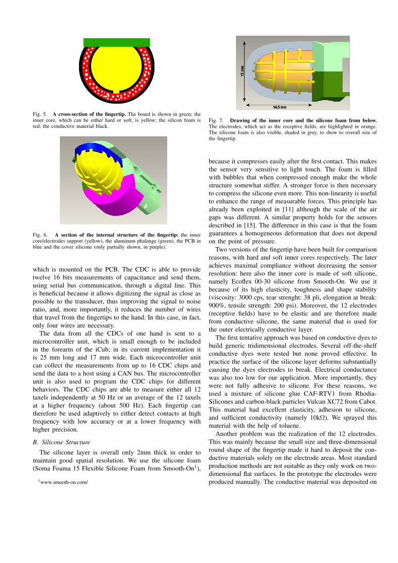
Fig. 5. A cross-section of the fingertip. The board is shown in green; theinner core, which can be either hard or soft, is yellow; the silicon foam isred; the conductive material black.
Fig. 6. A section of the internal structure of the fingertip: the innercore/electrodes support (yellow), the aluminum phalange (green), the PCB inblue and the cover silicone (only partially shown, in purple).
which is mounted on the PCB. The CDC is able to providetwelve 16 bits measurements of capacitance and send them,using serial bus communication, through a digital line. Thisis beneficial because it allows digitizing the signal as close aspossible to the transducer, thus improving the signal to noiseratio, and, more importantly, it reduces the number of wiresthat travel from the fingertips to the hand. In this case, in fact,only four wires are necessary.
The data from all the CDCs of one hand is sent to amicrocontroller unit, which is small enough to be includedin the forearm of the iCub; in its current implementation itis 25 mm long and 17 mm wide. Each microcontroller unitcan collect the measurements from up to 16 CDC chips andsend the data to a host using a CAN bus. The microcontrollerunit is also used to program the CDC chips for differentbehaviors. The CDC chips are able to measure either all 12taxels independently at 50 Hz or an average of the 12 taxelsat a higher frequency (about 500 Hz). Each fingertip cantherefore be used adaptively to either detect contacts at highfrequency with low accuracy or at a lower frequency withhigher precision.
B. Silicone Structure
The silicone layer is overall only 2mm thick in order tomaintain good spatial resolution. We use the silicone foam(Soma Foama 15 Flexible Silicone Foam from Smooth-On1),
1www.smooth-on.com/
Fig. 7. Drawing of the inner core and the silicone foam from below.The electrodes, which act as the receptive fields, are highlighted in orange.The silicone foam is also visible, shaded in grey, to show to overall size ofthe fingertip.
because it compresses easily after the first contact. This makesthe sensor very sensitive to light touch. The foam is filledwith bubbles that when compressed enough make the wholestructure somewhat stiffer. A stronger force is then necessaryto compress the silicone even more. This non-linearity is usefulto enhance the range of measurable forces. This principle hasalready been exploited in [11] although the scale of the airgaps was different. A similar property holds for the sensorsdescribed in [15]. The difference in this case is that the foamguarantees a homogeneous deformation that does not dependon the point of pressure.
Two versions of the fingertip have been built for comparisonreasons, with hard and soft inner cores respectively. The laterachieves maximal compliance without decreasing the sensorresolution: here also the inner core is made of soft silicone,namely Ecoflex 00-30 silicone from Smooth-On. We use itbecause of its high elasticity, toughness and shape stability(viscosity: 3000 cps, tear strenght: 38 pli, elongation at break:900%, tensile strength: 200 psi). Moreover, the 12 electrodes(receptive fields) have to be elastic and are therefore madefrom conductive silicone, the same material that is used forthe outer electrically conductive layer.
The first tentative approach was based on conductive dyes tobuild generic tridimensional electrodes. Several off-the-shelfconductive dyes were tested but none proved effective. Inpractice the surface of the silicone layer deforms substantiallycausing the dyes electrodes to break. Electrical conductancewas also too low for our application. More importantly, theywere not fully adhesive to silicone. For these reasons, weused a mixture of silicone glue CAF-RTV1 from Rhodia-Silicones and carbon-black particles Vulcan XC72 from Cabot.This material had excellent elasticity, adhesion to silicone,and sufficient conductivity (namely 10kΩ). We sprayed thismaterial with the help of toluene.
Another problem was the realization of the 12 electrodes.This was mainly because the small size and three-dimensionalround shape of the fingertip made it hard to deposit the con-ductive materials solely on the electrode areas. Most standardproduction methods are not suitable as they only work on two-dimensional flat surfaces. In the prototype the electrodes wereproduced manually. The conductive material was deposited on
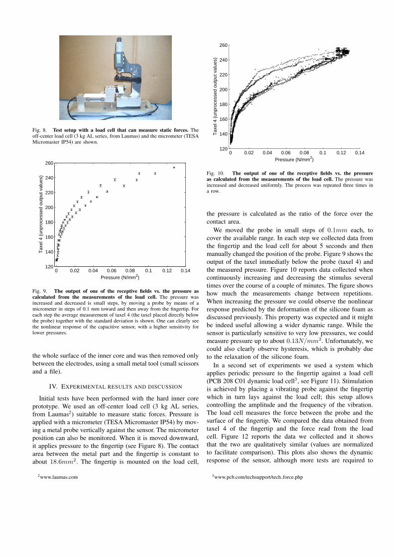
Fig. 8. Test setup with a load cell that can measure static forces. Theoff-center load cell (3 kg AL series, from Laumas) and the micrometer (TESAMicromaster IP54) are shown.
0 0.02 0.04 0.06 0.08 0.1 0.12 0.14120
140
160
180
200
220
240
260
Pressure (N/mm2)
Tax
el 4
(un
proc
esse
d ou
tput
val
ues)
Fig. 9. The output of one of the receptive fields vs. the pressure ascalculated from the measurements of the load cell. The pressure wasincreased and decreased is small steps, by moving a probe by means of amicrometer in steps of 0.1 mm toward and then away from the fingertip. Foreach step the average measurement of taxel 4 (the taxel placed directly belowthe probe) together with the standard deviation is shown. One can clearly seethe nonlinear response of the capacitive sensor, with a higher sensitivity forlower pressures.
the whole surface of the inner core and was then removed onlybetween the electrodes, using a small metal tool (small scissorsand a file).
IV. EXPERIMENTAL RESULTS AND DISCUSSION
Initial tests have been performed with the hard inner coreprototype. We used an off-center load cell (3 kg AL series,from Laumas2) suitable to measure static forces. Pressure isapplied with a micrometer (TESA Micromaster IP54) by mov-ing a metal probe vertically against the sensor. The micrometerposition can also be monitored. When it is moved downward,it applies pressure to the fingertip (see Figure 8). The contactarea between the metal part and the fingertip is constant toabout 18.6mm2. The fingertip is mounted on the load cell,
2www.laumas.com
0 0.02 0.04 0.06 0.08 0.1 0.12 0.14120
140
160
180
200
220
240
260
Pressure (N/mm2)
Tax
el 4
(un
proc
esse
d ou
tput
val
ues)
Fig. 10. The output of one of the receptive fields vs. the pressureas calculated from the measurements of the load cell. The pressure wasincreased and decreased uniformly. The process was repeated three times ina row.
the pressure is calculated as the ratio of the force over thecontact area.
We moved the probe in small steps of 0.1mm each, tocover the available range. In each step we collected data fromthe fingertip and the load cell for about 5 seconds and thenmanually changed the position of the probe. Figure 9 shows theoutput of the taxel immediatly below the probe (taxel 4) andthe measured pressure. Figure 10 reports data collected whencontinuously increasing and decreasing the stimulus severaltimes over the course of a couple of minutes. The figure showshow much the measurements change between repetitions.When increasing the pressure we could observe the nonlinearresponse predicted by the deformation of the silicone foam asdiscussed previously. This property was expected and it mightbe indeed useful allowing a wider dynamic range. While thesensor is particularly sensitive to very low pressures, we couldmeasure pressure up to about 0.13N/mm2. Unfortunately, wecould also clearly observe hysteresis, which is probably dueto the relaxation of the silicone foam.
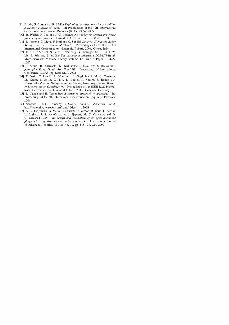
In a second set of experiments we used a system whichapplies periodic pressure to the fingertip against a load cell(PCB 208 C01 dynamic load cell3, see Figure 11). Stimulationis achieved by placing a vibrating probe against the fingertipwhich in turn lays against the load cell; this setup allowscontrolling the amplitude and the frequency of the vibration.The load cell measures the force between the probe and thesurface of the fingertip. We compared the data obtained fromtaxel 4 of the fingertip and the force read from the loadcell. Figure 12 reports the data we collected and it showsthat the two are qualitatively similar (values are normalizedto facilitate comparison). This plots also shows the dynamicresponse of the sensor, although more tests are required to
3www.pcb.com/techsupport/tech force.php
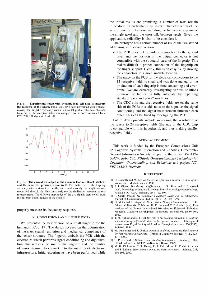
Fig. 11. Experimental setup with dynamic load cell used to measurethe response of the sensor. Initial tests have been performed with a shakermoving the fingertip vertically with a sinusoidal profile. The data obtainedfrom one of the receptive fields was compared to the force measured by aPCB 208 C01 dynamic load cell.
1 2 3 4 5 6 7 8 9 10 11
−0.8
−0.6
−0.4
−0.2
0
0.2
0.4
Time (s)
Fig. 12. The normalized output of the dynamic load cell (black, dashed)and the capacitive pressure sensor (red). The shaker moved the fingertipvertically with a sinusoidal profile, and simultaneously the amplitude wasmodulated sinusoidally. One can clearly see the similarities between the twomeasurements. The different amplitudes of the two signals stem solely fromthe different output ranges of the sensors.
properly measure its frequency response.
V. CONCLUSIONS AND FUTURE WORK
We presented the first version of a small fingertip for thehumanoid iCub [17]. The design focused on the optimizationof the size, spatial resolution and mechanical compliance ofthe sensor structure. The fingertip embeds the PCB with theelectronics which performs signal conditioning and digitaliza-tion: this reduces the size of the fingertip and the numberof wires required to connect it to the main robot electronicinfrastructure. Initial experiments have been performed: while
the initial results are promising, a number of tests remainto be done. In particular, a full-blown characterization of thesensor remains to be done including the frequency response ofthe single taxel and the cross-talk between taxels. Given theapplication, reliability is also to be considered.
The prototype has a certain number of issues that we startedaddressing in a second version:• The PCB does not provide a connection to the ground
layer and the position of the output connector is notcompatible with the structural parts of the fingertip. Thismakes difficult a proper connection of the fingertip onthe finger support. Clearly, this is an easy fix by movingthe connectors to a more suitable location.
• The space on the PCB for the electrical connections to the12 receptive fields is small and was done manually; theproduction of each fingertip is time consuming and error-prone. We are currently investigating various solutionsto make the fabrication fully automatic by exploitingstandard “pick and place” machines.
• The CDC chip and the receptive fields are on the sameside of the PCB; this adds noise to the signal as the signalconditioning and the signal measurement influence eachother. This can be fixed by redesigning the PCB.
Future developments include increasing the resolution ofthe sensor to 24 receptive fields (the size of the CDC chipis compatible with this hypothesis), and thus making smallerreceptive fields.
ACKNOWLEDGMENT
This work is funded by the European Commissions UnitE5 Cognitive Systems, Interaction and Robotics, Directorate-General Information Society, as part of the project IST-FP6-004370 RobotCub: ROBotic Open-architecture Technology forCognition, Understanding, and Behaviour and project ICT-FP7-215843 Poeticon.
REFERENCES
[1] H. Nicholls and M. Lee Tactile sensing for mechatronics - a state of theart survey. Mechatronics 9, 1999.
[2] J. J. Gibson The theory of affordances. R. Shaw and J. Bransford(eds), Perceiving, acting, and knowing: Toward an ecological psychology.Hillsdale, NJ, USA: Erlbaum, pp 67-82, 1977.
[3] P. Cisek, Beyond the computer metaphor: Behaviour as interaction.Journal of Consciousness Studies, 6(11), 125-142, 1999.
[4] G. Metta and P. Fitzpatrick Better Vision Through Manipulation. C. G.Prince, Y. Demiris, Y. Marom, H. Kozima and C. Balkenius (eds), Pro-ceedings of the Second International Workshop on Epigenetic Robotics:Modeling Cognitive Development in Robotic Systems 94, pp 97-104,2002.
[5] T. M. Kubow and R. J. Full The role of the mechanical system in control:a hypothesis of self-stabilization in hexapedal runners. Philosophicaltransactions- Royal Society of London. Biological sciences, 354(1385),849-861, 1999.
[6] M. Desmurget and S. Grafton Forward modeling allows feedback controlfor fast reaching movements. Trends in Cognitive Sciences, 4(11), 423-431, 2000.
[7] R. Pfeifer and C. Scheier Understanding Intelligence. Cambridge, MA,USA/London, UK: MIT Press/Bradford Books, 1999.
[8] M. H. Dickinson, C. T. Farley, R. J. Full, M. A. R. Koehl, R. Kramand S. Lehman How animals move: an integrative view. Science, 288,100-106, 2000.
[9] F. Iida, G. Gomez and R. Pfeifer Exploiting body dynamics for controllinga running quadruped robot. In: Proceedings of the 12th InternationalConference on Advanced Robotics (ICAR 2005), 2005.
[10] R. Pfeifer, F. Iida and J. C. Bongard New robotics: Design principlesfor intelligent systems. Journal of Artificial Life, 11, 99-120, 2005.
[11] L. Jamone, G. Metta, F. Nori and G. Sandini James: A Humanoid RobotActing over an Unstructured World. Proceedings of 6th IEEE-RASInternational Conference on Humanoid Robots, 2006, Genoa, Italy.
[12] H. Liu, P. Meusel, N. Seitz, B. Willberg, G. Hirzinger, M. H. Jin, Y. W.Liu, R. Wei and Z. W. Xie The modular multisensory DLR-HIT-Hand.Mechanism and Machine Theory, Volume 42, Issue 5, Pages 612-625,2007.
[13] T. Mouri, H. Kawasaki, K. Yoshikawa, J. Takai and S. Ito Anthro-pomorphic Robot Hand: Gifu Hand III. Proceedings of InternationalConference ICCAS, pp 1288-1293, 2002.
[14] P. Dario, C. Laschi, A. Menciassi, E. Guglielmelli, M. C. Carrozza,M. Zecca, L. Zollo, G. Teti, L. Beccai, F. Vecchi, S. Roccella AHuman-like Robotic Manipulation System Implementing Human Modelsof Sensory-Motor Coordination. Proceedings of 3th IEEE-RAS Interna-tional Conference on Humanoid Robots, 2003, Karlsruhe, Germany.
[15] L. Natale and E. Torres-Jara A sensitive approach to grasping. In:Proceedings of the 6th International Conference on Epigenetic Robotics,2006.
[16] Shadow Hand Company [Online] Shadow dexterous hand.http://www.shadowrobot.com/hand/, March 1, 2008
[17] N. G. Tsagarakis, G. Metta, G. Sandini, D. Vernon, R. Beira, F. Becchi,L. Righetti, J. Santos-Victor, A. J. Ijspeert, M. C. Carrozza, and D.G. Caldwell iCub - the design and realization of an open humanoidplatform for cognitive and neuroscience research. International Journalof Advanced Robotics, Vol. 21 No. 10, pp. 1151-75, Oct. 2007.