a random network coding testbed: implementation … · a random network coding testbed:...
TRANSCRIPT

A random network coding testbed:Implementation And Performance
ResultsDubrovnik’2016
Selahattin Gökceli
(Joint work with Semiha Tedik Başaran and Güneş Karabulut Kurt)
ISTANBUL TECHNICAL UNIVERSITY
DEPARTMENT OF ELECTRONICS AND COMMUNICATIONS ENGINEERING
This work is supported by TUBITAK under Grant 113E294.
1

Outline
• Main Concepts– Network Coding
– Cooperative Networking
– Cooperative Network Coding
• Wireless Network Coded Systems– System Model
– Random Network Coding
• Testbed Studies– Testbed Deployment-Details
– Image Transmission Example
– Test Results
• Conclusions
2

An Option: Network Coding (1/2)
• Conventional communication systems:– Network nodes function independently
• Routing, error control coding and data storage have been designed in accordance with this independency principle
• Data flow rates from source nodes to destination nodes in a network can be increased by transmitting combinations of data [1]
• Stemming from the early works of in the form of multi-level diversity [2]
[1] R. Ahlswede, N. Cai, S.-Y. Li, and R. Yeung, “Network information flow,” IEEE Trans. Inf. Theory, vol. 46, no. 4, pp. 1204–1216, July 2000. [2] R. Yeung, “Multilevel diversity coding with distortion,” Information Theory, IEEE Transactions on, vol. 41, no. 2, pp. 412–422, Mar 1995.
3

An Option: Network Coding (2/2)
• Generalized set-up:1. BROADCAST PHASE
Source nodes transmit information symbols in N orthogonal resource block (time slots or frequency channels) during the multiple access phase (solid black lines) to relay nodes.
2. RELAYING PHASEN relay nodes perform network coding on the M estimated symbols and transmit in N resource blocks in the to destination
4

The majority of the literature on network coding targets wired networks
(or application layer deployments )
Assumption: no erroneous transmissions
What about error propagation?
5
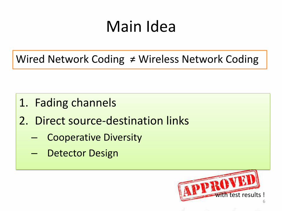
Main Idea
Wired Network Coding ≠ Wireless Network Coding
1. Fading channels
2. Direct source-destination links
– Cooperative Diversity
– Detector Design
6with test results !

Cooperative Networking
Network Coding
Network Coded Cooperation
+ Wireless Channels
7

Network Coded Cooperation
• Combining network coding and cooperative networking
• Can exploit the intrinsic characteristics of wireless networks to improve – Throughput
– Robustness.
• Based on the preliminary works of Chen, Kishore and Li in [4].
[4] Y. Chen, S. Kishore, and J. Li, “Wireless diversity through network coding,” WCNC 20068

Example: 4 source nodes, 4 relay nodes, broadcast transmission
9

Random Network Coding
• Random network coding
at relay nodes
• In presence of direct communication links decoding probability becomes
10
[6] S.Tedik Başaran, S. Gökceli, G.Karabulut Kurt, Enver Özdemir, Ergün Yaraneri, "Error Performance Analysis Random Network Coded Cooperative Systems in Wireless Channels,” in preparation
where 𝑢 = 𝑠𝑑, 𝑠𝑟, 𝑟𝑑
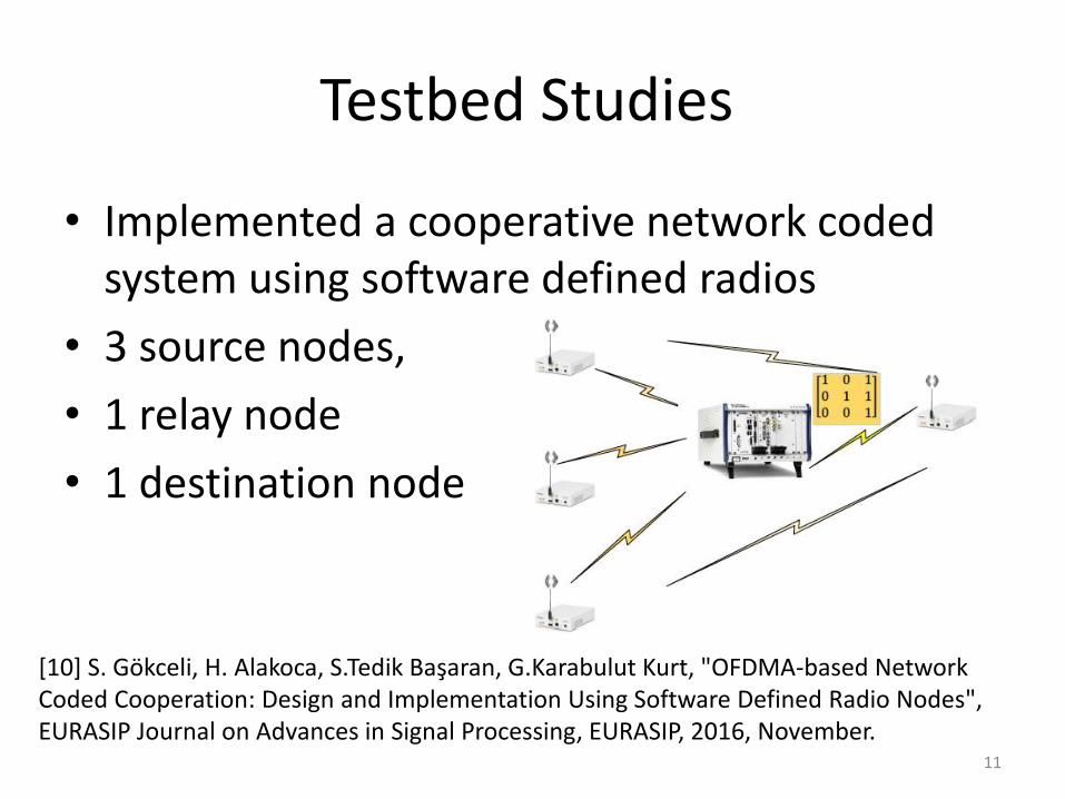
Testbed Studies
• Implemented a cooperative network coded system using software defined radios
• 3 source nodes,
• 1 relay node
• 1 destination node
11
[10] S. Gökceli, H. Alakoca, S.Tedik Başaran, G.Karabulut Kurt, "OFDMA-based Network Coded Cooperation: Design and Implementation Using Software Defined Radio Nodes", EURASIP Journal on Advances in Signal Processing, EURASIP, 2016, November.
Hardware Details (1/2)
Hardware Components:- NI USRP-2921: Source and Destination Nodes,
Instantaneous bandwidth up to 20 MHz
- NI PXIe-1082 Chassis:
- NI PXIe-5644R VST: Relay Node,
Instantaneous bandwidth up to 80 MHz
- NI PXI-6683: Clock Signal Source
12

Hardware Details (2/2)
Synchronization Solution:
- Three external 10 MHz signals are provided by NI
PXI-6683 Timing and Synchronization Module
- These signals are transmitted to two source nodes
and destination node via cables
- Remaining source node receives synchronization
signal through MIMO cable
- Synchronization configuration in code
13
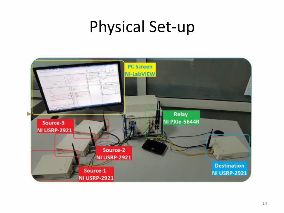
Physical Set-up
14
Testbed Details (1/8)
Software Component:
-LabVIEW Software: Visual Programming Language,
Programming with Virtual Instruments (VI)
-Timed Flat Sequence Structure: Main VI of the code,
consists of:
-Source, relay and destination node SubVI
-Network coding and decoding SubVI
15
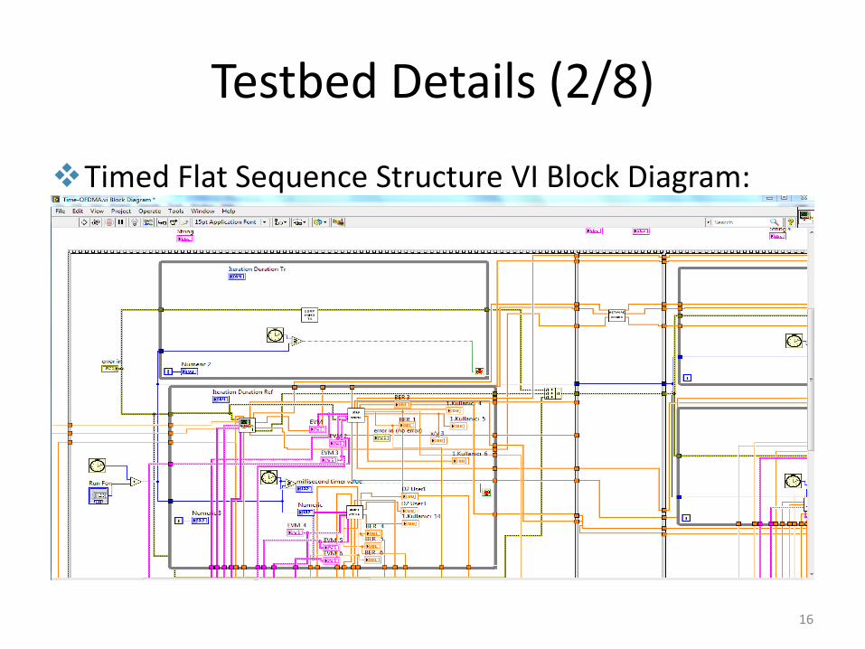
Testbed Details (2/8)
Timed Flat Sequence Structure VI Block Diagram:
16

Testbed Details (3/8)
Source node SubVI implementation structure:
17

Testbed Details (4/8)
Relay node SubVI implementation structure:
18

Testbed Details (5/8)
Destination node SubVI implementation structure:
19
Testbed Details (6/8)
Example of LabVIEW implementation:
-Relay SubVI’s transmitter code:
-RFSG VI
-Modulation Toolkit VI
-Signal Processing Library VI
-Array functions
20
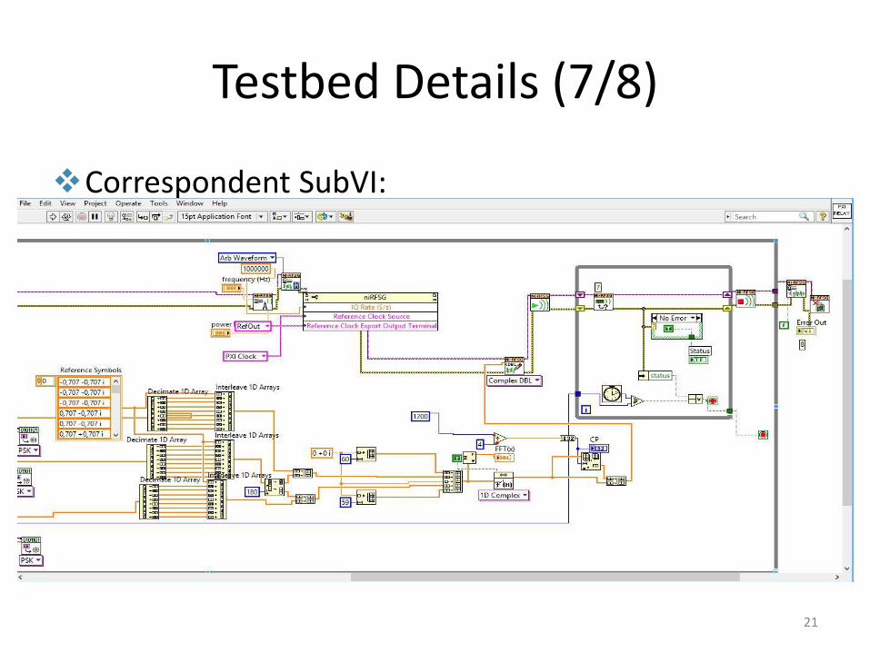
Testbed Details (7/8)
Correspondent SubVI:
21

Testbed Details (8/8)
Block diagram of relay network coding SubVI.
22

Test Parameters
• c
23
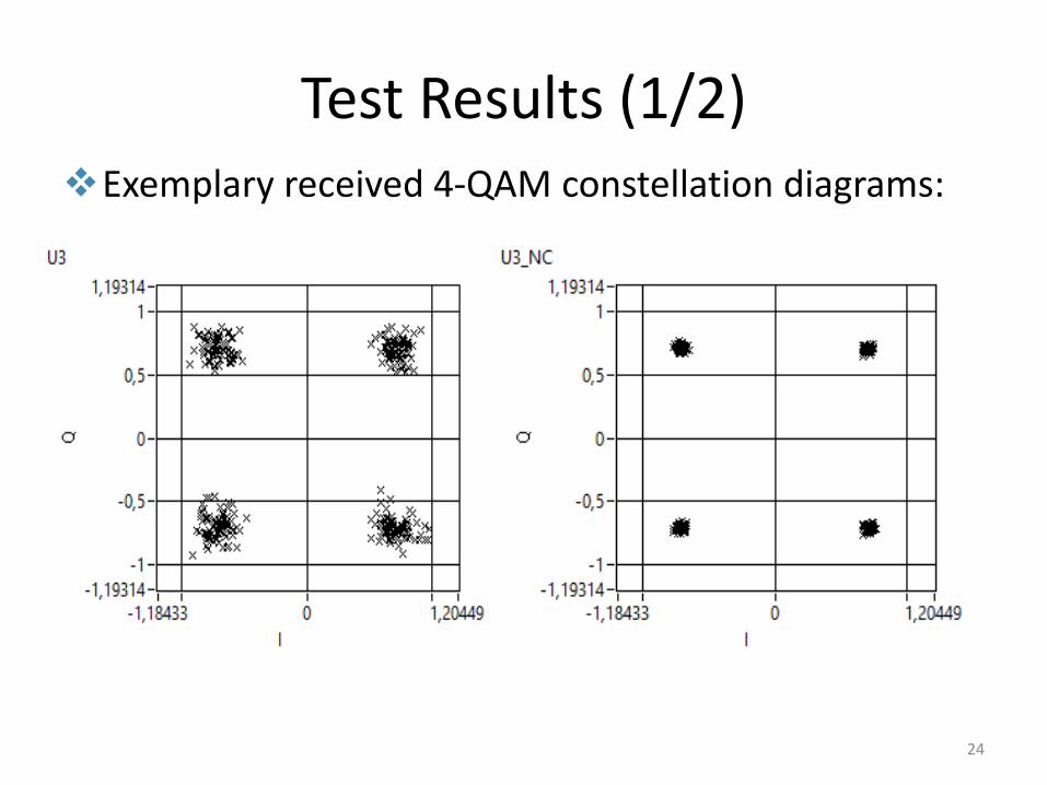
Test Results (1/2)Exemplary received 4-QAM constellation diagrams:
24

Test Results – Image Transmission
Image Transmission Implementation:
-Packet Transmission Algorithm:
-Dividing 100x100 pixel images to packets
-Index Portion: Shows packet’s index number, %5 of the frame length
-At Rx, by using index portion, packets are determined and put in right order to form image
25

Test Results – Image Transmission
26
without direct link
with direct link(NCC)
[11] S. Gökceli, S.Tedik Başaran, G.Karabulut Kurt, ‘A Testbed for Image Transmission over a Network Coded Cooperation System’, under review, VTC Fall 2016
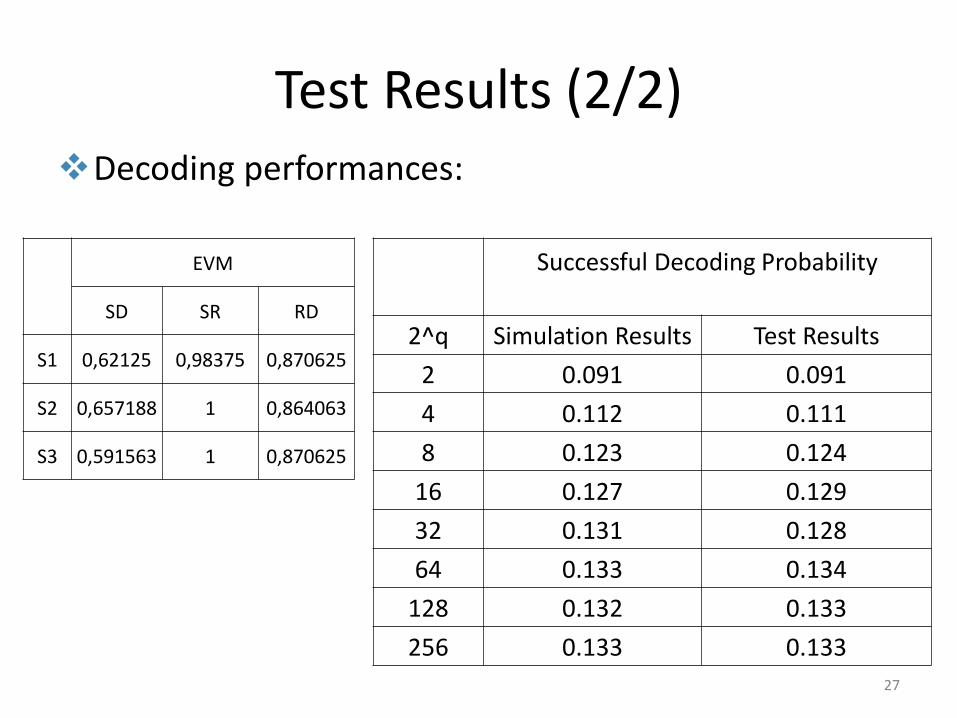
Test Results (2/2)Decoding performances:
Successful Decoding Probability
2^q Simulation Results Test Results
2 0.091 0.091
4 0.112 0.111
8 0.123 0.124
16 0.127 0.129
32 0.131 0.128
64 0.133 0.134
128 0.132 0.133
256 0.133 0.133
EVM
SD SR RD
S1 0,62125 0,98375 0,870625
S2 0,657188 1 0,864063
S3 0,591563 1 0,870625
27
Conclusions
• For practical applicability the impact of thewireless channel needs to be consideredCooperative network coding systems
– Non-zero error/erasure rates
– Direct source destination links
28

Thank you!
This work is supported by TUBITAK under Grant 113E294 & COST IC1104
29