a raspberry pi based autonomous car - biri.me · introduction most of us might be aware of the...
TRANSCRIPT

A Raspberry Pi based Autonomous Car
By William Mollenkopf
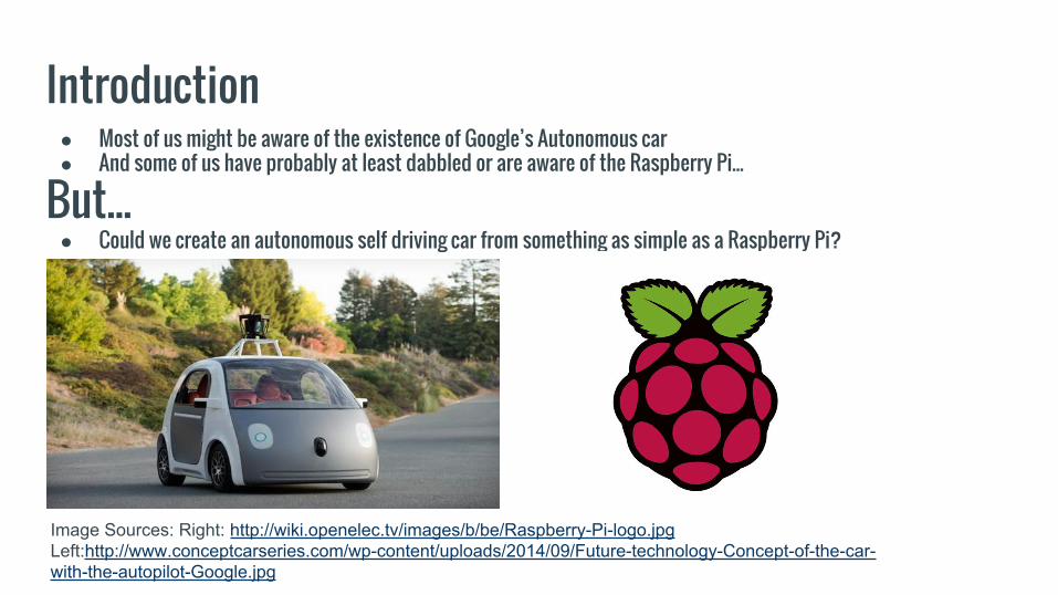
Introduction● Most of us might be aware of the existence of Google’s Autonomous car● And some of us have probably at least dabbled or are aware of the Raspberry Pi...
But... ● Could we create an autonomous self driving car from something as simple as a Raspberry Pi?
Image Sources: Right: http://wiki.openelec.tv/images/b/be/Raspberry-Pi-logo.jpgLeft:http://www.conceptcarseries.com/wp-content/uploads/2014/09/Future-technology-Concept-of-the-car-with-the-autopilot-Google.jpg

Requirements: Hardware● Raspberry Pi Model B Rev 2.● A Pi Camera for HD Photos● A USB Wi-Fi 802.11n adapter● Ultrasonic sensors● L293D Motor driver

Requirements: Software● Raspbian OS● The RPi.GPIO Python Library● OpenCV
○ Open Source Computer Vision library.○ Has over 2,500 optimized algorithms.○ Can be used for things such as: image processing, detection, facial recognition, object identification,
classification actions, traces, and other functions as well○ Used extensively by companies like Google, Yahoo, Microsoft, IBM, Intel, Sony, Honda, Toyota,
and many startup companies as well.○ Based on C++ but wrappers are available for Python (which is what they used for their project).○ Was used to help detect the roads and guide the car on unknown roads.

Hardware Implementation● The Raspberry Pi with attached Pi Camera and glued to the “top shelf”● The 4 wheels of the car are connected to 4 separate motors.
○ The motor drivers are capable of driving 2 motors simultaneously.○ The rotation of the wheels is synchronized on the basis of the sides
(ie: left front and left back rotate in sync)○ Thus, the the pair of motors on each side is given the
same digital input signal from the motor driver (L293D) at any given moment.
○ This helps the car move forward or backward,and can even make turns.

The Car

Lane Detection MethodologyFeature, and model based techniques are the two traditional approaches to performing lane detection.
The Feature Based:● Localizes the lanes in the road images by combining the low-level features.
(Such as painted lines, or lane edges.)● Requires a well studied road having well-painted lines or strong lane edges or else it’ll fail.● Also, it has the disadvantage of not imposing any global constraints on the lane edge shapes and is
susceptible to occlusion or noise (of the image).

Lane Detection Methodology (Cont.)The Model-Based Technique:
● This technique uses just a few parameters to represent lanes.● This is assuming the shapes of the lanes can be presented by either straight line or parabolic curve.● In this way, the model-based technique is much more robust against noise and missing data compared to the
feature-based technique.● To estimate the parameters of lane model, the likelihood function, Hough transform, and the chi-square fitting, etc.
Are all applied into lane detection

Lane Detection Methodology (Cont.)Problem & Solution:
● However, with most lane models, it is only focused on certain shapes of the road, and thus lack the flexibility to model an arbitrary shape of the road.
● In their proposed algorithm to detect the lanes, a combination of the feature based and the model based techniques were used.
● This algorithm is valid for all kinds of roads even if they’re marked with white lanes or not.

The Main Algorithm (Part 1 / 7)● Extract the appropriate upper and lower color range.● This is the most important part of the algorithm.● Using this range, a binary image of the current view is created.

The Main Algorithm (Part 2 / 7)Define the region of interest:● The region of interest is defined starting from the bottom, up.
○ Because the road surface is the closest to the car and it’s camera from the bottom, upwards (in terms of image height)
● The height of the region of interest is usually not more than half of the height of the image itself.● As we move away from the car, the width of the road narrows and forms a trapezium.

The Main Algorithm (Part 3 / 7)Convert complex region of interest into a simple shape● This is another important step in determining the boundary of the road.● In the region of interest, the contours are determined.● Since the car is on the road, the largest contour which contains the central part of the bottom region is the road.● This part of the algorithm simplifies the shape of the contour using approximations.

The Main Algorithm (Part 4 / 7)Determine the Shape of the Road● Hough lines are drawn on the manipulated contour.● A number of Hough lines are obtained along the left and right edges of the road
○ Out of these only a few lines represent the actual edge.● The rest of the lines are due to the noise along the edge - which are due to irregularities in the road.

The Main Algorithm (Part 5 / 7)Filter out the noise● The lines along the left edge of the road are tilted towards the right and vice versa.● This is so that any line which is titled towards the left and lies entirely on the left half of the image is discarded.
○ Same for the right side as well.● For the left edge, a line with the smallest angle or having the least positive x-intercept or y-intercept is chosen as
the left edge of the road.● Same for the right edge of the road.

The Main Algorithm (Part 6 / 7)Make it robust and unaffected from noise● In a moving car the change in the direction of the road isn’t something that’s abrupt.● Turns are usually nice, discrete, smooth turns.● So, any line which is far away from the line in a previous frame is simply discarded.● Another factor called tolerance is also considered.● Basically it is the count of continuous frames which could be accepted without without being able to determine
the edge of the road.● Its maximum value is 3, and if it’s not able to determine an edge, this counter decrements in value.● If that value reaches 0, another attempt is made to find the new color range of the road at the run time.

The Main Algorithm (Part 7 / 7)Determine the turns in the road, if any, and give directions to the car● Different cases of the road are considered, such as: left turn, right turn, divergence, roundabout, etc● Suppose there is a left turn as shown here (figure 6)● Divide the region of interest into three parts in the ratio of 2:3:5

The Main Algorithm (Part 7 / 7) (Cont.)Determine the turns in the road, if any, and give directions to the car● Depending on the continuation or break of the same line in the three different sections,
the final Range of Interest is modified which further assists to decide the turn present on the road.● The next challenge lies in determining the turns and changing the line of the motion of the car.● A temporary line shown in figure 7 overlapping the top edge of the ROI from left to right is drawn.● A tangent to the contour is also drawn at the intersection point of the temporary line with the contour.● If the intersection point lies outside the Range of Interest, the Range of Interest is modified to accommodate this
point within itself.
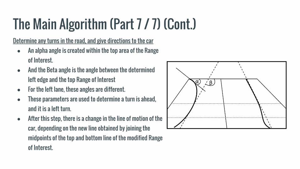
The Main Algorithm (Part 7 / 7) (Cont.)Determine any turns in the road, and give directions to the car● An alpha angle is created within the top area of the Range
of Interest.● And the Beta angle is the angle between the determined
left edge and the top Range of Interest● For the left lane, these angles are different.● These parameters are used to determine a turn is ahead,
and it is a left turn.● After this step, there is a change in the line of motion of the
car, depending on the new line obtained by joining the midpoints of the top and bottom line of the modified Range of Interest.

Development And Implementation Phases (Phase 1)Remote Controlled Car● Testing the controls manually.● Decided to go with an Android App● Communicates with open channel TTL● TTL set to high to keep the channel
open as long as possible.

Development And Implementation Phases (Phase 2)Phase 2: Obstacle Avoidance● Ultrasonic sensors are used to detect the distance of nearby flat objects.● Works by transmitting a low frequency sound from the sensor to the object which after reflection is
received by the receiver of the sensor.● The algorithm checks every 300ms and performs these 3 steps:1. Watches the surroundings to calculate the distance of objects from the car.
○ The minimum threshold that is safe for the car is 1 meter.2. If the distance is less than that:
1. The car stops and checks other sides,2. Then, it “rotates itself” around the obstacle.
3. Finally the car moves forward and will repeat this again.

Development And Implementation Phases (Phase 3)Phase 3: Car with autonomous navigation● This phase is about making the car autonomous.● The following images are also their results.

Development And Implementation Phases (Phase 3 Cont.)

(End): Main Sources● Gurjashan Singh Pannu, Mohammad Dawud Ansari, Pritha Gupta. "Design and
Implementation of Autonomous Car using Raspberry Pi" in International Journal of Computer Applications Vol.113-No. 9 (March 2015) <http://research.ijcaonline.org/volume113/number9/pxc3901789.pdf>
● Narayan Pandharinath Pawar, Minakshee M.Patil. "Driver Assistance System based on Raspberry Pi" in International Journal of Computer Applications Vol.95-No. 16 (June 2014) <http://research.ijcaonline.org/volume95/number16/pxc3896794.pdf>
● Raspberry Pi Foundation. “GPIO: Raspberry Pi Models A and B” <https://www.raspberrypi.org/documentation/usage/gpio/>
● Python Software Foundation. “RPi.GPIO 0.5.11 : Python Package Index” <https://pypi.python.org/pypi/RPi.GPIO>
● Wikipedia. “Hough transform” <https://en.wikipedia.org/wiki/Hough_transform>
● Wikipedia. “Ultrasonic transducer” <https://en.wikipedia.org/wiki/Ultrasonic_transducer>

(End): Image Sources● Gurjashan Singh Pannu, Mohammad Dawud Ansari, Pritha Gupta. "Design and
Implementation of Autonomous Car using Raspberry Pi" in International Journal of Computer Applications Vol.113-No. 9 (March 2015) <http://research.ijcaonline.org/volume113/number9/pxc3901789.pdf>
● Narayan Pandharinath Pawar, Minakshee M.Patil. "Driver Assistance System based on Raspberry Pi" in International Journal of Computer Applications Vol.95-No. 16 (June 2014) <http://research.ijcaonline.org/volume95/number16/pxc3896794.pdf>
● OpenELEC. “Welcome to the OpenELEC WIKI”<http://wiki.openelec.tv/images/b/be/Raspberry-Pi-logo.jpg>
● Concept Car Series. “Concept Car Series | Amazing Concept Cars & The Final Products” <http://www.conceptcarseries.com/wp-content/uploads/2014/09/Future-technology-Concept-of-the-car-with-the-autopilot-Google.jpg>
● Awesomer Media. “Cool Gadgets, Gizmos, Games and Geek Stuff” <http://technabob.com/blog/wp-content/uploads/2014/11/raspberry-pi-car-computer-by-harrison-kinsley.jpg>

(End): Questions?