a rayleigh-ritz analysis methodology for ......method to develop a stress analysis for finite...
TRANSCRIPT
N 9 3 - $ 0 8:6-9 . -A RAYLEIGH-RITZ ANALYSIS METHODOLOGY
FOR CUTOUTS IN COMPOSITE STRUCTURES I ,7//
Steven G. Russell
Northrop Corporation
Aircraft Division
Department 3853/82
One Northrop Avenue
Hawthorne, California
ABSTRACT
This paper describes a new Rayleigh-Ritz stress analysis methodology that
has been developed for composite panels containing cutouts. The procedure, which
makes use of a general assumed displacement field, accommodates circular and ellipti-
cal cutouts in biaxially loaded rectangular composite panels. Symmetric integral
padups around the cutout can be included in the analysis. Benchmark results are
presented to demonstrate the accuracy of the technique, and strength predictions
based on the average stress criterion are generated and compared with experimental
data. Finally, the stress analysis methodology is integrated into a design procedure
for sizing integral padups around circular cutouts, and a sample problem is solved to
illustrate its use.
INTRODUCTION
Cutouts of various shapes and sizes occur at numerous locations in typical
aircraft structures. These cutouts range in complexity from simple holes designed to
accommodate fasteners in bolted wing splices to large, reinforced openings that
provide systems routing and access in major fuselage bulkheads. The design of these
details in composite structures requires an accurate stress analysis technique and a
realistic criterion to predict structural failure.
The analysis of cutouts in orthotropic and anisotropic materials has been
the focus of numerous research efforts over the years. Both analytical and numerical
methods have been developed for a variety of cutouts under different loading condi-
tions. Many of the analytical methods are based upon the use of complex stress
functions from the theory of elasticity. Lekhnitskii (Reference i) developed analy-
ses for elliptical, triangular, oval, and square cutouts in infinite anisotropic
plates under in-plane loading. DeJong (Reference 2) extended this body of work in an
analysis of rectangular cutouts with rounded corners in infinite orthotropic plates.
i This work was performed under NASA/Northrop Contract NASI-18842, entitled "Innova-
tive Composite Fuselage Structures."
901
https://ntrs.nasa.gov/search.jsp?R=19930021680 2020-06-19T18:08:14+00:00Z

Recently, Prasad and Shuart (Reference 3) developed a general, closed form solution
for the moment distribution in infinite anisotropic plates containing circular or
elliptical holes and subjected to applied bending moments.
Numerical procedures such as finite element, boundary element, and boundary
collocation analysis have been widely used to provide stress analysis of finite
plates with cutouts. Hong and Crews (Reference 4) used the finite element method to
calculate stress concentration factors around circular holes in uniaxially loaded
finite orthotropic plates. The SY5 computer program (Reference 5) uses the finite
element method to provide stress analysis for finite isotropic or orthotropic plates
with circular, elliptical, square, oval, or rectangular cutouts. Generalized in-
plane loading conditions can be accommodated, and padups around cutouts can be mod-
eled using the first three rows of elements around the cutout. The CREPAIR computer
program (Reference 6) can be used to analyze elliptical, slotted, and rectangular
cutouts in finite orthotropic plates by the boundary element method. CREPAIR is
restricted to problems involving biaxial tension/compression or in-plane shear load-
ing conditions. The SASCJ computer code (Reference 7) uses the boundary collocation
method to provide stress analysis for loaded fastener holes in finite orthotropic
plates. Recently, Klang and Owen (Reference 8) have used the boundary collocation
method to develop a stress analysis for finite anisotropic panels containing circular
or elliptical cutouts and subjected to in-plane shear loading conditions.
Despite the substantial body of work devoted to stress analysis of
orthotropic and anisotropic plates with cutouts, several deficiencies remain in the
overall analysis capability. The analytical methods, which are often well-suited for
repeated design calculations, are usually valid only for infinite plates. The finite
element method requires elaborate preprocessing and postprocessing routines to pro-
vide specialized results for cutout problems. The boundary element and boundary
collocation approaches, which are especially useful for cutouts with irregular
shapes, are difficult to extend to problems involving reinforced cutouts. This paper
describes a new approach to cutout stress analysis that is being developed to over-
come some of these limitations.
The cutout analysis methodology documented in this paper is based on the
Rayleigh-Ritz structural analysis technique, and it makes use of a general assumed
displacement field that can be used to treat a wide variety of cutout problems in
finite orthotropic plates. This approach eliminates elaborate preprocessing and
postprocessing requirements, allows for direct calculation of stress concentration
factors at the edge of the cutout, and easily accommodates padups and reinforcements
around the hole. As presented here, the methodology is applicable to circular and
elliptical cutouts in biaxially loaded orthotropic plates, but it can be extended to
include other configurations and loading conditions.
The following sections of the paper provide a description of the Rayleigh o
Ritz analysis methodology and a presentation of benchmark results to demonstrate the
accuracy of the approach. Next, the analysis methodology is correlated with experi-
mental results and used to generate strength predictions for composite tension speci-
mens with open circular holes. Finally, a design procedure and sample problem are
presented to show how the analysis methodology can be used in the design of integral
padups around circular cutouts. A complete listing of the equations that are re-
quired to implement the cutout analysis methodology is provided in the Appendix.
902

ANALYSIS METHODOLOGY
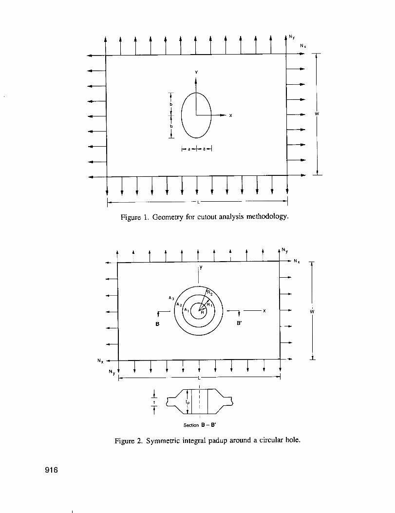
Consider an elliptical cutout in a biaxially loaded composite panel as shown
in Figure i. The panel is modeled as a thin, elastic orthotropic plate under in-
plane loading. Due to the symmetry of the cutout geometry and loading, the analysis
is confined to the first quadrant x,y > 0 of a rectangular coordinate system with
origin at the center of the cutout. Polar coordinates r,9 are defined with respect
to the rectangular coordinates x,y by the usual transformation relations r -
(x2+y2) _, 0 = tan-l(y/x).
The principle of virtual work for the loaded panel can be expressed as
IA 6I_}T{NIdA " I 6{u}Tlt}dS = 0S
(i)
where,
{u} = vector of panel displacements
{N} = vector of panel stress resultants
{e} - vector of strains at the panel middle surface
{t) = vector of surface tractions applied along the panel boundary
In Equation i, A is the panel area and S is the curve that defines the panel bounda-
ry. The symbol, 6, represents an arbitrary variation of a quantity consistent with
the displacement boundary conditions, which require vanishing normal displacements
along the axes of symmetry.
Stress analysis of the panel can be carried out using the Rayleigh-Ritz
method. In this procedure, an assumed displacement field containing unknown parame-
ters is developed for the panel and substituted into the principle of virtual work,
Equation I, to yield equations for determination of the unknown parameters. The
stress analysis of circular or elliptical cutouts in biaxially loaded panels is based
upon the assumed displacement field
Ur i
N M k
y. y. qj fk(r)cos2j #j-O k=l
(2)
N M M+k
u 0 = E Z qj fk(r)sin2j0j=O k-1
k
where Ur, u0 are polar coordinate displacement components and qj are unknown parame-ters. (NOTE that k is used here as a superscript.) The functions fk(r) are given by
fk(r) = r2(k-M)+l for k = 1,...,M (3)
where the superscripted quantity is an exponent. The displacement field of Equation
2 satisfies the symmetry conditions, which require vanishing normal displacement and
903

shear stress along the x and y axes in Figure I. The parameters M and N in Equation
2 can be adjusted to give the required number of series terms necessary for accurate
solution of the problem. Substitution of Equations 2 and 3 into the principle of
virtual work leads to a system of linear algebraic equations of the form
[K]{q} = {T} (4)
where
[K] = stiffness matrix
{q} = vector of unknown coefficients
{T} = load vector
Details of the derivation of Equation 4 and the subsequent calculation of panel
stresses and strains are given in the Appendix.
The foregoing analysis procedure can be extended to account for the presence
of symmetric integral padups around the cutout. Consider an integral padup around a
circular cutout as shown in Figure 2. The reinforced region, AI, has thickness tp
and the unreinforced region, A3, has thickness t. These two constant thickness
regions are joined by a tapered region, A2, where the thickness varies linearly withthe radial coordinate. The stiffness matrix [K] for the reinforced panel is calcu-
lated by carrying out the integration over the panel area, A, in three parts for
regions AI, A2, and A3, respectively. In Region A2, a linear variation of the
extensional stiffness is assumed. Hence,
(I) (r-Rl) (3)(2) (r-R2) Ajk + Ajk (5)
AJ k (RIoR2) (R2oR I)
(i)
where, RI, R2 are defined in Figure 2, Ajk are the extensional stiffness for regioni, and j,k = 1,2, or 6. The general procedure given in the Appendix for calculation
of the unreinforced panel stiffness matrix can be used for the reinforced panel as
well.
BENCHMARK RESULTS
The analysis methodology discussed in the previous section was implemented
in a FORTRAN computer program, and benchmark results were generated to test its
accuracy relative to well-established cutout stress analysis techniques. Figure 3
shows a comparison of results for the stress concentration factor at a circular hole
in a uniaxially loaded rectangular plate. Rayleigh-Ritz analysis results were checked
against results generated using the anisotropic finite width correction factors
developed by Tan (Reference 9). Both (25/50/25) quasi-isotropic (i.e., 25% 0 °, 50%
±45 ° , and 25% 90 ° plies) and (50/39/11) orthotropic laminates were considered. For
both types of laminates, very good agreement was obtained for a wide range of hole
diameter/plate width ratios. The Rayleigh-Ritz results shown in Figure 3 were gener-
ated by taking N=5, M=6 in the assumed displacement field given in Equation 2.
904
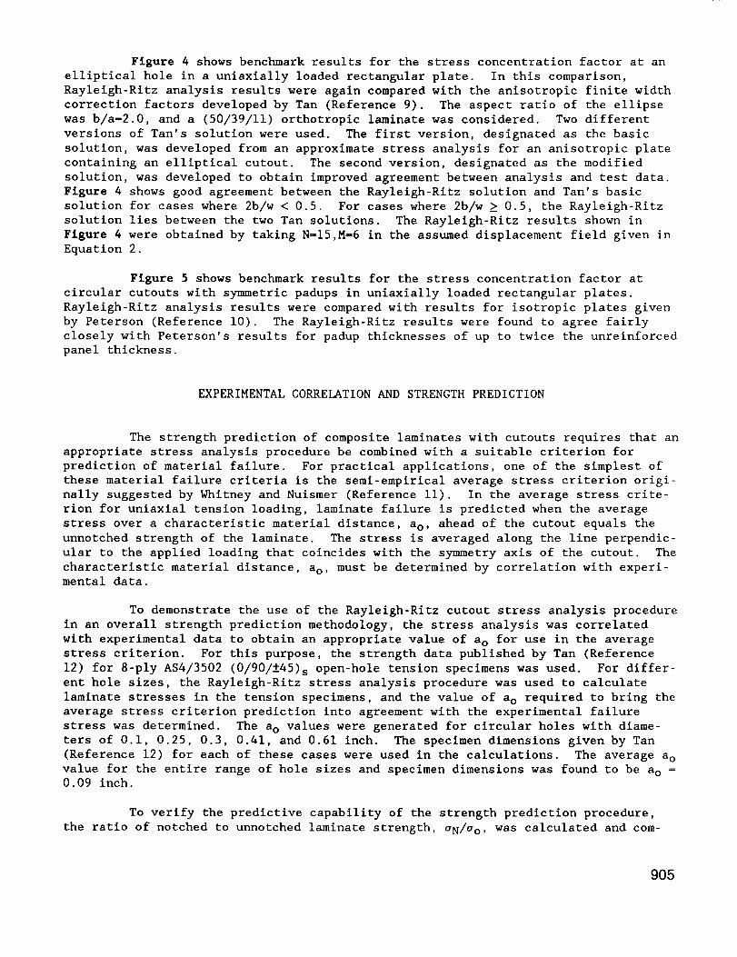
Figure 4 shows benchmark results for the stress concentration factor at an
elliptical hole in a unlaxially loaded rectangular plate. In this comparison,
Rayleigh-Ritz analysis results were again compared with the anisotropic finite width
correction factors developed by Tan (Reference 9). The aspect ratio of the ellipse
was b/a_2.0, and a (50/39/11) orthotropic laminate was considered. Two different
versions of Tan's solution were used. The first version, designated as the basic
solution, was developed from an approximate stress analysis for an anisotropic plate
containing an elliptical cutout. The second version, designated as the modified
solution, was developed to obtain improved agreement between analysis and test data.
Figure 4 shows good agreement between the Rayleigh-Ritz solution and Tan's basic
solution for cases where 2b/w < 0.5. For cases where 2b/w _ 0.5, the Rayleigh-Ritz
solution lies between the two Tan solutions. The Rayleigh-Ritz results shown in
Figure 4 were obtained by taking N=I5,M-6 in the assumed displacement field given in
Equation 2.
Figure 5 shows benchmark results for the stress concentration factor at
circular cutouts with symmetric padups in uniaxially loaded rectangular plates.
Rayleigh-Ritz analysis results were compared with results for isotropic plates given
by Peterson (Reference i0). The Rayleigh-Ritz results were found to agree fairly
closely with Peterson's results for padup thicknesses of up to twice the unreinforced
panel thickness.
EXPERIMENTAL CORRELATION AND STRENGTH PREDICTION
The strength prediction of composite laminates with cutouts requires that an
appropriate stress analysis procedure be combined with a suitable criterion for
prediction of material failure. For practical applications, one of the simplest of
these material failure criteria is the semi-empirical average stress criterion origi-
nally suggested by Whitney and Nuismer (Reference ii). In the average stress crite-
rion for uniaxial tension loading, laminate failure is predicted when the average
stress over a characteristic material distance, ao, ahead of the cutout equals the
unnotched strength of the laminate. The stress is averaged along the line perpendic-
ular to the applied loading that coincides with the symmetry axis of the cutout. The
characteristic material distance, ao, must be determined by correlation with experi-mental data.
To demonstrate the use of the Rayleigh-Ritz cutout stress analysis procedure
in an overall strength prediction methodology, the stress analysis was correlated
with experimental data to obtain an appropriate value of ao for use in the average
stress criterion. For this purpose, the strength data published by Tan (Reference
12) for 8-ply AS4/3502 (0/90/±45)s open-hole tension specimens was used. For differ-
ent hole sizes, the Rayleigh-Ritz stress analysis procedure was used to calculate
laminate stresses in the tension specimens, and the value of a o required to bring the
average stress criterion prediction into agreement with the experimental failure
stress was determined. The a o values were generated for circular holes with diame-
ters of 0.i, 0.25, 0.3, 0.41, and 0.61 inch. The specimen dimensions given by Tan
(Reference 12) for each of these cases were used in the calculations. The average a o
value for the entire range of hole sizes and specimen dimensions was found to be a o =
0.09 inch.
To verify the predictive capability of the strength prediction procedure,
the ratio of notched to unnotched laminate strength, aN/ao, was calculated and com-
9O5
pared with experimental data published by Nuismer and Whitney (Reference 13). The
value ao-0.09 inch was used in the calculations, which were carried out for 16-ply
T300/5208 laminates with (0/±45/90)2s and (0/90)4s layups and nominal hole diameters
of 0.I, 0.3, 0.6, and 1.0 inch. The specimen dimensions given by Nuismer and Whitney
(Reference 13) were used in each of the eight analytical predictions. Figure 6 shows
a comparison between the analytical predictions and experimental data as a function
of hole diameter. For the quasi-isotropic (0/±45/90)2s laminate, the predictions
were i0 to 20 percent conservative for the range of hole sizes considered. The
predictions for the orthotropic (0/90)4s laminate were approximately 20 to 30 percent
conservative. A plot of predicted versus measured values of aN/a o for the eight test
cases is shown in Figure 7.
Based upon the limited number of data considered, the analytical strength
prediction procedure for open hole tension specimens seems to provide a conservative
estimate of the specimen notched strength. Improved agreement between analysis and
experiment can be obtained by adopting a more sophisticated form of the average
stress criterion in which the parameter, ao, is adjusted for different layups and
hole sizes. At the time of this writing, experimental correlation and verification
of this semi-empirical strength prediction procedure was continuing.
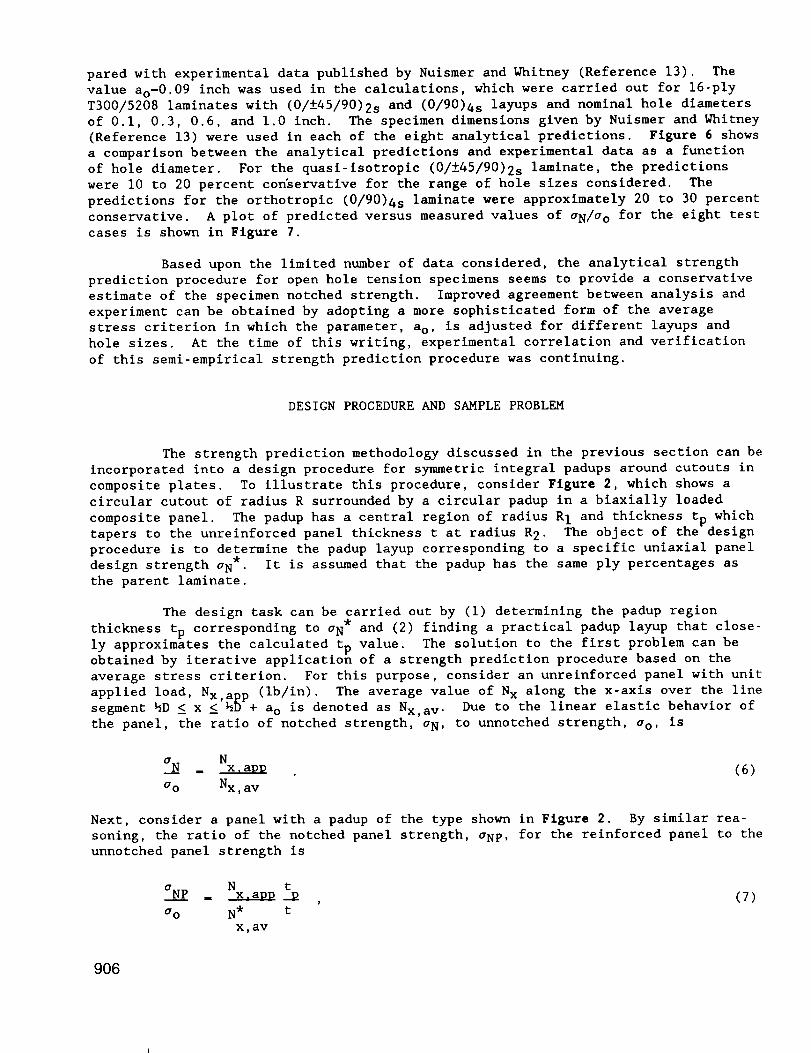
DESIGN PROCEDURE AND SAMPLE PROBLEM
The strength prediction methodology discussed in the previous section can be
incorporated into a design procedure for symmetric integral padups around cutouts in
composite plates. To illustrate this procedure, consider Figure 2, which shows a
circular cutout of radius R surrounded by a circular padup in a biaxially loaded
composite panel. The padup has a central region of radius RI and thickness tp which
tapers to the unreinforced panel thickness t at radius R 2. The object of the design
procedure is to determine the padup layup corresponding to a specific uniaxial panel
design strength aN*. It is assumed that the padup has the same ply percentages as
the parent laminate.
The design task can be carried out by (I) determining the padup region
thickness tp corresponding to aN* and (2) finding a practical padup layup that close-
ly approximates the calculated tp value. The solution to the first problem can be
obtained by iterative application of a strength prediction procedure based on the
average stress criterion. For this purpose, consider an unreinforced panel with unit
applied load, Nx,ap p (ib/in). The average value of N x along the x-axis over the line
segment hD _ x _ hD + a o is denoted as Nx,av. Due to the linear elastic behavior of
the panel, the ratio of notched strength, aN, to unnotched strength, a o, is
a N = N__ x.amm (6)
ao Nx,av
Next, consider a panel with a padup of the type shown in Figure 2. By similar rea-
soning, the ratio of the notched panel strength, aNp, for the reinforced panel to the
unnotched panel strength is
aNp - N t-- _ -_ , (7)
ao N* t
x,av
906

where N* is the average stress along the x-axis over the line segment hD _ x <, x,av
_D+a o. The * superscript indicates that the average stress resultant N*x,av is
computed in the reinforced region that has thickness tp. Since the value of tp
influences the operall load transfer into the padup region from the unreinforced
portion of the panel, N*x,av is a complicated function of tp.
In the design problem, the desired value of tp corresponds to the case whereaNp - a* N. For this case, combination of Equations 6 and 7 gives
N* (t) * tx_av p a__N . ___ z 0
Nx,av a N t
(8)
Equation 8 must be solved iteratively to determine the padup region thickness, t_.
For this purpose, a design function, g(tp), equal to the left-hand side of Equatlon 8
is introduced. Using two initial estimates for tp, the secant method can be used to
find tp such that g(tp) < 6, where 6 is a sufficiently small number.
After the padup thickness, tp, corresponding to o* N has been determined, it
remains to find a practical padup layup with the same percentage of plies as the
parent laminate. For the case of symmetric integral padups, material of thickness,
(t -t)/2, must be added to each side of the panel. Therefore the practical padupplayup for each side of the panel is the least number of plies that (i) maintains ply
percentages of the parent laminate and (2) has total thickness of at least (tp-t)/2.
A flowchart for the padup design procedure is shown in Figure 8. To
illustrate the use of this procedure, consider a sample problem involving the panel
geometry shown in Figure 2. The parent laminate is a 36-ply (25/50/25) AS4/3502
panel. The geometrical parameters are L-10 inches, Wz4 inches, R=0.5 inch, RI=0.75
inch, R2=I inch, and t=0.1872 inch. The unnotched panel strength is ao=71.7 ksi and
the panel design strength is a'N-40 ksi. A value ao-0.09 inch is assumed for the
average stress criterion.
For the unreinforced panel with cutout radius R=O.5 inch, the notched panel
strength ON= 27.1 ksi. Therefore, a padup is necessary if the panel is to withstand
the design strength O'N=40 ksi. Using the iterative procedure illustrated in Figure
8 with initial thickness estimates of tp=t and tp=l.lt, the necessary value of tp was
found to be tp_0.2996 inch. The practical padup-corresponding to this value of tp
has 12 plies (three 0 °, six ±45 ° , three 90 ° ) of material on each side of the panel.
For the practical padup, tp-0.312 inch. A strength analysis for this value
of tp gives a reinforced notched panel strength of aNp-41.4 ksi. Since this value of
aNp gives a positive margin of safety with respect to the design strength a'N-40 ksi,
the padup design procedure has achieved its purpose.
SUMMARY AND FUTURE PLANS
In the previous sections, a Rayleigh-Ritz stress analysis methodology for
composite panels with cutouts has been described, and its applications to panel
strength prediction and design of symmetric integral padups around cutouts have been
illustrated. In its current state of development, this methodology can be applied to
907
circular or elliptical cutouts in rectangular panels under biaxial tension/ compres-
sion loading. The advantages of the procedure are its ability to provide accurate
numerical stress analysis solutions with a minimum of input data, and its capability
to accommodate cutout reinforcements, such as padups. Its disadvantage is its re-
stricted applicability, which currently includes only a limited number of cutout
geometries and panel loading conditions.
Future development efforts for the Rayleigh-Ritz cutout stress analysis
methodology will be focused on the incorporation of substructural effects into the
analysis, and the extension of the procedure to more complex cutout geometries and
loading conditions. The effect of integral stiffeners can be included in the analy-
sis by assuming strain compatibility between the stiffeners and the panel. The
strain in the stiffeners can then be calculated using the assumed displacement field
given in Equations 2 and 3, and virtual strain energy terms for the stiffener ele-
ments can be added to the left-hand side of Equation i. By this approach, the effect
of any number of stiffener elements can be included in the analysis without increas-
ing the number of degrees of freedom in the solution process. An effort to implement
the substructural effects analysis for the common case of a "picture-frame" stiffen-
ing arrangement around a cutout is currently underway.
Future analysis efforts will also include attempts to extend the existing
methodology to include more complex cutout shapes and loading conditions. The analy-
sis of complex cutout shapes, such as slotted holes and rectangles with rounded
corners, will require some modification of the basic analysis procedure presented
here. One promising approach that will be investigated is use of the penalty func-
tion method (Reference 14) in conjunction with the assumed displacement field of
Equations 2 and 3. This approach, which involves constructing penalty functions from
specified constraint conditions, will make it possible to closely satisfy stress-free
boundary conditions along the cutout perimeter without introducing additional degrees
of freedom. Further modifications will be required to enable the stress analysis
procedure to accommodate more complex loading conditions. For in-plane shear load-
ing, a different assumed displacement field will be constructed to exploit symmetries
in the deformation of the panel under this type of loading. This displacement field
will be implemented into the analysis using the procedures illustrated in the Appen-
dix. Stress analysis results for problems involving generalized in-plane loading can
then be obtained by superposing results obtained from the separate analyses for
biaxial and shear loading.
In future work, a concurrent approach to the development of design
procedures and enhanced stress analysis methodologies will be pursued. The initial
portion of this work, which consists of a design procedure for symmetric integral
padups around circular holes in uniaxially loaded panels, was illustrated in this
paper. A generalization of this design procedure to permit sizing of cutout rein-
forcements and stiffening elements will be developed as the extensions to the stress
analysis methodology are completed.
REFERENCES
i. Lekhnitskii, S.G., Anisotropic Plates, Second Edition, translated from Russian
by S.W. Tsai and T. Cheron, Gordon and Breach Science Publishers, 1968.
908

.
.
.
.
.
°
.
.
I0.
ii.
121
13.
14.
DeJong, Theo, "Stresses Around Rectangular Holes in Orthotropic Plates," Journal
of Composite Materials, Volume 15, 1981, pp 311-328.
Prasad, C.B. and Shuart, M.J., "Moment Distributions Around Holes in Symmetric
Composite Laminates Subjected to Bending Moments," AIAA Journal, Volume 28,
1990, pp 877-882.
Hong, C.S. and Crews, J.H., Jr., "Stress Concentration Factors for Finite
Orthotropic Laminates With a Circular Hole and Uniaxial Loading," NASA TP-1469,
May 1979.
Eisenmann, J.R., "Stress Distribution Around Cutouts," General Dynamics, Convair
Aerospace Division, Report FZM-5555, August 1970.
Hinkle, T. and Hoehn, G., "Verification of Analytical Methodology for Designing
Repairs to Composite Skin, Volume I Theoretical Development and Test Correla-
tions," McDonnell Aircraft Company, AFWAL-TR-87-3049, Volume I, October 1987.
Ramkumar, R.L., Saether, E.So, and Cheng, D., "Design Guide for Bolted Joints in
Composite Structures," Northrop Corporation, AFWAL-TR-85-3064, August 1985.
Klang, E.C. and Owen, V.L., "Shear Buckling of Specially Orthotropic Plate With
Centrally Located Cutouts," Proceedings of the Eighth DoD/NASA/FAA Conference on
Fibrous Composites in Structural Design, November 1989.
Tan, S.C., "Finite-Width Correction Factors for Anisotropic Plate Containing a
Central Opening," Journal of Composite Materials, Volume 22, 1988, pp 1080-1097.
Peterson, R.E., Stress Concentration Factors, John Wiley and Sons, New York,1974.
Whitney, J.M. and Nuismer, R.J., "Stress Fracture Criteria for Laminated
Composites Containing Stress Concentrations," Journal of Composite Materials,
Volume 8, 1974, pp 253-265.
Tan, S.C., "Laminated Composites Containing an Elliptical Opening II.
Experiment and Model Modification," Journal of Composite Materials, Volume 21,
1987, pp 949-968.
Nuismer, R.J. and Whitney, J.M., "Unlaxial Failure of Composite Laminates
Containing Stress Concentrations," Fracture Mechanics of Composites, ASTM STP
593, American Society for Testing and Materials, 1975, pp 117-142.
Cook, R.D., Concepts and Applications of Finite Element Analysis, Second
Edition, John Wiley and Sons, New York, 1981.
909

APPENDIX
For problem solution, it is convenient to represent the assumed panel
displacements given in Equation 2 in the matrix form
ur } N(u} - - _ [U_]{qj}u0 j=O J
(A-t)
where {qj} is a vector of dimension 2M containing unknown parameters and [Uj] is a2 x 2M matrix of the form
[Uj] _ [ flcos2j0 fMcos2J8 0 ...... 0 ]0 ..... 0 flsin2J 0 fMs in2j #
(A-2)
The strain vector {_} is obtained by applying the strain-displacement, relations forpolar coordinates:
I'r}7r8
a__ 0ar
1 i___r r @6
!&_ i__lr a9 ar r
{u} (A-3)
Substitution of Equations A-I and A-2 into Equation A-3 leads to a relation of theform
N
{_} m Z [H{](q{ } (A-4)j-O
where [Hj] is a 3 x 2M matrix whose entries are given by
f'cos2j8 for m - I ..... MHj,I m _ m (A-5)
0 for m - M+I .... 2M
ifmcos2j8 for m - I ..... MHj, 2m - r (A- 6)2j!fm_MCOS2 j 0 for m - M+I .... 2M
r
-2j ifmsin2j8 for m- I ..... MHj, 3m - r (A-7)(f' 1fro)sin2 j 0 for m - M+I .... 2M
m r
The superposed prime denotes differentiation with respect to r. The stress resultant
vector (N} is obtained by application of the stress-strain relations. Let Ex, Ey,Gxy, Vxy be the orthotropic elastic constants for the panel. Let
910

-- E t v E tAll - X AI2 - xy y
I-VxyWy x I-VxyUy x
- E t -
A22 - Y A66 - GxytI-VxyWy x
where Vyx - Wxy(Ey/Ex) and t is the panel thickness.given by
{N} - N 0 -
Nr8
All AI2 AI6
AI2 A22 A26
AI6 A26 A66
I'r}c8
Vr8
where
(A-8)
The stress resultant vector is
(A-9)
All - illCOS48 + 2(A12 + 2A66)sln20cos20 + A22sin48
AI2 - (All + A22 4A66) sin28c°s2# + AI2( c°s40 + sin4#)
AI6 - -(All - AI2 - 2A66) sinSc°s30 (AI2 - A22 + 2A66) sinBgc°s0
A22 - Allsin48 + 2(A12 + 2A66)sin28cos20 + A22cos48
A26 - "(All " AI2 " 2A66) sin30c°s9 (AI2 " A22 + 2A66) sinSc°s39
A66 - (All + A22 2A12 2A66) sin28c°s29 + A66 (sin49 + c°s48)
(A-IO)
Equation A-9 can be written in the compact matrix form
{N} - [A]{_} (A-II)
where [A] is the 3 x 3 matrix in Equation A-9.
For the rectangular panel of length L and width W shown in Figure i, the r
coordinate defining the boundary is a function of 9 given by
I L for 0 <_ 8 <_
2cos9
(A-12)Rb(9) - _ for _ < 0 < -_
2sin0 - - 2
where 4 - tan-l(w/L). The r coordinate defining the edge of the elliptical cutout is
also a function of 8 given by
Rc($ ) ab (A-13)
(a2sin28 + b2cos28)h
911

where a,b are the dimensions of the ellipse semiaxes. The surface traction vector
along the panel boundary is
t8
I Nx(l+cos28 )tr =
i Ny(l-cos20)
for 0 < 8 <
for 4 < 8 < -_2
(A-14)
(A-15)
t8 = { xSin2'i Nysin28
for0_8_4
for4_8_2
(A-16)
Introducing Equations A-I, A-4, A-II, and A-14 into Equation i leads to a matrix
equation of the form
[K]{q} = (T} , (A-17)
where [K] is an M(2N+I) x M(2N+I) stiffness matrix, {q} is an M(2N+I) x i vector of
unknown displacement field parameters and {T} is an M(2N+I) x i load vector.
The stiffness matrix [K] can be represented in the partitioned form
[K]
[Ko0] [K01] [KON]
[KI0] [KII] [KIN]
[KN0] [KNI] [KNN]
(A-18)
where the partition [K00 ] is an M x M matrix, the partitions [K01 ]..... [KON ] are M x
2M matrices, the partitions [KI0 ] ..... [KN0 ] are 2M x M matrices, and the remaining
partitions are 2M x 2M matrices. The elements of a general partition [Kjk ] are given
by the relations
Kjk,m n = {[All_m n + Al2(6mn + 6nm) + A224mn]COS2jScos2k8
- 2k(A166nm + A264mn)COS2j0sin2k8
- 2j(A166mn + A264mn)Sin2jgcos2k8
+ 4jkA664mnSin2 j 9sin2k8 }d9
for I _< m _<M, 1 <_ n <_ M
(A-19)
912
where,
Kjk,mn -
Kjk, mn
Kj k, mn
_ [2k(A126n'M'm + A224m,n_M)Cos2j0eos2k0
+ (Al6Am,n_ M + A26_m,n_M)COS2j0sin2k8
- 4jkA264m,n.MSin2 j 8cos2k8
- 2jA66_m,n_Msin2j 8sin2k0 ]d_
for I _< m _< M, M+I _< n < 2M
- [2j(AI26m.M, n + A224m.M,n)COS2j0cos2kO
- 4jkA264m_M,nCOS2 j #sin2k0
+ (Al6_n,m. M + A26_n,m_M)sin2jScos2k8
2kA66_n, m_MSin2j 8sin2k8 ]d9
for M+I _< m < 2M , i < n _< M
- [4j kA22_m_M,n.MCos2j 0eos2k0
+ 2jA26_m_M,n_MCOS2 j 0sin2k8
+ 2kA26_n_ M,m_Msin2j 8cos2k8
+ A66_m.M,n_MSin2 j #sin2k8 ]d0
for M+I < m < 2M , M+I < n < 2M
b , ,/gmn = fmfnrdr
C
Rb6mn - fmfndr
R c
4mn " ifmfndrr
c
AmnRb , ,
- fm(fn - !fn)rdr
Rc r
_mn - 6nm
(A-20)
(A-21)
(A-22)
(A-23)
(A-24)
(A-25)
(A-26)
913
_mnRb
fm(fn - !fn)dr
Rc r
= 6mn " 4mn (A-27)
_mnRb ,
- (fm " !fm)dr
Rc r
- _mn " 6mn - 6nm + ¢mn (A-28)
for i _ m,n _ M. In Equations A-23 through A-31, the prime denotes differentiation
with respect to r. Using the functions defined in Equation 3, the integrals in
Equations A-23 through A-25 can be evaluated to obtain
_mn
2(m+n)-4M+2] [2(m+n)-4M+2] }[2(m-M)+l][2(n-M)+l] Ri__ - R c
[2(m+n) - 4M+2]
for m+n _ 2M-I ,
[2(m-M)+l][2(n-M)+l] In(Rb/R c)
for m+n - 2M-I
(A-29)
6m n z
2(m+n)-4M+2] [2(m+n)-4M+2] }[2(n-M)+l] Ri__ - R c
[2(m+n) 4M+2]
for m+n _ 2M-I ,
[2(n-M)+l]in(Rb/R c)
for m+n - 2M-I
(A-30)
_mn m
[2(m+n)-4M+2] [2(m+n)-4M+2] }I Rb Rc
[2(m+n) 4M+2]
in(Rb/R c)
for m+n _ 2M-I ,
for m+n - 2M-I
(A-31)
The quantities R b and R c are functions of 8 as defined in Equations A-12 and A-13.
The integrals in Equations A-19 through A-22 can be evaluated numerically using
Simpson's rule.
The load vector (T} in Equation A-17 can be represented in the partitioned
form
914

{T}
{To}
{T I }
{Tj )
{TN)
(A-32)
where {TO } is an M x 1 vector and the remaining partitions are 2M x i vectors•
elements of a general partition {Tj} are given by the relations
I NxL 140 fm(Rb)COS2jSd#Tj ,m - 2
The
+ ! NyW fm(Rb) cos2j 9d82
for m - I,...,M (A-33)
Tj ,m 1 NxL 140fm'M(Rb)sin2jStanSd82
+ ! NyW fm_M(Rb)sin2jScot0d82
for m - M+I ..... 2M (A-34)
These integrals can be evaluated numerically using Simpson's rule. Finally, the
vector of unknown displacement field parameters {q} in Equation A-17 can be written
in the partitioned form
(q}
{q0)
(ql)
{qj }
{qN }
(A-35)
where {qo} is an M x i vector and the remaining partitions are 2M xl vectors•
Solution of the system of linear algebraic equations represented by Equation
A-17 yields the vector of displacement field parameters {q}. Displacements, strains,
and stress resultants at any point in the cutout panel can be calculated by evaluat-
ing Equations A-l, A-4, and A-9, respectively•
915
IIT1111111TY
-fb
b
±_a--4--a-q
X
lllllllllllL =
Figure 1. Geometry for cutout analysis methodology.
Ny
Nx
W
.el-.---
N x .,,B.
Ny
T11;ITIITY
f-- --_ -- xB B'
L
I
t
TI
Section B - B'
Figure 2. Symmetric integral padup around a circular hole.
916

18
14
x
t_ 12
10
g
_ 8
_ 6
36-Ply AS/3501 6 Laminate
L = 10_'1 , d = 2in
-- Nodhrop/Rayleigh-Rdz Solution
............. Tan Solution
(50/39/11) Layup
(25/50/25) Layup
0
00 01 02 03 04 05 06 07 08 09 10
d_
Figure 3. Benchmark results for finite structure circular cutout analysis.
3O
2s
u
w
I- L *l
36-ply AS/3501-6 laminale, {50/39/11) Layup
L- 10m b = 1in. a = 0.5i_
NO fthro_Rayleigh.Ritz solution ,
.............. Tan, basic so4ution ,* .
....... Tan, modified $olulion **
, I, I, I L I , I, I, I, I , I ,0
0.0 01 02 03 04 05 06 0.7 08 09 10
2b/w
Figure 4. Benchmark results for finite structure elliptical cutout analysis.
917

Figure 5.
i
35
3o -'N
25
20
15
10
O5
00
10
Northrop/Rayle_h-Ritz so4ut=on
....... Pel_son. Reference 10
ltllllllt °Isot rogic Material,
v - 03
DRID = 20
DR/W = 05
t = 02 io
t _ I J I , 1 L I J
1.2 14 16 1.8 20 22
h/I
Benchmark results for uniform thickness circular padups.
1.0
09
0.8
0.7
0.6
_ 0.5z
0.4
0.3
0.2
0.1
0.0
0.0
O
zk Nuismer and Whitney,
T300/5208, (0/+45/90) 9,,
Ref. 13
Nuismer and Whitney,
T300/5208, (0/90)4s,
Ref. 13
Analytical Predictions
0
I , I = I _ I * I _ I * I , I * I _ I ,
0.1 0.2 0.3 0.4 05 0.6 0.7 0.8 0.9 1.0 1.1
HOLE DIAMETER, In
Figure 6. Analytical strength predictions and experimental data for different hole sizes.
918

zt3
ci
_uauJ
Q.
1.0
0.9
0.8
0.7
0.6
0.5
0.4
0.3
0.2
0.1
0.00.0
[]
Nuismer and Whitney,
T300/5208, (0/±45/90)2 s ,Ref. 13
Nuismer and Whitney,
T300/5208, (0/90)4s,Ref. 13
A
[]
o
o
0.1 0.2 0.3 0.4 0.5 0.6 0.7 0.8 0.9
MEASURED ON/G o
Figure 7. Analytical strength predictions versus experimental data.
1,0
919

INPUT
• LAMINATE MATERIAL PROPERTIES
• PANEL DIMENSIONS AND PADUP PARAMETERS
• CUTOUT DIMENSIONS
• UNNOTCHED LAMINATE STRENGTH (3"o
DESIGN STRENGTH (_
• CALCULATE UNREINFORCED NOTCHED PANEL
STRENGTH (3' N
no
N ?
• SET INIITAL ESTIMATES
t (1) = t , t (2) = 1.1tp p
• EVALUATE DESIGN FUNCTION
(t(1)) = (_N/(_N " 1g-p
(2 t(21g(t(p)) _ N_, av (t_.)) _ p
Nx, av _. t
_r-I
REINFORCEMENT UNNEEDED
PROCEDURE COMPLETE
• SET i = 3
• GENERATE IMPROVED ESTIMATE
0-1) g (t;-")(t _')- t_ 2,)
tO ) = t p g(t:-')) - g(t_-2))
• EVALUATE DESIGN FUNCTION
g (t_) = Nx*' av (t_) (_N_ t (i)pNx , av O N t
.0)• SET t p = [p
no
• FIND PRACTICAL PADUP LAYUP FOR CALCULATED tp
• CALCULATE SAFETY MARGIN FOR PRACTICAL PADUP
tSET
i = i+1
Figure 8. Flowchart for Padup Design Procedure.
920