a reliable fingerprint orientation estimation algorithm · a reliable fingerprint orientation...
TRANSCRIPT
JOURNAL OF INFORMATION SCIENCE AND ENGINEERING 27, 353-368 (2011)
353
Short Paper__________________________________________________
A Reliable Fingerprint Orientation Estimation Algorithm
LIMIN LIU AND TIAN-SHYR DAI+
Department of Applied Mathematics Chung Yuan Christian University
Chungli, 320 Taiwan +Department of Information and Financial Management
National Chiao Tung University Hsinchu, 300 Taiwan
Correctly estimating fingerprint ridge orientation is an important task in fingerprint
image processing. A successful orientation estimation algorithm can drastically improve the performance of tasks such as fingerprint enhancement, classification, and singular points extraction. Gradient-based orientation estimation algorithms are widely adopted in academic literature, but they cannot guarantee the correctness of ridge orientations. Even worse, they assign orientations to blocks with singular points. A novel and reliable ori-entation estimation algorithm is proposed in this paper. This algorithm runs in two phases. The first phase assigns reliable orientations to blocks with parallel structures and marks other blocks with noise, singular points, and minutiae as uncertain. Since most uncertain blocks marked in the first phase do have unique ridge orientations, the second phase of our algorithm restores the orientations of these uncertain blocks from their neighbor blocks orientations. Different from other orientation estimation algorithms, our algorithm leaves the blocks containing singular points and assigns reliable orientations to the other blocks. Detailed examples are given in this paper to show how our algorithm works. We use NIST-4 fingerprint database in our experiment to verify the superiority of our algorithm. Keywords: fingerprint, fingerprint enhancement, orientation restoration, orientation esti- mation, hexagonal restoration
1. INTRODUCTION
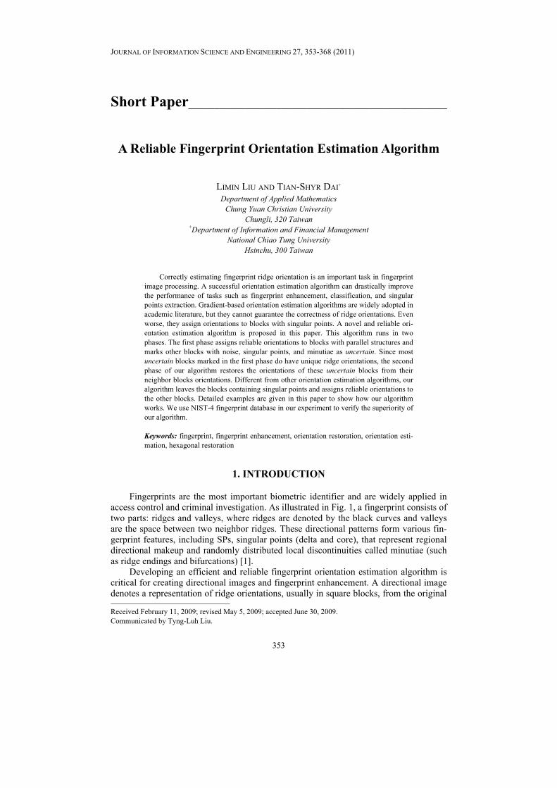
Fingerprints are the most important biometric identifier and are widely applied in access control and criminal investigation. As illustrated in Fig. 1, a fingerprint consists of two parts: ridges and valleys, where ridges are denoted by the black curves and valleys are the space between two neighbor ridges. These directional patterns form various fin-gerprint features, including SPs, singular points (delta and core), that represent regional directional makeup and randomly distributed local discontinuities called minutiae (such as ridge endings and bifurcations) [1].
Developing an efficient and reliable fingerprint orientation estimation algorithm is critical for creating directional images and fingerprint enhancement. A directional image denotes a representation of ridge orientations, usually in square blocks, from the original
Received February 11, 2009; revised May 5, 2009; accepted June 30, 2009. Communicated by Tyng-Luh Liu.
LIMIN LIU AND TIAN-SHYR DAI
354
Fig. 1. Fingerprint features: core point (in circle), delta point (in triangle), minutiae-ridge ending
(in diamond), and minutiae-ridge bifurcation (in square).
fingerprint. It can be used in fingerprint classification [2] and SP detection [3]. Thus, a poor orientation estimation algorithm could generate incorrect directional images and the fingerprints might be misclassified or marked with false SPs. Fingerprint enhancement algorithms can remove noise due to various reasons [4]. Anisotropic filtering approach that requires ridge orientations is widely adopted in fingerprint enhancement algorithms [5-11]. However, if the orientations are estimated incorrectly, then the enhancement al-gorithm might corrupt the real ridge patterns and generate false fingerprint features.
The performance of a fingerprint orientation estimation algorithm is greatly influ-enced by the quality of the fingerprint image. To differentiate high quality regions from poor quality regions, Hong et al. [6] divided ridge patterns into recoverable and unrecov-erable regions and they performed enhancement only on recoverable regions. Yao et al. [11] calculated the mean and variance of a sub-block of images to determine the quality of a fingerprint. However, neither was able to distinctly differentiate good regions from bad ones [12]. Ratha and Bolle proposed a method for image quality estimation in the wavelet domain which is unsuitable for uncompressed images [13]. Lee et al. [12] scaled the quality based on whether minutiae can be detected or not. Park and Kwon [14] pro-posed a quality measurement approach based on chain codes of directional slots in 8 di-rections, but this approach requires human experts.
Most of ridge orientation estimation algorithms are based on gray-scale relationship between pixels. Mehtre et al. [15] computed gray consistency along 16 directions at each pixel, and the orientation of the best consistency is taken as the ridge orientation. Hung [16] divided pixels into ridge and non-ridge pixels and estimated ridge orientation by computing the consistency of pixel type. Nagaty [17] and Zhu et al. [18] evaluated the correctness of ridge orientation based on neural network and the correctness of these methods depends highly on the data used in the learning phase. The most popular method for ridge orientation estimation is the gradient-based method [5, 6, 8, 10, 19-21]. It cal-culates the gradient vector of each pixel. Ideally, the gradient vector of an edge pixel would be orthogonal to the ridge orientation. However, if the dominate gradient of edge pixels is not orthogonal to the ridge, a falsely estimated orientation will result.
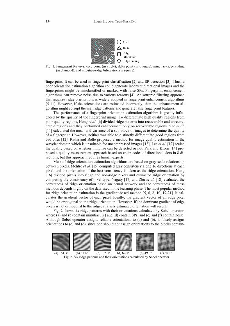
Fig. 2 shows six ridge patterns with their orientations calculated by Sobel operator, where (a) and (b) contain minutiae, (c) and (d) contain SPs, and (e) and (f) contain noise. Although Sobel operator assigns reliable orientations to (a) and (b), it falsely assigns orientations to (c) and (d), since one should not assign orientations to the blocks contain-
(a) 161.3º (b) 31.4º (c) 175.1º (d) 62.1º (e) 49.3º (f) 60.1º
Fig. 2. Six ridge patterns and their orientations calculated by Sobel operator.
A RELIABLE FINGERPRINT ORIENTATION ESTIMATION ALGORITHM
355
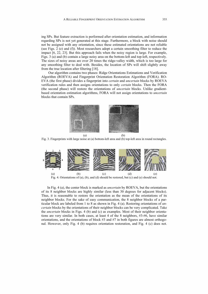
ing SPs. But feature extraction is performed after orientation estimation, and information regarding SPs is not yet generated at this stage. Furthermore, a block with noise should not be assigned with any orientation, since these estimated orientations are not reliable (see Figs. 2 (e) and (f)). Most researchers adopt a certain smoothing filter to reduce the impact [6, 22, 23]. But this approach fails when the noisy region is large. For example, Figs. 3 (a) and (b) contain a large noisy area on the bottom-left and top-left, respectively. The sizes of noisy areas are over 20 times the ridge-valley width, which is too large for any smoothing filter to deal with. Besides, the location of SPs will shift slightly away from the true location after filtering [18].
Our algorithm contains two phases: Ridge Orientations Estimations and Verification Algorithm (ROEVA) and Fingerprint Orientation Restoration Algorithm (FORA). RO-EVA (the first phase) divides a fingerprint into certain and uncertain blocks by ROEVA verification rules and then assigns orientations to only certain blocks. Then the FORA (the second phase) will restore the orientations of uncertain blocks. Unlike gradient- based orientation estimation algorithms, FORA will not assign orientations to uncertain blocks that contain SPs.
(a) (b)
Fig. 3. Fingerprints with large noise at (a) bottom-left area and (b) top-left area in round rectangles.
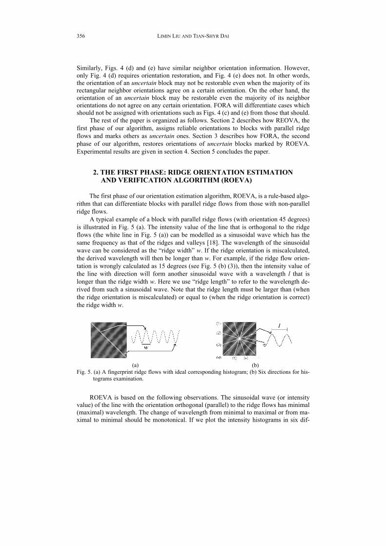
(a) (b) (c) (d)
(e) Fig. 4. Orientations of (a), (b), and (d) should be restored, but (c) and (e) should not.
In Fig. 4 (a), the center block is marked as uncertain by ROEVA, but the orientations of its 8 neighbor blocks are highly similar (less than 30 degrees for adjacent blocks). Thus, it is reasonable to restore the orientation as the mean of the orientations of its neighbor blocks. For the sake of easy communication, the 8 neighbor blocks of a par-ticular block are labeled from 1 to 8 as shown in Fig. 4 (a). Restoring orientations of un-certain blocks by the orientations of their neighbor blocks can be very complicated. Take the uncertain blocks in Figs. 4 (b) and (c) as examples. Most of their neighbor orienta-tions are very similar. In both cases, at least 4 of the 8 neighbors, #3-#6, have similar orientations, and the orientations of block #3 and #7 in both figures are almost orthogo-nal. However, only Fig. 4 (b) requires orientation restoration, and Fig. 4 (c) does not.
LIMIN LIU AND TIAN-SHYR DAI
356
Similarly, Figs. 4 (d) and (e) have similar neighbor orientation information. However, only Fig. 4 (d) requires orientation restoration, and Fig. 4 (e) does not. In other words, the orientation of an uncertain block may not be restorable even when the majority of its rectangular neighbor orientations agree on a certain orientation. On the other hand, the orientation of an uncertain block may be restorable even the majority of its neighbor orientations do not agree on any certain orientation. FORA will differentiate cases which should not be assigned with orientations such as Figs. 4 (c) and (e) from those that should.
The rest of the paper is organized as follows. Section 2 describes how REOVA, the first phase of our algorithm, assigns reliable orientations to blocks with parallel ridge flows and marks others as uncertain ones. Section 3 describes how FORA, the second phase of our algorithm, restores orientations of uncertain blocks marked by ROEVA. Experimental results are given in section 4. Section 5 concludes the paper.
2. THE FIRST PHASE: RIDGE ORIENTATION ESTIMATION AND VERIFICATION ALGORITHM (ROEVA)
The first phase of our orientation estimation algorithm, ROEVA, is a rule-based algo- rithm that can differentiate blocks with parallel ridge flows from those with non-parallel ridge flows.
A typical example of a block with parallel ridge flows (with orientation 45 degrees) is illustrated in Fig. 5 (a). The intensity value of the line that is orthogonal to the ridge flows (the white line in Fig. 5 (a)) can be modelled as a sinusoidal wave which has the same frequency as that of the ridges and valleys [18]. The wavelength of the sinusoidal wave can be considered as the “ridge width” w. If the ridge orientation is miscalculated, the derived wavelength will then be longer than w. For example, if the ridge flow orien-tation is wrongly calculated as 15 degrees (see Fig. 5 (b) (3)), then the intensity value of the line with direction will form another sinusoidal wave with a wavelength l that is longer than the ridge width w. Here we use “ridge length” to refer to the wavelength de-rived from such a sinusoidal wave. Note that the ridge length must be larger than (when the ridge orientation is miscalculated) or equal to (when the ridge orientation is correct) the ridge width w.
(a)
(b)
Fig. 5. (a) A fingerprint ridge flows with ideal corresponding histogram; (b) Six directions for his-tograms examination.
ROEVA is based on the following observations. The sinusoidal wave (or intensity value) of the line with the orientation orthogonal (parallel) to the ridge flows has minimal (maximal) wavelength. The change of wavelength from minimal to maximal or from ma- ximal to minimal should be monotonical. If we plot the intensity histograms in six dif-
A RELIABLE FINGERPRINT ORIENTATION ESTIMATION ALGORITHM
357
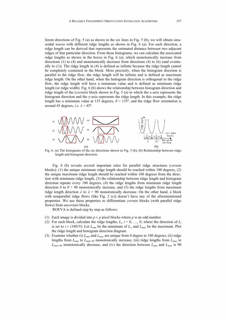
ferent directions of Fig. 5 (a) as shown in the six lines in Fig. 5 (b), we will obtain sinu-soidal waves with different ridge lengths as shown in Fig. 6 (a). For each direction, a ridge length can be derived that represents the estimated distance between two adjacent ridges of that particular direction. From these histograms, we can calculate the associated ridge lengths as shown in the boxes in Fig. 6 (a), which monotonically increase from directions (1) to (4) and monotonically decrease from directions (4) to (6) (and eventu-ally to (1)). The ridge length in (4) is defined as infinite because the ridge length cannot be completely contained in the block. More precisely, when the histogram direction is parallel to the ridge flow, the ridge length will be infinite and is defined as maximum ridge length. On the other hand, when the histogram direction is orthogonal to the ridge flow, the ridge length will have a minimum value and is defined as minimum ridge length (or ridge width). Fig. 6 (b) shows the relationship between histogram direction and ridge length of the (certain) block shown in Fig. 5 (a) in which the x-axis represents the histogram direction and the y-axis represents the ridge length. In this example, the ridge length has a minimum value at 135 degrees, θ = 135º, and the ridge flow orientation is around 45 degrees, i.e. λ = 45º.
(a)
(b)
Fig. 6. (a) The histograms of the six directions shown in Fig. 5 (b); (b) Relationship between ridge length and histogram direction.
Fig. 6 (b) reveals several important rules for parallel ridge structures (certain blocks): (1) the unique minimum ridge length should be reached within 180 degrees, (2) the unique maximum ridge length should be reached within 180 degrees from the direc-tion with minimum ridge length, (3) the relationship between ridge length and histogram direction repeats every 180 degrees, (4) the ridge lengths from minimum ridge length direction θ to θ + 90 monotonically increase, and (5) the ridge lengths from maximum ridge length direction λ to λ + 90 monotonically decrease. On the other hand, a block with nonparallel ridge flows (like Fig. 2 (c)) doesn’t have any of the aforementioned properties. We use these properties to differentiate certain blocks (with parallel ridge flows) from uncertain blocks.
ROEVA is defined step by step as follows:
(1) Each image is divided into p × p pixel blocks where p is an odd number. (2) For each block, calculate the ridge lengths, Li, i = 0, …, N, where the direction of Li
is set to i × (180/N). Let Lmin be the minimum of Li, and Lmax be the maximum. Plot the ridge length and histogram direction diagram.
(3) Examine whether (i) Lmin and Lmax are unique from 0 degree to 180 degrees, (ii) ridge lengths from Lmin to Lmin+90 monotonically increase, (iii) ridge lengths from Lmax to Lmax+90 monotonically decrease, and (iv) the direction between Lmin and Lmax is 90
LIMIN LIU AND TIAN-SHYR DAI
358
degrees. If all of the conditions above are satisfied, mark the block as a certain block and set the orientation to be max degrees, the direction of Lmax. Otherwise, mark this block as an uncertain block.
A block will be marked as uncertain due to minutiae, SPs, or noise. On the other
hand, if a block is marked as certain, then the orientation assigned to the block must be reliable. For example, six blocks in Fig. 2 are all marked as uncertain by ROEVA. Figs. 2 (a) and (b) are uncertain due to minutiae, and the orientations of these two blocks will be restored in FORA. Note that our algorithm will mark Figs. 2 (c) to (f) as uncertain instead of assigning approximate orientations and hoping they are correct. In our experi-ment, ROEVA on average can assign orientations to 49% of the blocks in the 4000 fin-gerprints in the NIST-4 database [24]. More details can be found in a previous study [25].
3. THE SECOND PHASE: FINGERPRINT ORIENTATION RESTORATION ALGORITHM (FORA)
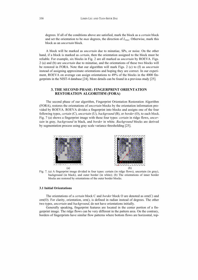
The second phase of our algorithm, Fingerprint Orientation Restoration Algorithm (FORA), restores the orientations of uncertain blocks by the orientation information pro-vided by ROEVA. ROEVA divides a fingerprint into blocks and assigns one of the four following types, certain (C), uncertain (U), background (B), or border (O), to each block. Fig. 7 (a) shows a fingerprint image with these four types: certain in ridge flows, uncer-tain in gray, background in black, and border in white. Background blocks are derived by segmentation process using gray scale variance thresholding [25].
(a)
(b)
Fig. 7. (a) A fingerprint image divided in four types: certain (in ridge flows), uncertain (in gray), background (in black), and outer border (in white); (b) The orientations of inner border blocks are restored by orientations of the outer border blocks.
3.1 Initial Orientations The orientations of a certain block C and border block O are denoted as orn(C) and
orn(O). For clarity, orientation, orn(), is defined in radian instead of degrees. The other two types, uncertain and background, do not have orientations initially.
Generally speaking, fingerprint features are located in the center portion of a fin-gerprint image. The ridge flows can be very different in the pattern area. On the contrary, borders of fingerprints have similar flow patterns where bottom flows are horizontal, top-
A RELIABLE FINGERPRINT ORIENTATION ESTIMATION ALGORITHM
359
left flows are around π/4, and top-right flows are around 3 · π/4. This property provides useful information in the restoration process. The border blocks are designed to depict this property and can be divided into two types: outer border and inner border.
The outer border blocks represent blocks outside the image. The ROEVA will slice an image, I, horizontally and vertically into Nx and Ny blocks. Then these blocks can be labeled as Ii,j where 1 ≤ j ≤ Nx and 1 ≤ i ≤ Ny. The top-left block is labeled as I1,1, and the bottom-right block is labeled as INy,Nx. The top outer border blocks are labeled as O0,0, O0,1, …, O0,Ny+1 from left to right, the bottom outer border blocks as ONy+1,0, ONy+1,1, …, ONy+1,Ny+1 from left to right, the left outer border blocks as O0,0, O1,0, …, ONy+1,0 from top to bottom, and the right outer border blocks as O0,Nx+1, O1,Nx+1, …, ONy+1,Nx+1 from top to bottom. Orientations of outer border blocks are defined based on six anchors: top-left anchor Tl(π/4), top-right anchor Tr(3 · π/4), middle-left anchor Ml(5 · π/12), middle-right anchor Mr(7 · π/12), bottom-left anchor Bl(π/6), and bottom-right anchor Br(5 · π/6). The orientations of outer border blocks are defined as follows:
orn(Oi,j) = ( ππ+⋅
+−+
− jN
TTTx
rll 1
) mod π, where i = 0 and 0 ≤ j ≤ Nx + 1, (1)
( ππ+⋅
+−+
− jN
BBBx
rll 1
) mod π, where i = Ny + 1 and 0 < j < Nx + 1,
,( 1) / 3
l ll
y
M TT iN
−+ ⋅
+ where 0 ≤ i ≤ (Ny + 1)/3 and j = 0,
( 1 ),2 ( 1) / 3
l ll y
y
M BB N iN
−+ ⋅ + −
⋅ + where (Ny + 1)/3 < i ≤ Ny + 1 and j = 0,
,( 1) / 3
r rr
y
T MT iN
−− ⋅
+ where 0 ≤ i ≤ (Ny + 1)/3 and j = Nx + 1,
( 1 ),2 ( 1) / 3
r rr y
y
B MB N iN−
− ⋅ + −⋅ +
where (Ny + 1)/3 < i ≤ Ny + 1 and j = Nx + 1.
The orientations of outer border blocks in Fig. 7 (a) are indicated by the black lines in white boxes. Note that the degrees of the six anchors designed to capture the ridge orientations of the border in fingerprints may be different on different fingerprint acqui-sition devices with different sizes of scanning area.
Sometimes, however, a fingerprint foreground does not cover the whole image. For instance, the top-left block and the bottom blocks in Fig. 7 (a) are marked as back-grounds. In such cases, since the outer border blocks are not adjacent to foreground fin-gerprint ridge patterns, the orientations of the outer border blocks cannot be used directly for the restoration process. To overcome this problem, inner border blocks are defined as those background blocks adjacent to fingerprint foreground. The orientation of an inner border block Ii,j is derived from outer border blocks by the following scheme. First, draw a line from the center of the image to the center of Ii,j and extend this line to the outer border blocks. Let Op,q be the outer border block whose outer frame is touched by the line, then the orientation of Ii,j is defined as the orientation of Op,q. For example, all of the background blocks in Fig. 7 (b) are considered inner border blocks, and their orienta-tions are represented in white lines. In Fig. 7 (b), the solid line starts from the center point of the fingerprint, phases through the center point of the inner border block O11,2,

LIMIN LIU AND TIAN-SHYR DAI
360
crosses the outer border block O12,2, and eventually touches the outer frame of the outer border block O12,1. The orientation of the inner border block I11,2 is then defined as the orientation of the outer border block O12,1. 3.2 Hexagonal Pattern
The proposed restoration algorithm is built on a hexagonal pattern with 6 neighbors
instead of a rectangular pattern with 8 neighbors because hexagonal pattern outperforms rectangular pattern in many aspects. For instance, the distance of neighbors can be dif-ferent in rectangular pattern. In Fig. 8 (a), the distance from the center of the top-left block to the center point is 2 times that from the center of the top-middle block to the center point. Furthermore, the four corner blocks are not physically connected to the cen-ter block. The proposed hexagonal pattern is derived from the 8-neighbor rectangular pattern in two directions: horizontal and vertical as shown in Figs. 8 (b) and (c), respec-tively. Each block in the hexagonal pattern will be assigned with a type (C, B, O, or U) and a ridge orientation (for type C or type O).
(a) (b) (c)
Fig. 8. (a) Rectangular pattern with 8-neighbor; (b) The horizontal hexagonal pattern of (a); (c) The vertical hexagonal pattern of (a).
For those blocks in hexagonal pattern that match the blocks in rectangular pattern, the orientations and types are inherited from the corresponding blocks in rectangular pat-tern. These blocks are located in the middle row of the horizontal and in the middle col-umn of the vertical hexagonal pattern. The orientations and types of the rest of the blocks in the hexagonal pattern are derived by the two blocks in rectangular pattern. Fig. 8 (a) shows a rectangular pattern with 9 blocks. Fig. 8 (b) shows its horizontal hexagonal pat-tern in which the orientation and type of the top-left block in the pattern is derived from blocks #1 and #2 in Fig. 8 (a). Fig. 8 (c) shows the vertical hexagonal pattern in which the orientation and type of the top-left block is derived from blocks #1 and #8 in Fig. 8 (a). Since a block can be one of the four types, there will be 16 combinations for deriving the orientation and type of a hexagonal block as shown in Table 1 with the following rules: Rule 1 If the difference between the orientations of these two blocks with the same type, C-C or O-O, is less than threshold h1, then return the average of these two orienta-tions with a type identical to those two blocks. Rule 2 If the two blocks have different types and one of them is certain, then the ori-entation of the certain block orn(C) with type certain is used for the hexagonal block.
A RELIABLE FINGERPRINT ORIENTATION ESTIMATION ALGORITHM
361
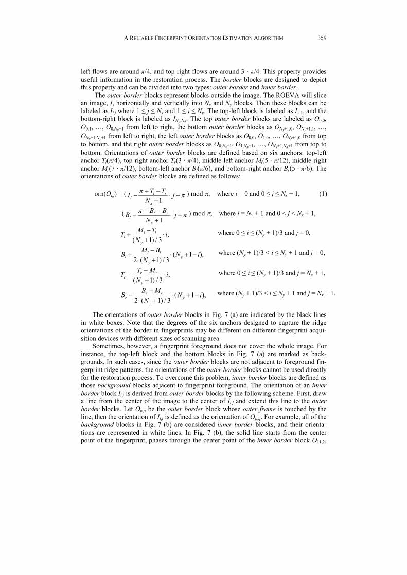
Rule 3 If the two blocks have different types and one of them is border, then the ori-entation of the border block orn(O) with type border is used for the hexagonal block.
Table 1. Definition of block orientation and type in hexagonal pattern. Orientation/ type C O U B
C Rule 1 Rule 2 Rule 2 Rule 2 O Rule 2 Rule 1 Rule 3 Rule 3 U Rule 2 Rule 3 unknown/U unknown/U B Rule 2 Rule 3 unknown/U unknown/B
These three rules apply for 12 of the 16 combinations in Table 1. The orientations of the rest four combinations are unknown with type uncertain (U) or background (B) as shown in Table 1. In our experiments, the threshold h1 in Rule 1 is π/4.
3.3 Processing Priority
Orientation restoration focuses on uncertain blocks which can be surrounded by 0 to 8 certain blocks. It is clear that a block surrounded by more certain blocks should be processed earlier than one surrounded by less, since more certain neighbors provide more concrete information about neighbor ridge flows. Similarly, a block surrounded by more border blocks should be processed earlier than one surrounded by less, since more border neighbors provide more referential information about neighbor ridge flows. For instance, Figs. 4 (a)-(c) have 8 certain neighbors and (d)-(e) have only 7 certain neigh- bors. Therefore, Figs. 4 (a)-(c) should be processed before (d)-(e). To implement this processing order, every uncertain block is assigned with a priority which equals the number of its certain neighbors plus 1/10 of the number of its border neighbors. Since certain neighbors provide more solid information than border neighbors, the multiplier 1/10 applied on the number of the border neighbors guarantees that blocks with more certain neighbors will be processed first. If the orientation of an uncertain block is re-stored, then the type of this block will become certain and, at the same time, the priority of its uncertain neighbors will be recalculated.
Since a block can have two directions on hexagonal pattern with 6 neighbor blocks, it is necessary to decide which direction to apply in the restoration process. Each block in hexagonal pattern is defined with weights 2, 1.5, 0, and 0 for types C, O, U, and B, re-spectively, based on the idea that blocks which provide more solid information should obtain more weights. A block which is both an inner border block and a background block will be considered as O. The weight of an uncertain block in hexagonal pattern is defined as the sum of weights of its hexagonal neighbours. An uncertain block may have weights from 0 to 12 in hexagonal pattern. If the vertical weight is different from the horizontal weight, then the direction with a higher weight is selected for the later restora-tion process. If the vertical weight is identical to the horizontal weight, then both direc-tions will be used for restoration process. Besides, if the restoration process concludes with unknown on one direction, the result of the other direction on the hexagonal pattern will be disregarded.

LIMIN LIU AND TIAN-SHYR DAI
362
3.4 Restoration Algorithm
The pseudo code of the Reliable Fingerprint Orientation Estimation Algorithm (RFOEA) is listed as follows which contains two phases: ROEVA and FORA. The algo-rithm takes a fingerprint image I as input and applies the ROEVA on I (line 4). In the mean time, all uncertain blocks are stored in a priority queue Q. If over half of the blocks in the pattern area are marked as uncertain, then FORA will not process I (line 5). The reason such images are rejected by FORA is that the pattern area contains important fea-tures: SPs. The FORA requires a certain number (over half of the pattern area) of clear blocks (certain blocks) to retain SPs in the restoration process. Consider an extreme situation in which an image contains no certain block in the pattern area, then the resto-ration process will proceed based solely on the orientations of border blocks. In such a case, global features, core and delta points, will be eliminated. To prevent that from hap-pening, FORA will not handle this kind of images.
1 2 3 4 5 6 7 8 9
10 11 12 13 14 15 16 17 18 19 20 21 22 23 24 25 26 27 28 29 30
Procedure RFOEA (Image I) create a priority queue Q; // First phase: perform ROEVA, and put all uncertain blocks into Q. ROEVA(I, Q); IF (over half blocks in pattern area are uncertain) EXIT(0); Int counter ← 0; WHILE (Q is not empty) // Second phase: FORA
Block b ← delete an element with highest priority from Q; Int wght_v ← nbr_weight(b, VERTICAL); Int wght_w ← nbr_weight(b, HORIZONTAL); Direction direction; IF (wght_v > wght_w)
direction ← VERTICAL; ELSE IF (wght_v < wght_w)
direction ← HORIZONTAL; ELSE IF (wght_v = wght_w)
direction ← BOTH; // determine whether the orientation can be restored. orientation ← hex_nbr_agreement(b, direction); IF (0 ≤ orientation AND orientation < 180)
print information of b with newly assigned orientation; recalculate element priority in Q; counter ← 0;
ELSE set the priority of b be 0; add b into Q; counter++; IF (counter equals to the element number of Q) EXIT(1);
ENDWHILE End of procedure
A RELIABLE FINGERPRINT ORIENTATION ESTIMATION ALGORITHM
363
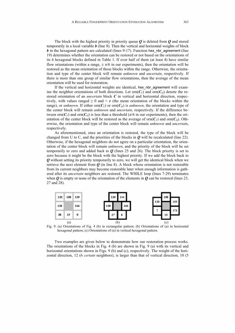
The block with the highest priority in priority queue Q is deleted from Q and stored temporarily in a local variable b (line 8). Then the vertical and horizontal weights of block b in the hexagonal pattern are calculated (lines 9-17). Function hex_nbr_agreement (line 19) determines whether the orientation can be restored or not based on the orientations of its 6 hexagonal blocks defined in Table 1. If over half of them (at least 4) have similar flow orientations (within a range, ± π/6 in our experiments), then the orientation will be restored as the mean orientation of those blocks within the range. Otherwise, the orienta-tion and type of the center block will remain unknown and uncertain, respectively. If there is more than one group of similar flow orientations, then the average of the mean orientation will be used for restoration.
If the vertical and horizontal weights are identical, hex_nbr_agreement will exam-ine the neighbor orientations of both directions. Let orn(CV) and orn(CH) denote the re-stored orientation of an uncertain block C in vertical and horizontal direction, respec-tively, with values ranged ≥ 0 and < π (the mean orientation of the blocks within the range), or unknown. If either orn(CV) or orn(CH) is unknown, the orientation and type of the center block will remain unknown and uncertain, respectively. If the difference be-tween orn(CV) and orn(CH) is less than a threshold (π/6 in our experiments), then the ori-entation of the center block will be restored as the average of orn(CV) and orn(CH). Oth-erwise, the orientation and type of the center block will remain unknown and uncertain, respectively.
As aforementioned, once an orientation is restored, the type of the block will be changed from U to C, and the priorities of the blocks in Q will be recalculated (line 22). Otherwise, if the hexagonal neighbors do not agree on a particular orientation, the orien-tation of the center block will remain unknown, and the priority of the block will be set temporarily to zero and added back to Q (lines 25 and 26). The block priority is set to zero because it might be the block with the highest priority. If we add the block back to Q without setting its priority temporarily to zero, we will get the identical block when we retrieve the next element from Q (in line 8). A block whose orientation is not restorable from its current neighbors may become restorable later when enough information is gath-ered after its uncertain neighbors are restored. The WHILE loop (lines 7-29) terminates when Q is empty or none of the orientation of the elements in Q can be restored (lines 23, 27 and 28).
(a)
(b)
(c)
Fig. 9. (a) Orientations of Fig. 4 (b) in rectangular pattern; (b) Orientations of (a) in horizontal hexagonal pattern; (c) Orientations of (a) in vertical hexagonal pattern.
Two examples are given below to demonstrate how our restoration process works. The orientations of the blocks in Fig. 4 (b) are shown in Fig. 9 (a) with its vertical and horizontal orientations shown in Figs. 9 (b) and (c), respectively. The weight of the hori-zontal direction, 12 (6 certain neighbors), is larger than that of vertical direction, 10 (5
LIMIN LIU AND TIAN-SHYR DAI
364
certain neighbors), since the orientation of the bottom-left block in Fig. 9 (c) cannot be determined from blocks #7 and #8 in Fig. 9 (a) by Rule 1. The orientation of the hori-zontal direction is 141º (average of 120º, 135º, 144º and 166º) because the differences between the orientations of the top four blocks are within a range of 60 degrees. This orientation, 141º, is then designated for the center block with type certain.
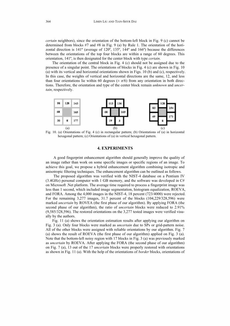
The orientation of the central block in Fig. 4 (c) should not be assigned due to the presence of a singular point. The orientations of blocks in Fig. 4 (c) are shown in Fig. 10 (a) with its vertical and horizontal orientations shown in Figs. 10 (b) and (c), respectively. In this case, the weights of vertical and horizontal directions are the same, 12, and less than four orientations lie within 60 degrees (± π/6) from any orientation in both direc-tions. Therefore, the orientation and type of the center block remain unknown and uncer-tain, respectively.
(a)
(b)
(c)
Fig. 10. (a) Orientations of Fig. 4 (c) in rectangular pattern; (b) Orientations of (a) in horizontal hexagonal pattern; (c) Orientations of (a) in vertical hexagonal pattern.
4. EXPERIMENTS
A good fingerprint enhancement algorithm should generally improve the quality of an image rather than work on some specific images or specific regions of an image. To achieve this goal, we propose a hybrid enhancement algorithm combining isotropic and anisotropic filtering techniques. The enhancement algorithm can be outlined as follows.
The proposed algorithm was verified with the NIST-4 database on a Pentium IV (3.4GHz) personal computer with 1 GB memory, and the software was developed in C# on Microsoft .Net platform. The average time required to process a fingerprint image was less than 1 second, which included image segmentation, histogram equalization, ROEVA, and FORA. Among the 4,000 images in the NIST-4, 18 percent (723/4000) were rejected. For the remaining 3,277 images, 31.7 percent of the blocks (104,229/328,596) were marked uncertain by ROVEA (the first phase of our algorithm). By applying FORA (the second phase of our algorithm), the ratio of uncertain blocks were reduced to 2.91% (9,585/328,596). The restored orientations on the 3,277 tested images were verified visu-ally by the authors.
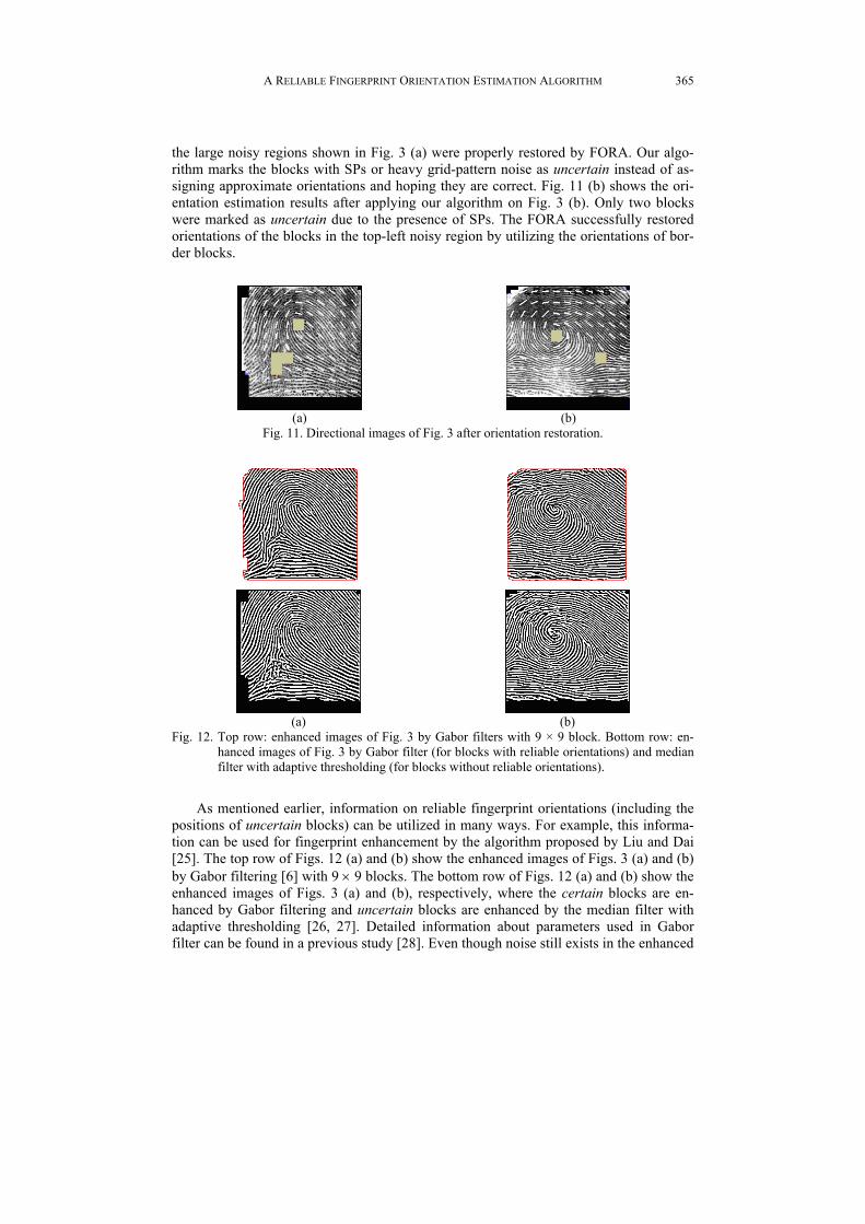
Fig. 11 (a) shows the orientation estimation results after applying our algorithm on Fig. 3 (a). Only four blocks were marked as uncertain due to SPs or grid-pattern noise. All of the other blocks were assigned with reliable orientations by our algorithm. Fig. 7 (a) shows the result of ROEVA (the first phase of our algorithm) applied on Fig. 3 (a). Note that the bottom-left noisy region with 17 blocks in Fig. 3 (a) was previously marked as uncertain by ROEVA. After applying the FORA (the second phase of our algorithm) on Fig. 7 (a), 13 out of the 17 uncertain blocks were properly restored with orientations as shown in Fig. 11 (a). With the help of the orientations of border blocks, orientations of
A RELIABLE FINGERPRINT ORIENTATION ESTIMATION ALGORITHM
365
the large noisy regions shown in Fig. 3 (a) were properly restored by FORA. Our algo-rithm marks the blocks with SPs or heavy grid-pattern noise as uncertain instead of as-signing approximate orientations and hoping they are correct. Fig. 11 (b) shows the ori-entation estimation results after applying our algorithm on Fig. 3 (b). Only two blocks were marked as uncertain due to the presence of SPs. The FORA successfully restored orientations of the blocks in the top-left noisy region by utilizing the orientations of bor-der blocks.
(a)
(b)
Fig. 11. Directional images of Fig. 3 after orientation restoration.
(a)
(b)
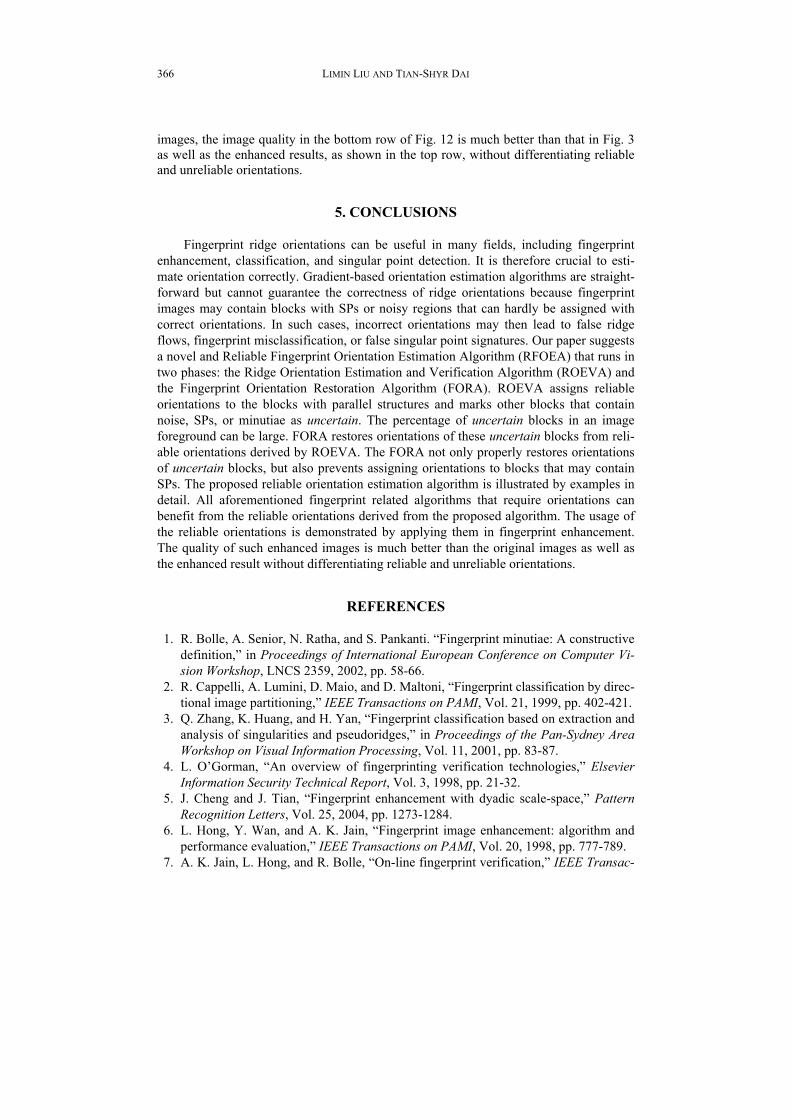
Fig. 12. Top row: enhanced images of Fig. 3 by Gabor filters with 9 × 9 block. Bottom row: en-hanced images of Fig. 3 by Gabor filter (for blocks with reliable orientations) and median filter with adaptive thresholding (for blocks without reliable orientations).
As mentioned earlier, information on reliable fingerprint orientations (including the positions of uncertain blocks) can be utilized in many ways. For example, this informa-tion can be used for fingerprint enhancement by the algorithm proposed by Liu and Dai [25]. The top row of Figs. 12 (a) and (b) show the enhanced images of Figs. 3 (a) and (b) by Gabor filtering [6] with 9 × 9 blocks. The bottom row of Figs. 12 (a) and (b) show the enhanced images of Figs. 3 (a) and (b), respectively, where the certain blocks are en-hanced by Gabor filtering and uncertain blocks are enhanced by the median filter with adaptive thresholding [26, 27]. Detailed information about parameters used in Gabor filter can be found in a previous study [28]. Even though noise still exists in the enhanced
LIMIN LIU AND TIAN-SHYR DAI
366
images, the image quality in the bottom row of Fig. 12 is much better than that in Fig. 3 as well as the enhanced results, as shown in the top row, without differentiating reliable and unreliable orientations.
5. CONCLUSIONS
Fingerprint ridge orientations can be useful in many fields, including fingerprint enhancement, classification, and singular point detection. It is therefore crucial to esti-mate orientation correctly. Gradient-based orientation estimation algorithms are straight-forward but cannot guarantee the correctness of ridge orientations because fingerprint images may contain blocks with SPs or noisy regions that can hardly be assigned with correct orientations. In such cases, incorrect orientations may then lead to false ridge flows, fingerprint misclassification, or false singular point signatures. Our paper suggests a novel and Reliable Fingerprint Orientation Estimation Algorithm (RFOEA) that runs in two phases: the Ridge Orientation Estimation and Verification Algorithm (ROEVA) and the Fingerprint Orientation Restoration Algorithm (FORA). ROEVA assigns reliable orientations to the blocks with parallel structures and marks other blocks that contain noise, SPs, or minutiae as uncertain. The percentage of uncertain blocks in an image foreground can be large. FORA restores orientations of these uncertain blocks from reli-able orientations derived by ROEVA. The FORA not only properly restores orientations of uncertain blocks, but also prevents assigning orientations to blocks that may contain SPs. The proposed reliable orientation estimation algorithm is illustrated by examples in detail. All aforementioned fingerprint related algorithms that require orientations can benefit from the reliable orientations derived from the proposed algorithm. The usage of the reliable orientations is demonstrated by applying them in fingerprint enhancement. The quality of such enhanced images is much better than the original images as well as the enhanced result without differentiating reliable and unreliable orientations.
REFERENCES
1. R. Bolle, A. Senior, N. Ratha, and S. Pankanti. “Fingerprint minutiae: A constructive definition,” in Proceedings of International European Conference on Computer Vi-sion Workshop, LNCS 2359, 2002, pp. 58-66.
2. R. Cappelli, A. Lumini, D. Maio, and D. Maltoni, “Fingerprint classification by direc- tional image partitioning,” IEEE Transactions on PAMI, Vol. 21, 1999, pp. 402-421.
3. Q. Zhang, K. Huang, and H. Yan, “Fingerprint classification based on extraction and analysis of singularities and pseudoridges,” in Proceedings of the Pan-Sydney Area Workshop on Visual Information Processing, Vol. 11, 2001, pp. 83-87.
4. L. O’Gorman, “An overview of fingerprinting verification technologies,” Elsevier Information Security Technical Report, Vol. 3, 1998, pp. 21-32.
5. J. Cheng and J. Tian, “Fingerprint enhancement with dyadic scale-space,” Pattern Recognition Letters, Vol. 25, 2004, pp. 1273-1284.
6. L. Hong, Y. Wan, and A. K. Jain, “Fingerprint image enhancement: algorithm and performance evaluation,” IEEE Transactions on PAMI, Vol. 20, 1998, pp. 777-789.
7. A. K. Jain, L. Hong, and R. Bolle, “On-line fingerprint verification,” IEEE Transac-

A RELIABLE FINGERPRINT ORIENTATION ESTIMATION ALGORITHM
367
tions on PAMI, Vol. 19, 1997, pp. 302-314. 8. D. Maio and D. Maltoni, “Direct gray-scale minutiae detection in fingerprints,”
IEEE Transactions on PAMI, Vol. 19, 1997, pp. 27-40. 9. L. O’Gorman and J. V. Nickerson, “An approach to fingerprint filter design,” Pat-
tern Recognition, Vol. 22, 1989, pp. 29-38. 10. J. Yang, L. Liu, T. Jiang, and Y. Fan, “A modified Gabor filter design method for
fingerprint image enhancement,” Pattern Recognition Letter, Vol. 24, 2003, pp. 1805-1817.
11. M. Yao, S. Pankanti, N. Haas, N. Ratha, and R. Bolle, “Quantifying quality: A case study in fingerprints,” in Proceedings of IEEE Conference on Automatic Identifica-tion Advanced Technologies, 2002, pp. 126-131.
12. S. Lee, C. Lee, and J. Kim, “Model-based quality estimation of fingerprint images,” in Proceedings of the International Conference on Biometrics, LNCS 3832, 2006, pp. 229-235.
13. N. Ratha and R. Bolle, “Fingerprint image quality estimation,” IBM Computer Science Research Report RC 21622, 1999.
14. J. Park and Y. Kwon, “Image quality measure using sliced block distance as a graphical element,” in Proceedings of the 5th International Workshop of Graphics Recognition: Recent Advances and Perspectives, LNCS 3088, 2003, pp. 211-222.
15. B. M. Mehtre, N. N. Murthy, S. Kapoor, and B. Chatterjee, “Segmentation of finger-print images using the directional image,” Pattern Recognition, Vol. 20, 1987, pp. 429-435.
16. D. Hung, “Enhancement and feature purification of fingerprint images,” Pattern Re- cognition, Vol. 26, 1993, pp. 1661-1671.
17. K. Nagaty, “On learning to estimate the block directional image of fingerprint using a hierarchical neural networks,” Neural Networks, Vol. 16, 2003, pp. 135-146.
18. E. Zhu, J. Yin, C. Hu, and G. Zhang, “A systematic method for fingerprint ridge ori-entation estimation and image segmentation,” Pattern Recognition, Vol. 39, 2006, pp. 1452-1472.
19. A. M. Bazen and S. H. Gerez, “Systematic methods for the computation of the direc-tional fields and singular points of fingerprints,” IEEE Transactions on PAMI, Vol. 24, 2002, pp. 905-919.
20. M. Kawagoe and A. Tojo, “Hung. Fingerprint pattern classification,” Pattern Rec-ognition, Vol. 17, 1984, pp. 295-303.
21. Y. Wang, J. Hu, and H. Schroder, “A gradient based weighted averaging method for estimation of fingerprint orientation fields,” in Proceedings of International Confer-ence on Digital Image Computing: Techniques and Applications, 2005, pp. 195-202.
22. B. M. Mehtre and B. Chatterjee, “Segmentation of fingerprint images − A composite method,” Pattern Recognition, Vol. 22, 1989, pp. 381-385.
23. B. M. Mehtre, “Fingerprint image analysis for automatic identification,” Machine Vision and Applications, Vol. 6, 1993, pp. 124-139.
24. C. I. Watson and C. L. Wilson, NIST Special Database 4, Fingerprint Database, Na-tional Institute of Standards and Technology, 1992.
25. L. Liu and T. Dai, “Ridge orientation estimation and verification algorithm for fin-gerprint enhancement,” Journal of Universal Computer Science, Vol. 12, 2006, pp. 1426-1438.

LIMIN LIU AND TIAN-SHYR DAI
368
26. H. Ailisto, M. Lindholm, and P. Tikkanen, “A review of fingerprint image enhance-ment methods,” International Journal of Image Graphics, Vol. 3, 2003, pp. 401-424.
27. C. Huang, L. Liu, and D. C. Hung, “Fingerprint analysis and singular point detec-tion,” Pattern Recognition Letters, Vol. 28, 2007, pp. 1937-1945.
28. L. Liu, C. Huang, and D. C. Hung, “A directional approach to fingerprint classifica-tion,” International Journal of Pattern Recognition and Artificial Intelligence, Vol. 22, 2008, pp. 347-365.
Limin Liu (劉立民) received his Ph.D. in Computer and Information Science from New Jersey Institute of Technology in 1999. He is currently an Associate Professor in the Department of Applied Mathematics at Chung Yuan Christian University, Taiwan. His current research interests include fingerprint technologies, image processing, OO model-ing, and computer-assisted learning.
Tan-Shyr Dai (戴天時) is currently an Associate Professor at the Department of
Information and Financial Management of the National Chiao Tung University, Taiwan. He obtained his Ph.D. in the Department of Computer Science and Information Engi-neering at National Taiwan University, Taiwan. His research interests are in financial engineering and algorithms.