a remote monitoring and control system for cultural
TRANSCRIPT

Linköping Studies in Science and Technology Dissertations, No. 1557
A Remote Monitoring and Control System for Cultural Heritage Buildings
Utilizing Wireless Sensor Networks
Jingcheng Zhang
Department of Science and Technology
Linköping University, SE-601 74 Norrköping, Sweden
Norrköping 2013

A Remote Monitoring and Control System for Cultural Heritage Buildings Utilizing Wireless Sensor Networks A dissertation submitted to ITN, Department of Science and Technology, Linköping
University, for the degree of Doctor of Technology.
ISBN: 978-91-7519-448-6
ISSN: 0345-7524
Copyright, 2013, Jingcheng Zhang, unless otherwise noted.
Linköping University
Department of Science and Technology
SE-601 74 Norrköping
Sweden
Printed by LiU-Tryck, Linköping 2013.

Abstract
i
ABSTRACT
This dissertation presents the study of a wireless remote monitoring and control system
utilized for cultural heritage preservation purpose. The system uses wireless sensor
networks to remotely monitor and control the indoor climate, i.e., temperature and
relative humidity of the cultural buildings.
The system mainly consists of three parts, i.e., the wireless sensor network part, the
gateway part and the web service part. Wireless sensor networks are deployed in
different cultural buildings. The ZigBee protocol is utilized for the wireless sensor
network communication. Sensor nodes report the indoor climate periodically. By
connecting with radiators and/or dehumidifiers, the wireless control nodes can control
the indoor climate according to the remote configuration. A gateway maintains the
communication between a wireless sensor network and the web service. In monitoring
function, the gateway forwards sensor messages from the wireless sensor network to
the web service. In control function, the gateway synchronizes the climate settings
from the web service to the wireless sensor network. The gateway also sends control
commands to the wireless control nodes in the wireless sensor network. The web
service provides a web-based user interface for the system.
Different from ordinary cable-connected sensor networks, a wireless sensor network
that works for cultural heritage preservation should be a system with a large number of
sensor nodes covering a large area in a building, high reliability in message
transmission, low power consumption and low cost. In this study, the performance of
the ZigBee wireless network is improved to meet such requirements base on the
investigation of the ZigBee protocol limitation. Firstly, a method for enhancing the
wireless sensor network communication reliability is developed. The reactive routing
protocol defined by the ZigBee standard is improved so that the wireless nodes
automatically detect and repair network communication problems. This method
minimizes the message lost within the wireless sensor network by always reserving a
route from the source node to the destination node. Secondly, a generic low power
working method is developed for sensor devices. This method defines the general
sensor module behavior which includes sensor data collecting, sensor message
forwarding and wireless network rejoining upon communication failure. It allows

Abstract
ii
sensor devices to maintain high message reliability with low power consumption.
Especially, these methods are developed as a complementary infrastructure of the
ZigBee wireless sensor network in order to increase the transmission reliability with
low power consumption. Finally, methods and algorithms are developed to make it
possible to power the ZigBee message relays (i.e., routers) with small batteries. In this
system, the whole ZigBee network is synchronized. Wireless communications within
the ZigBee network are scheduled so that every wireless transmission is collision-free.
During the period when no communication is scheduled, the router can go into low
power mode. This design improvement removes the original requirement of using
mains power for ZigBee message relays. A truly battery-driven and low power
consumption wireless sensor network is developed for monitoring cultural heritage
buildings without (or with limited) mains power.
The remote control function is developed to mainly prevent biological degradation by
controlling indoor climate, i.e., temperature and relative humidity. After studying the
requirements for heritage preservation, a high flexibility, high reliability and low cost
wireless indoor climate control system is developed. Different control algorithms are
implemented to achieve different control results.
Till today, the remote monitoring and control system presented in this dissertation has
been installed in 31 cultural heritage buildings both in Sweden and Norway.

Populärventenskaplig Sammanfattning
iii
POPULÄRVETENSKAPLIG SAMMANFATTNING
Denna avhandling presenterar en studie och ett utvecklat system för trådlös
fjärrövervakning och fjärrstyrning, med syftet att bevara kulturella och historiska
byggnader. Systemet använder trådlöst sensornätverk för att övervaka och styra
inomhusklimat, t.ex., temperatur och relativ luftfuktighet i byggnaderna.
Systemet består huvudsakligen av tre delar, nämligen trådlöst sensornätverk, gateway
och webbtjänst. Trådlösa sensornätverk installeras i olika kulturella och historiska
byggnader. ZigBee-protokollet utnyttjas för det trådlösa sensornätverkets
kommunikation. Sensornoderna rapporterar periodiskt inomhusklimat. När element
och/eller avfuktare är anslutna till trådlösa sensornätverket, kan de trådlösa styrnoderna
styra inomhusklimat enligt konfiguration via webbtjänst. En gateway underhåller
kommunikationen mellan trådlöst sensornätverk och webbtjänst. För övervakning
skickar gateway vidare mätdata från ett trådlöst sensornätverk till webbtjänsten. För
styrning, synkroniserar gateway klimatsinställningar från webbtjänsten till det trådlösa
sensornätverket. Gateway-enheten skickar också styrkommandon till trådlösa styrnoder
i trådlösa sensornätverket. Webbtjänsten är ett webb-baserat användargränssnitt för
systemet.
I denna studie förbättras prestation av det standariserade ZigBee-protokollet baserad på
undersökning av befintliga begränsningar. För det första, en metod utvecklas för att
förhöja kommunikationspålitlighet av trådlösa sensornätverk, så att de trådlösa noderna
automatiskt detekterar och reparerar kommunikationsproblem. För det andra, utvecklas
en allmän lågeffektförbrukningsmetod för trådlösa sensornoderna, vilket tillåter
sensorenheter att åstadkomma hög datakommunikationspålitlighet samtidigt låg
effektförbrukning. Slutligen, har metoder och algoritmer utvecklats för att effektivt
driva ZigBee-router på batteri istället för fast spänning. I detta system synkroniseras
hela ZigBee-nätverket. Trådlösdatakommunikation i ZigBee-nätverket är schemalagd
så att varje trådlös dataöverföring är utan kollision. Utanför schemalagda perioderna
kan då ZigBee-routrar gå till lågeffektläge. Detta leder verkligen till ett batteri-drivet
trådlöst sensornätverk med låg effektförbrukning, vilket passar bra för användning i de
gamla kulturella och historiska byggnaderna.

Populärvetenskaplig sammanfattning ___________________________________________________________________________________________________
iv
Tills idag, har detta utvecklade system för fjärrövervakning och fjärrstyrning
installerats i 31 byggnader i Sverige samt Norge.

Acknowledgement
v
ACKNOWLEDGEMENT
First of all I would like to express my gratitude to my supervisor Professor Qin-Zhong
Ye and Professor Shaofang Gong, for their guidance, supports and for giving me the
opportunity to perform this challenging and interesting research work in the research
group. Furthermore, I want to thank those people at the Department of Science and
Technology who in various ways have supported me in my work. Especially, I want to
express my gratitude to the following persons:
People in the Communication Electronics Research Group: Dr. Allan Huynh, Dr.
Adriana Serban, Gustav Knutsson, Dr. Magnus Karlsson, and Patrik Huss.
Vinnova, Swedish Energy Agency, Swedish Church and Norrköping municipality are
acknowledged for financial support of this work. Dr. Tor Broström, Jan Holmberg and
Magnus Wessberg at Uppsala University are acknowledged for valuable inputs to the
project.
Also thanks to all my dear friends for their friendship, all the laugh and support. They
have really made these years a very pleasant journey.
Last but not least, I would like to thank my wife Juan Chen, my parents Shenghua
Huang and Weijiang Zhang, my parents in law Suying Gu and Hongshuang Chen, for
their constant support and love.
Jingcheng Zhang,
Norrköping, December 2013.

Publications
vi
LIST OF PUBLICATIONS
Papers included in this dissertation:
Paper 1 Jingcheng Zhang, Allan Huynh, Qin-Zhong Ye and Shaofang Gong, “Remote Sensing System for Cultural Buildings Utilizing ZigBee Technology”, Proceedings of the 8th International Conference on Computing, Communications and Control Technologies (CCCT 2010), Orlando, USA, pp. 71-77, April 2010.
Paper 2 Jingcheng Zhang, Allan Huynh, Qin-Zhong Ye and Shaofang Gong, “Design of the Remote Climate Control System for Cultural Buildings Utilizing ZigBee Technology”, Sensors & Transducers Journal (ISSN 1726-5479), Vol. 118, Issue 7, pp. 13-27, July 2010.
Paper 3 Jingcheng Zhang, Allan Huynh, Qin-Zhong Ye and Shaofang Gong, “Reliability and Latency Enhancements in a ZigBee Remote Sensing System”, Proceedings of 4th International Conference on Sensor Technologies and Applications (SENSORCOMM 2010), Venice/Mestre, Italy, pp. 196-202, July 2010.
Paper 4 Jingcheng Zhang, Allan Huynh, Qin-Zhong Ye and Shaofang Gong, “A Fully Wireless Monitoring and Control System for Protecting Cultural Heritage”, Proceedings of 20th IEEE International Conference on Collaboration Technologies and Infrastructures, Paris, France, pp. 51-57, June 2011.
Paper 5 Jingcheng Zhang, Allan Huynh, Qin-Zhong Ye and Shaofang Gong, “A Communication Reliability Enhancement Framework for the ZigBee Wireless Sensor Network”, Sensors & Transducers Journal (ISSN 1726-5479), Vol.135, Issue 12, pp. 42-56. 2012.
Paper 6 Jingcheng Zhang, Allan Huynh, Qin-Zhong Ye and Shaofang Gong, “A Web-based Remote Indoor Climate Control System Based on Wireless Sensor Network”, International Journal of Sensors and Sensor Networks, Vol. 1, No. 3, June 2013.
Paper 7 Jingcheng Zhang, Qin-Zhong Ye, Allan Huynh and Shaofang Gong, “Design and Implementation of a Truly Battery-Driven ZigBee Wireless Sensor Network”, Manuscript, September, 2013.

Publications
vii
The author has also been involved in the following papers not included in this thesis.
Paper 8 Allan Huynh, Jingcheng Zhang, Qin-Zhong Ye and Shaofang Gong, “ZigBee Radio with External Low-Noise Amplifier”, Sensors & Transducers Journal (ISSN 1726-5479), Vol. 114, Issue 3, pp. 184-191, March 2010.
Paper 9 Allan Huynh, Jingcheng Zhang, Qin-Zhong Ye and Shaofang Gong, “ZigBee Radio with External Power Amplifier and Low-Noise Amplifier”, Sensors & Transducers Journal (ISSN 1726-5479), Vol. 118, Issue 7, pp. 110-121, July 2010.
Paper 10 Allan Huynh, Jingcheng Zhang, Qin-Zhong Ye and Shaofang Gong, “Wireless Remote System Monitoring for Cultural Heritage”, Sensors & Transducers Journal (ISSN 1726-5479), Vol. 118, Issue 7, pp. 1-12, July 2010.


List of Abbreviations
ix
LIST OF ABBREVIATIONS
BER Bit Error Rate
CRC Cyclic Redundancy Check
CSMA-CA Carrier Sense Multiple Access – Collision Avoidance
dB Decibel
DHCP Dynamic Host Configuration Protocol
DUT Device Under Test
FFD Full Function Device
FTDI Future Technology Devices International
HART Highway Addressable Remote Transducer
HVAC Heating, Ventilation, and Air-Conditioning
IC Integrated Circuit
IEEE Institute of Electrical and Electronics Engineers
ITN Department of Science and Technology
IP Internet Protocol
kbps Kilo bits per second
LAN Local Area Network
LED Light Emitting Diode
LiU Linköping University
LNA Low-Noise Amplifier
LOS Line of Sight
LQI Link Quality Indication
MCU Microcontroller Unit
M2M Machine to machine
NWK Network
PA Power Amplifier
PCB Printed Circuit Board
PER Packet Error Rate
RF Radio Frequency
RFD Reduced Function Device
RSSI Received Signal Strength Indicator
Rx Receiver

List of Abbreviations
x
SC Synchronization Controller
SoC System-on-Chip
TI Texas Instruments
Tx Transmitter
UART Universal Asynchronous Receiver/Transmitter
UI User interface
USB Universal Serial Bus
UWB Ultra Wide Band
WLAN Wireless Local Area Network
WSN Wireless Sensor Network
ZC ZigBee Coordinator
ZED ZigBee End-Device
ZR ZigBee Router

Contents
xi
Contents
Abstract ...................................................................................................................... i
Populärvetenskaplig sammanfattning ..................................................................... iii
Acknowledgement ......................................................................................................v
List of Publications ................................................................................................... vi
List of Abbreviations ................................................................................................ ix
1 Introduction........................................................................................................1
1.1 Background and motivation ..........................................................................1
1.2 Objectives ....................................................................................................2
1.3 Thesis outline ...............................................................................................4
2 Applications and Protocols of Wireless Sensor Networks ................................5
2.1 Introduction of three IEEE 802.15.4 based protocols ....................................6
2.2 Protocol comparison .....................................................................................7
2.2.1 Protocol comparison according ISO 7-layer architecture ..........................7
2.2.2 Protocol comparison according to the cultural heritage preservation
requirements ............................................................................................9
2.3 ZigBee standard ......................................................................................... 10
2.4 ZigBee WSN adaptation for heritage preservation purpose ......................... 12
3 General System Description............................................................................. 13
3.1 Remote monitoring system architecture ...................................................... 14
3.2 Remote control function description ........................................................... 14
3.3 Hardware description ................................................................................. 15
4 Remote Monitoring and Control System ........................................................ 19
4.1 Wireless monitoring and control networks .................................................. 19
4.1.1 Reliability enhancement ......................................................................... 19
4.1.2 Router firmware design .......................................................................... 24
4.1.3 End device firmware design ................................................................... 25
4.1.4 WSN control function Implementation ................................................... 31
4.1.5 Truly battery-driven ZigBee network ..................................................... 33
4.2 Local manager ............................................................................................ 38
4.2.1 Local manager software architecture ...................................................... 39

Contents
xii
4.2.2 Monitoring and warning function .......................................................... 40
4.2.3 Control function .................................................................................... 43
4.2.4 Control algorithm implementation ......................................................... 47
4.3 Web service ............................................................................................... 51
5 Result ............................................................................................................... 55
6 Summary of the Included Papers ................................................................... 57
Bibliography ............................................................................................................ 63
Paper I...................................................................................................................... 71
Remote Sensing System for Cultural Buildings Utilizing ZigBee Technology ...... 73
I. Introduction ..................................................................................................... 73
II. System Overview ............................................................................................. 74
III. System Design .................................................................................................. 75
a. ZigBee network data collection package .................................................... 75
b. Local server data manipulation package..................................................... 80
c. Main server web service package ............................................................... 81
IV. Test Setup ........................................................................................................ 82
a. Power consumption test set-up................................................................... 82
b. Network stability test ................................................................................. 83
V. Test Result ...................................................................................................... 84
a. Current consumption test result ................................................................. 84
b. Network stability test ................................................................................. 87
VI. Discussion ........................................................................................................ 88
VII. Conclusion ....................................................................................................... 89
VIII.Acknowledgement ........................................................................................... 89
References ................................................................................................................ 90
Paper II .................................................................................................................... 93
Design of the Remote Climate Control System for Cultural Buildings Utilizing ZigBee Technology .......................................................................................... 95
I. Introduction ..................................................................................................... 95
II. Remote Control System Overview .................................................................. 96
III. Software Design of Wireless Sensor Network ................................................ 98

Contents
xiii
a. Control node registration ............................................................................ 99
b. Sensor node service discovery .................................................................. 101
c. Sensor node working state machine .......................................................... 102
d. Control node operation ............................................................................. 105
IV. Software Design of the Local Server ............................................................. 105
a. Control and sensor node registration ......................................................... 106
b. Sensor reading information synchronization ............................................. 107
c. Local server command polling.................................................................. 108
V. Software Design of the Main Server .............................................................. 109
VI. Design Result Discussion ................................................................................ 112
a. System inter-dependency .......................................................................... 112
b. Service extension and reuse ...................................................................... 113
c. Automatic configuration ........................................................................... 113
d. Passive command polling v.s. direct command forwarding ....................... 114
VII. Conclusion ...................................................................................................... 114
Acknowledgements ................................................................................................. 114
References ............................................................................................................... 114
Paper III ................................................................................................................. 117
Reliability and Latency Enhancements in a ZigBee Remote Sensing System ...... 119
I. Introduction.................................................................................................... 119
II. System Enhancement Software Design in ZigBee Network ......................... 121
a. Control and configure the network topology ............................................. 122
b. Optimize the ZigBee network latency ....................................................... 124
c. Routers restore network information from flash memory after power reset
…………………………………………………………………………….125
III. System Enhancement Design in Local Server ............................................... 126
a. ZigBee network failure warning function ................................................. 126
b. Software data buffer for Internet fault tolerance ........................................ 127
IV. Latency Test Set-up........................................................................................ 129
a. AODV routing discovery minimum latency measurement ........................ 129
b. “Follow the topology” routing method latency measurement ................... 131
V. Network Test Result ....................................................................................... 132

Contents
xiv
a. Network latency test result summary ....................................................... 132
b. Temperature and humidity measurement results using our monitoring system
…………………………………………………………………………….133
VI. Discussion ...................................................................................................... 136
VII. Conclusion ..................................................................................................... 138
Acknowledgement.................................................................................................. 138
References .............................................................................................................. 138
Paper IV ................................................................................................................. 141
CultureBee – A Fully Wireless Monitoring and Control System for Protecting Cultural Heritage .......................................................................................... 143
I. Introduction ................................................................................................... 143
II. Component Design ........................................................................................ 145
a. Wireless sensor network software design ................................................. 145
b. Local server software design.................................................................... 149
c. Main server software design .................................................................... 151
III. Wireless Sensor Network Optimization........................................................ 152
a. Wireless data forwarding method optimization ........................................ 152
b. Connection status warning function ......................................................... 155
c. System buffer function implementation ................................................... 157
IV. Test Setup ...................................................................................................... 159
a. Power consumption test set-up................................................................. 159
b. AODV and “Direct parent forwarding” latency comparison ..................... 160
V. Test Result ..................................................................................................... 161
a. Power consumption test result ................................................................. 161
b. AODV and “Direct parent forwarding” performance comparison test result
…………………………………………………………………………….162
c. CultureBee system deployment and measurement result .......................... 163
VI. Discussions ..................................................................................................... 166
VII. Conclusions .................................................................................................... 167
Acknowledgement.................................................................................................. 167
References .............................................................................................................. 167
Paper V .................................................................................................................. 169

Contents
xv
A Communication Reliability Enhancement Framework for Wireless Sensor Network Using the ZigBee Protocol .............................................................. 171
I. Introduction.................................................................................................... 171
a. End device cannot send message to the coordinator due to the router failure
…………………………………………………………………………….172
b. New devices joining the sensor network by associating the router with
broken link ............................................................................................... 173
c. Battery lifetime deceases when the end device lost connection with the
sensor network ......................................................................................... 173
II. Message-flow Design to Increase the Network Communication Reliability 174
a. Add “handshake” messages between the router and the end device ........... 174
b. Router with communication problem denies “association request” of the new
device ....................................................................................................... 175
c. End device detests the network before rejoin via association .................... 176
d. Flash memory based circular buffer design for the end device .................. 178
III. Design A General Purpose State Machine to increase the message reliability………………………………………………………………………………….178
a. End device reliability enhancement state machine .................................... 179
b. Router reliability enhancement state machine ........................................... 181
IV. Power consumption measurement ................................................................. 183
a. Basic end device operation power consumption measurement .................. 183
b. End device operation power consumption after reliability enhancement ... 184
c. Battery lifetime calculation....................................................................... 187
V. Discussion ....................................................................................................... 188
a. Utilize the framework to check the communication status other than the
coordinator ............................................................................................... 188
b. Different architecture configuration of the enhancement framework with the
ZigBee stack ............................................................................................ 189
c. Possibility of lost sensor data under different interval configuration ......... 191
VI. Conclusion ...................................................................................................... 192
References ............................................................................................................... 193
Paper VI.................................................................................................................. 195
A Web-based Remote Indoor Climate Control System Based on Wireless Sensor Network .......................................................................................................... 197

Contents
xvi
I. Background Introduction ............................................................................. 197
II. Remote Control System Architecture Description ....................................... 198
III. Wireless Sensor Network .............................................................................. 200
a. Devices of wireless sensor network ......................................................... 200
b. Wireless sensor network message flow .................................................... 202
IV. Local Server Design ....................................................................................... 204
a. Control function component design ......................................................... 206
b. Warning function component design........................................................ 210
V. Web Service Design ....................................................................................... 212
VI. Test Result ..................................................................................................... 212
VII. Discussion ...................................................................................................... 214
VIII.Conclusion ..................................................................................................... 216
Acknowledgements ................................................................................................ 216
References .............................................................................................................. 216
Paper VII ............................................................................................................... 221
Design and Implementation of a Truly Battery-Driven Low Power ZigBee Wireless Sensor Network .............................................................................. 223
I. Background Introduction ............................................................................. 223
II. Related Work................................................................................................. 225
III. Wireless Sensor Network Device Hardware Construction .......................... 226
IV. ZigBee Router Synchronization Controller Software Design ...................... 227
V. Communication Between Battery-Driven Router and the Concentrator ... 229
a. Router registration process ...................................................................... 229
b. Uploading sensor message process .......................................................... 231
c. Rejoining network process ....................................................................... 233
d. Router operation state machine ................................................................ 234
VI. Communication Between Battery-Driven Router and End Devices ............ 235
a. End device registration process ................................................................ 236
b. Sending sensor message process .............................................................. 237
c. Rejoining the WSN process ..................................................................... 239
VII. Wireless Sensor Network Optimization........................................................ 242
a. Fetching sensor message from router ....................................................... 242

Contents
xvii
b. Sensor report time window allocation ....................................................... 244
VIII.Power Consumption Test Setup and Test Result .......................................... 246
a. Uploading sensor messages ...................................................................... 247
b. Receiving sensor messages ....................................................................... 251
c. Battery lifetime calculation....................................................................... 253
IX. Discussion ....................................................................................................... 254
a. Router handling multiple tasks ................................................................. 254
b. Time synchronization in the ZigBee WSN with battery-powered routers .. 255
c. Sensor message aggregation ..................................................................... 256
d. Battery-powered router WSN network scale ............................................. 257
X. Conclusion ...................................................................................................... 258
References ............................................................................................................... 259


Introduction
1
1 Introduction
Fast development of Information and Communications Technology (ICT) and
emerging Internet of Things (IoT) systems bring many advantages to the modern
society [1]. More and more sensor technologies are utilized in our daily life. By
considering together with the collected ambient information, our life can become more
efficient, more secure and more comfortable. The digital society based on massive data
collection and smart data handling is the trend for the future development. Meanwhile,
people are also looking for the possibilities to utilize wireless sensor technologies in
cultural heritage preservation area. This dissertation presents a system solution of
utilizing wireless sensor networks to remotely monitor and control the indoor climate
of cultural and historical buildings for heritage preservation purpose.
1.1 Background and motivation
Cultural heritage preservation research based on mathematic modeling and material
analysis requires long term and continues measurement results [2]. Each cultural
building has its unique indoor climate characteristic. In order to generalize the common
behavior, many buildings need to be measured at the same time. Among these
buildings, some of them might be geographically located far away from each other. A
web-based remote monitoring system can be used for data collecting purpose. By
deploying data logging systems in different cultural buildings, the measured data can
be forwarded to the remote web service via the Internet. Such data can be further
analyzed according to specific research requirements.

Objectives
2
Cultural heritage buildings, e.g., churches or museums, should also provide a good
indoor environment for human activities. During this time, the indoor climate of the
cultural building should be adjusted to a comfortable level. When the building is not
used, the indoor climate should be maintained for heritage preservation purpose.
Biological degradation problems, e.g., mold, should be avoided in the cultural heritage
buildings. A remote control function can be developed for both requirements. Users
could remotely control the indoor climate in cultural buildings by issuing activity
schedules from the web service. During the time when the building is not used, the
control system maintains the minimum climate requirement for heritage preservation
purpose.
1.2 Objectives
Wireless sensor networks can bring lots of benefit for cultural heritage preservation.
Firstly, compared with the wired system, a wireless system installation requires much
less building modifications. Wired communications are replaced by wireless
communications. By installing such systems, the cultural heritage buildings are
maximally kept unchanged. Secondly, compared with wired system, the wireless
system deployment is much more cost effective. The wired system roughly cost $10
per meter which including the material fee and installation cost [3]. In contrast, a
wireless device can be deployed anywhere within the wireless communication range.
Thirdly, wireless systems are much more flexible and easy to be extended. By utilizing
wireless communications, wireless sensor nodes can be placed at anyplace within the
wireless network range. Many measurement points can be easily added according to the
requirements. For example, a wireless sensor for measuring temperature and relative
humidity can be put into the wardrobe for mold problem detection. After the
measurement, the same sensor could be moved to another place for other microclimate
detection purpose.
However, implementing a wireless sensor network for remote monitoring of cultural
heritage buildings is very challenging. Different from a normal living environment,
cultural heritage buildings have some unique characteristics. Firstly, these types of
buildings are usually much bigger than ordinary houses. They were usually constructed
from stone and built in many floors. In order to measure the indoor climate in such
buildings, around 20 to 40 sampling points are required for each building. For each

Introduction
3
point, the measured result should be reported every 15 minutes. Secondly, most of the
cultural buildings are built before the invention of electricity. Power outlets in such
buildings are very limited. Thirdly, the media inside the cultural buildings can change
dynamically. For example, the relative humidity can change from 20 to 95% from
winter to summer. The indoor climate fluctuation brings a lot of uncertainty to the
wireless signal transmission [4]. Nevertheless, as a monitoring system, the package loss
rate [5] should be as low as possible. By summarizing the requirements, a wireless
sensor network that works for cultural heritage preservation should have the following
characteristics.
Large scale wireless sensor network: The size of the wireless sensor network
should be large enough to cover a big cultural building.
Low power consumption: Power outlets are very limited in cultural buildings.
The wireless sensor network should be mainly powered by battery with long
battery lifetime.
High message transmission reliability: The measured data should be
successfully sent from the wireless sensor network to the web service.
Different from the monitoring system, the remote control function focuses on
preserving cultural buildings which are “occasionally used”. Usually, a daily used
church is well equipped with heating and ventilation systems. Such systems can
provide good environment for both human activities and heritage preservation.
However, situations in the “occasionally used” churches are different [6]. Firstly, such
churches are only used several times per year. It is neither practical nor effective to
maintain a similar indoor climate as daily used churches. Secondly, the size of such
churches is usually small. Heating systems in such churches are very old and low
efficient. Thirdly, due to lack of maintenance, the relative humidity inside the church
can be higher than 80%. In order to preserve heritage in such churches, a low cost,
easy-to-install and maintenance-free indoor climate control solution is highly
appreciated. Especially, the remote control function should provide the following
features.
A web based control system which can remotely configure the indoor climate in
different cultural buildings.
Two kinds of control mode. One mode works for providing a good indoor
climate during human activities. Another mode works only for heritage

Objectives
4
preservation when the building is not used. Compared with the temperature
required for human activities, the temperature requirement for heritage
preservation is always lower [7]. A lot of energy can be saved by maintaining a
lower temperature, which is good for small churches with limited budget.
Different control algorithms. Different control algorithms should be developed
for different control purposes. During the human activities, the indoor
temperature should be maintained in a comfortable level. During the time when
the church is not used, the relative humidity should be controlled to prevent
mold problem.
High flexibility. The same control node could work for different control tasks
based on the user configuration. For example, a wireless control node can be
configured to control temperature by connecting a radiator. Afterwards, the
same control node could also be configured to control relative humidity by
connecting a dehumidifier.
High reliability. All control operations should be done under surveillance.
1.3 Thesis outline
This thesis is organized as the following. Chapter 2 describes the existing wireless
sensor network standard. The ZigBee standard is selected as the communication
protocol for the wireless sensor network. By comparing the ZigBee protocol with the
cultural heritage preservation requirements, limitations of the ZigBee protocol are
listed. Chapter 3 presents the system architecture of the remote monitoring and control
system. It also includes the description of hardware devices utilized in this study.
Chapter 4 elaborates the design and implementation for the remote monitoring and
control functions. The wireless sensor network, the gateway and the web service are
presented accordingly. Chapter 5 includes a summary of the study results.

Applications and Protocols of Wireless Sensor Networks
5
2 Applications and Protocols of Wireless Sensor Networks
A wireless sensor networks (WSN) usually consists of wireless devices installed with
radio transceivers. Distributed mechanism is utilized in the WSN so that an ad-hoc
WSN topology is created which can be changed dynamically. WSN was first motivated
by military monitoring applications during the 1980s. Till today, large scale WSN
applications are becoming a reality, for example, Smart Grid [8] [9] [10] [11], internet
of things [12] [13] [14] and Machine to machine (M2M) communication networks [15]
[16] [17]. The idea of utilizing wireless technology on cultural heritage preservation
purpose has been proposed for many years. Lots of researches have been done on
monitoring the structural health of a building by detecting building vibration [18]-[25].
Utilizing wireless sensor network for indoor climate monitoring and control is also an
active research area [26]-[29]. Different applications on utilizing wireless sensor
network are presented in different novel methods.
Besides different applications, the development of WSN infrastructure is always
aiming at low-power and low cost. As the network scale is growing bigger and bigger,
power efficient routing algorithms for large scale WSN are more and more crucial for
the network performance. To achieve this goal, a common approach is to divide a large
WSN into different smaller zones using topology control methods. J. N. Ai-Karaki et al.
proposed a data power-efficient routing paradigm using data aggregation [30]. Wireless
devices are virtually divided in different zones. Inside each zone, a wireless node is
optimally selected as the master. Sensor data are collected in two levels, both locally
(inside the zone) and globally (inter-zone). This method assumes that all wireless
devices are extremely stationary since the zone reestablishment introduce very high
overhead into the WSN. Q. Li et al. proposed a hierarchical power-aware routing

Introduction of three IEEE 802.15.4 based protocols
6
algorithm [31]. A global zone to zone path is calculated according to the power level of
each zone. The path is controlled by a global controller which could be the wireless
node with the highest power. Alternatively, a multi-zoned wireless sensor network
could have more than one data sink. F. Ye et al. proposed a so called Two-Tier Data
Dissemination (TTDD) [32] algorithm which delivers sensor messages to multiple
mobile data sinks. The routing paths between the source and the data sink are actively
discovered by the sensor using greedy geographical forwarding [33]. TTDD algorithm
provides an efficient message routing by assuming that a very accurate positioning
system is equipped in the WSN.
Moreover, many standards and protocols are defined for WSNs [34]. Generally, these
protocols can be categorized as Media Access Control (MAC) protocols and network
protocols. MAC protocols [35] [36] [37] [38] mainly focus on message transmission,
throughput efficiency and power management. Network protocols [39] [40] [41]
mainly designed for topology control, ad-hoc and mesh features and resource
management. Among many WSN protocols, one of the most important MAC protocols
is IEEE 802.15.4 standard. As first released in 2003, the IEEE 802.15.4 standard is
defined aiming at providing a fundamental low level network link communications for
wireless personal area network (WPAN). The focus of this standard is low-cost and
low-speed communication between devices. As the major network protocols based on
IEEE 802.15.4 standard, ZigBee, WirelessHART [42] and ISA100.11a [43] protocols
are introduced in this chapter. These three protocols are compared according to the ISO
7 layer architecture. Eventually, ZigBee standard is selected as the communication
protocol for wireless sensor networks according to the cultural heritage preservation
requirements. Eventually, the limitations of the ZigBee standard are listed at the end of
this chapter.
2.1 Introduction of three IEEE 802.15.4 based protocols
The ZigBee protocol is the first global standard for wireless sensor network. A typical
ZigBee network consists of end devices, routers and one coordinator. The end device
can be set to low powered mode so that it can be powered by battery. Routers and the
coordinator are also called mesh nodes which works together to provide mesh feature
of the ZigBee network. As a result, routers and the coordinator cannot go to low power
mode and are usually mains powered. In the network layer, the ZigBee protocol utilizes

Applications and Protocols of Wireless Sensor Networks
7
reactive Ad hoc On-Demand Distance Vector (AODV) [44] routing algorithm. The
application area of ZigBee protocol is very large, by defining different application
profiles, ZigBee devices from different manufactures can inter-communicate with each
other.
WirelessHART protocol is developed aiming at replacing the cable of HART protocol
[42] in industry process control. Different from the ZigBee protocol, a WirelessHART
network is a flat network. All wireless nodes in the wireless network play the same role.
WirelessHART communications are precisely scheduled based on Time Division
Multiple Access (TDMA) [45] and employ a channel-hopping scheme for added
system data bandwidth and robustness. Graph routing [46] and source routing methods
are applied in the WirelessHART network. Additionally, a network manager device is
always introduced in the WirelessHART network which continuously adapts the
network graphs and network schedules to changes in the network topology and
communication demand [47] [48].
ISA100.11a standard is developed aiming at supporting a wide range of wireless
industrial plant needs, including process automation, factory automation and RFID.
The network and transport layers are based on 6LoWPAN [49] [50], IPv6 and UDP
standards [51]. Instead of the standard Media Access Control (MAC) layer [x], the
graph routing, frequency-hopping and time-slotted time domain multiple access
features are implemented in the MAC layer. The ISA100.11a protocol provides an
open platform for different applications. The protocol only specified the interface for
the network manager in the application layer.
2.2 Protocol comparison
2.2.1 Protocol comparison according ISO 7-layer architecture
A detailed comparison of ZigBee, WirelessHART and ISA100.11a protocols are shown
in this part. The comparison adopts ISO 7-layer [52] concept, the comparison result is
presented according to different layers.

Protocol comparison
8
2.2.1.1 Physical layer
All three protocols utilize the physical layer defined by the IEEE 802.15.4-2006
2.4GHz DSSS [55] physical layer.
2.2.1.2 Data link layer The ZigBee protocol utilizes the non-beacon enabled MAC layer defined by IEEE
802.15.4. Full-function device (FFD) and Reduced-function device (RFD) are further
defined as mesh node and end device accordingly. The start topology is directly
adopted from IEEE 802.15.4 standard. The multi-hop network and mesh features are
implement by upper layers.
The WirelessHART protocol data link layer fully complaints the IEEE 802.15.4 MAC
layer. Additionally, a 10 ms timeslot, a synchronized frequency hopping and the time
division multiple access are included in order to provide a collision-free and
deterministic communications. In the frequency hopping mechanism, the
WirelessHART protocol also defined a blacklisting function which prevents the
frequency hopping to the channel with interference.
Similar as WirelessHART, the ISA100.11a standard also implements the time slot,
frequency hopping mechanism in the MAC layer. Although configured as 10 ms by
default, the timeslot interval is configurable. Moreover, the graph routing features are
also implemented in this layer.
2.2.1.3 Network layer
The network layer of these three protocols maintains the network related information,
e.g., routing tables, neighbor tables. When routing big data, the routing algorithms
utilized in these three protocols also support message fragmentation. Although different
routing algorithms are applied, all of them provide end-to-end routing functions and
high security.
In ZigBee protocol, the AODV routing algorithm is applied. The routing records are
created on demand. The routing record creation introduces big network overhead due to

Applications and Protocols of Wireless Sensor Networks
9
the message broadcasting. The WirelessHART network layer provides both source
routing and graph routing functions. Multiple preconfigured routes to different
destinations are prepared in each device. Such routing method provides high message
transmission reliability and time efficiency by sacrificing hardware resource in the
wireless devices. The ISA100.11a standard utilizes IPv6 and 6LowPAN routing
protocol in the network layer. A routing-over and mesh-under routing method is
implemented.
2.2.1.4 Application layer
As a wireless standard for resource restricted embedded device, the transport, session
and presentation layers are undefined in all three standards. Different wireless sensor
network applications are defined in the application layer. All three protocols define the
network management interfaces in the application layer.
Specifically, the ZigBee protocol defines different profiles for different application
areas. Wireless sensor network applications can be developed by using standard
interfaces. A generic service discovery mechanism is defined in the ZigBee protocol
which allows different ZigBee wireless nodes discover the feature characteristics of
each other. The HART command-line based interfaces are defined by the
WirelessHART protocol in the application layer. Different from WirelessHART
protocol, the ISA100.11a standard is not strictly bound with industry process control.
Users are free to define different applications in the application layer of ISA100.11a
standard.
2.2.2 Protocol comparison according to the cultural heritage preservation requirements
Compared with ZigBee protocol, WirelessHART and ISA100.11a protocol are
developed aiming at wireless industry control. The frequency hopping, synchronized
time slot and graph-routing based mesh network mechanism implemented in these two
protocols can provide much better performance compared with ZigBee protocol.
However, this study is to select the WSN protocol which most suitable for cultural
heritage preservation rather than the one with best performance.

ZigBee standard
10
First of all, compared with the industry environment, the media in the cultural heritage
buildings are usually much less noisy. The chance for a wireless signal to be interfered
is much less than in the industry environment. Secondly, the monitoring result is not as
time-critical as required in industry process control. The reactive AODV routing
algorithm is usually good enough for temperature and relative humidity monitoring
purpose. The measurement points in the cultural heritage building are stationary in
most of the time. The resource consuming routing algorithm does not need to be
utilized all the time. Finally, by applying a relatively simpler routing algorithm, the
hardware requirement for ZigBee wireless device is lower than the WirelessHART
device and ISA100.11a device. In other words, the ZigBee wireless sensor network can
be more cost-effective. Base on these reasons, the ZigBee protocol is selected as the
communication protocol of the wireless sensor network for cultural heritage
preservation purpose.
2.3 ZigBee standard
The ZigBee standard is the first global standard aiming at low power, low complexity
and low cost wireless sensor networks. The ZigBee standard can be utilized to create a
self-organized, self-healing and multi-hop wireless sensor networks. The protocol
architecture [53] is shown in Figure 1.
Figure 1. ZigBee software protocol architecture [53].

Applications and Protocols of Wireless Sensor Networks
11
As shown in Figure 1, the ZigBee protocol architecture contains four layers. The
Physical layer (PHY) and the Medium Access Control (MAC) layer are defined by the
IEEE 802.15.4 standard [55]. It includes the hardware specification and the radio
transmission specification. The network and application layers are defined by the
ZigBee standard. The mesh features maintained by the network layer enables the self-
organization and self-healing functions of the ZigBee network. The application layer
mainly consists of three components: the Application Support Sub-Layer (APS), the
ZigBee Device Object (ZDO) and the Application Framework (AF). The wireless
sensor network applications are also defined in this layer. Different applications could
contain application profiles [56] which define standard communication interfaces
between products from different manufactures.
A typical ZigBee network consists of end devices (ZED), routers (ZR) and a
coordinator (ZC). The router and coordinator are also called mesh nodes which
maintain mesh features and routing functions for a ZigBee network. The only
difference between router and coordinator is that the coordinator is the creator of one
ZigBee network. Both a router and a coordinator can be assigned as the concentrator. A
concentrator is considered as the final destination of all application related messages.
The route to the concentrator is optimized by many-to-one routing method [57]. The
end device does not participate any message routing. When an end device wants to
send any message, it always forwards the message to its parent device, which could be
a router or the coordinator. The parent device helps the end device to forward the
message to the destination. Since an end device does not participate any message
routing, it can be powered by battery and set to low power mode during the idle time. A
typical ZigBee WSN with self-healing function is shown in Figure 2.
The network startup routing route is shown in Figure 2(a). For some reasons, R0, the
parent node of E0 and E1, is broken and cannot forward message to C0 anymore (as
shown in Figure 2(b)). When E0 and E1 detect this problem, they rejoin the network
via the connection of R1 and R2 accordingly, as shown in Figure 2(c). Connections
from E0 to C0 and from E1 to C0 are repaired automatically.

ZigBee WSN adaptation for heritage preservation purpose
12
Figure 2. ZigBee network and self-healing function.
2.4 ZigBee WSN adaptation for heritage preservation purpose
Basically, the ZigBee protocol can create a large scale, self-organized and self-healing
wireless sensor network. Such a network is very suitable for wireless monitoring and
control applications. However, some problems emerged when the ZigBee network is
practically deployed in cultural buildings. Firstly, a battery-powered end device might
lose the network communication for a period. When this problem happens, the ZigBee
standard did not define any procedure for the end device to rejoin the network with low
power consumption. Secondly, the Ad hoc On-Demand Distance Vector (AODV)
routing algorithm utilized by the ZigBee network cannot detect the network
communication problem automatically. A ZigBee router can only realize this problem
when it is asked to route messages. In other words, the ZigBee standard does not
provide any method to guarantee high message transmission reliability. Finally, ZigBee
routers are defined as mains-powered. This requirement brings problems to the
monitoring system installation for large cultural heritage buildings where power outlets
are very limited. The solutions for all mentioned problems are described in Chapter 4.

General System Description
13
3 General System Description
The wireless remote monitoring and control system mainly consists of three parts, i.e.,
the wireless sensor network part, the gateway part and the web service part. Wireless
sensor networks are deployed in different cultural buildings. A typical wireless sensor
network includes sensor nodes, message relays, control nodes and a data concentrator.
A sensor node, named end device in ZigBee standard, reports sensor messages
periodically to the data concentrator (named coordinator in ZigBee standard). If a
sensor node and the concentrator are out of radio range of each other, one or more
message relays, named routers in ZigBee standard, can be deployed in between so that
messages can be relayed from the source to the destination. Control nodes are
implemented based on router functions. They execute control commands sent from the
data concentrator. By connecting radiators or dehumidifiers, control nodes can adjust
the indoor climate according to received control commands. The gateway software
works for both monitoring and control functions. For monitoring function, the gateway
forwards sensor messages from a wireless sensor network to the web service. The
gateway also forwards the warning messages which include abnormal sensor readings
and wireless device offline status to the web service. For the control function, the
gateway receives the climate setting from the web service. It also generates control
commands to different control nodes. Different control algorithms are implemented in
order to achieve different control results. The web service provides a web-based user
interface. The web service collects sensor messages from different locations and
represents the sensor data in different curves. Authorized users can login to the
webpage remotely to adjust the indoor climate in different cultural buildings.

Remote monitoring system architecture
14
3.1 Remote monitoring system architecture
The remote monitoring system architecture is shown in Figure 3. Wireless sensor
networks are deployed in different buildings. The end device in a WSN reports the
temperature and relative humidity information periodically to the network concentrator.
The concentrator is connected to a gateway (local manager) via the USB port. Once the
local manager receives the sensor message from the wireless sensor network (WSN), it
reforms and forwards the message to the web service via the Internet. All local
managers communicate with the web service via the Internet. The web service provides
graphical presentation of the sensor data via a webpage. After login to the web service,
users can remotely monitor the measurement results of different buildings.
WSN Local Manager Data Transfer Web Service Remote User
Figure 3. Remote monitoring function description.
3.2 Remote control function description
The remote control function maintains the indoor climate of cultural buildings. Figure 4
shows a remote climate control scenario. The wireless control system is deployed in
one church building. Router R0 and R1 are programmed as control devices. By
connecting with a radiator, R0 controls the indoor temperature. Meanwhile, R1 is
connected with a dehumidifier to control the indoor relative humidity. The local

General System Description
15
manager synchronizes the indoor climate setting from the web service all the time. For
example, a user logs in to the web service and configures the indoor climate as
temperature 24 °C and relative humidity 50 %. The submitted command is stored at the
web service until it is fetched by the local manager. When the local manager receives
the command, it updates its local climate setting.
WSN Local Manager Web Service
Figure 4. Remote control function description.
However, the wireless control node was not equipped with any sensor which detects
the climate change. The sensor messages reported by end devices are taken as the
indoor climate reference. Generally, the control command is generated by the local
manager based on the climate setting, end device sensor report and control algorithm
configuration.
3.3 Hardware description
Wireless modules utilized in this study are developed by our research group [58]. The
RF chip utilized in the wireless devices is CC2530 and CC2531 from Texas Instrument
[59]. In order to increase the radio propagation range, a power amplifier and low noise
amplifier chip (PA/LNA) is utilized in all RF modules [60], [61].
Figure 5 shows the outlook and PCB view of the end device module. A temperature
and relative humidity sensor, named SHT11 [62], is mounted in the end device. The
light emitting diode (LED) in the top right corner indicates the network status and radio

Hardware description
16
strength by different blinking combinations during the device deployment. The push
button is the hardware reset button of the end device. The end device is powered by a ½
AA 3.6V Lithium battery with capacity of 1200mAh. A switch in the right side
switches ON/OFF the power to the end device.
Figure 5. End device of the ZigBee wireless sensor network.
The hardware shown in Figure 6 can be used as a router, a coordinator or the central
logic part of the wireless control node. The device is powered from the USB port.
When the device is programmed as the coordinator, the USB port is also used to
communicate with the local manager. It forwards the message to the local manager and
receives the control command from the local manager. If the device is programmed as
a router, the USB port is only used as power supply.

General System Description
17
Figure 6. Router of the ZigBee wireless sensor network.
A ZigBee router module can also be programmed as a wireless control node. By
connecting with a power relay, the wireless controller can control the power ON/OFF
by switching the power relay. Figure 7 shows the wireless controller example. The
green LED indicates the network communication status during the control function
execution. Additionally, a function switch is implemented to force the controller
working at manual ON, manual OFF or remote control mode. In the manual mode, the
wireless controller is forced to be ON or OFF regardless of the wireless control
command. In the remote control mode, the wireless control node is switched according
to the wireless control command.
Figure 7. Wireless control node.
Finally, a prototype of battery-powered router is developed for prove of concept.
According to the ZigBee standard, a ZigBee router should always be mains-powered.
In order to put the ZigBee router into low power mode, a microprocessor, named

Hardware description
18
MSP430 [63], is utilized as the Synchronization Controller (SC) which controls the
power supply of the ZigBee router according to the WSN applications. The hardware
construction of the battery-powered ZigBee router is shown in Figure 8. Internally,
MSP430 and ZigBee router communicates via the UART port. The MSP430 controls
the power by enable/disable the power regulator of the ZigBee router. If the enable pin
of the power regulator is set to “low”, the power of the ZigBee router is cut off. Both
MSP430 and the ZigBee router are powered by 2 serially connected 1.5V AA batteries.
Figure 8. Battery-driven ZigBee router prototype.

Remote Monitoring and Control System
19
4 Remote Monitoring and Control System
This chapter presents the detailed description of the remote wireless monitoring and
control system. In the wireless sensor network part, the ZigBee network performance
improvement methods are firstly introduced. The monitoring and control functions in
the WSN part are developed based on the enhanced wireless sensor network.
Additionally, a solution for battery-driven router ZigBee network is presented. In the
local manager part, the local manager software architecture is firstly introduced.
Monitoring, warning and control function implementations are described in detail. In
the web service part, the web service architecture is presented. It also shows the web-
based user interface for the remote monitoring and control system.
4.1 Wireless monitoring and control networks
The wireless sensor network design and implementation for the remote monitoring and
control system is presented in this section. Firstly, the wireless sensor network
performance is improved. The message transmission reliability of the WSN is
enhanced. End device power consumption is optimized. Secondly, the monitoring and
control function implementation is described. Finally, a truly battery-driven wireless
sensor network for remote monitoring function is proposed at the end.
4.1.1 Reliability enhancement
In the wireless sensor network part, the ZigBee concentrator maintains the
communication between the wireless sensor network and the local manager. All end
devices send measured sensor data to the concentrator periodically. In order to acquire
the message transmission result, an end device can configure the message

Wireless monitoring and control networks
20
acknowledgement as either end-to-end or peer-to-peer. In the end-to-end method, the
acknowledgement is sent from the message destination device. When such
acknowledgement is received, the end device knows if the message has been
successfully received by the concentrator. In the peer-to-peer method, the end device
only receives an acknowledgement sent from its direct parent. The end device does not
know if the message has successfully reached the destination device or not. Obviously,
from the function point of view, the end-to-end method provides much better reliability.
However, this method also introduces overhead into the resource constrained WSN.
Firstly, the peer-to-peer method only requires the router routing record from the end
device to the destination. However, the end-to-end method requires the routing record
in both directions since the end device is supposed to receive the acknowledgement
from the concentrator. In such a case, the routing table size of the router is doubled.
Secondly, the end-to-end method requires longer waiting time for the
acknowledgement. Compared with the peer-to-peer method which only gets the
acknowledgement from the direct parent device, the end-to-end method requires the
end device to receive a message from the concentrator. The end device waiting time
depends on the number of hop from the end device to the concentrator. Such a waiting
time can affect the lifetime of the battery-powered end device. Due to these problems,
the peer-to-peer acknowledgement method is utilized in most applications. Further
message routing tasks are left to the mains-powered routers.
However, the peer-to-peer acknowledgement method has two unsolved problems
regarding the message transmission reliability. Firstly, in a multi-hop ZigBee wireless
network, the communication problem happened during the route path is invisible to end
devices. If the route from a router to the concentrator cannot be repaired by the self-
healing function, the end device sensor messages sent via this router are lost. As shown
in Figure 9(a), E0 sends sensor message to C0 periodically. The communication
between E0 and R0 is working well. However, the route between R0 and R1 is broken.
Since E0 only check the ACK from R0 in the peer to peer acknowledgement, all
messages from E0 are blocked by R0. Secondly, a router with broken route might also
associate new devices to join the WSN. As shown in Figure 9(b), the broken router R0
might become the message stopper of all devices associated with it.

Remote Monitoring and Control System
21
Figure 9. ZigBee WSN message reliability problems.
To solve these problems, the end device needs to know the communication status of its
parent device. Extra heart-beat messages are added for both routers and end devices. As
shown in Figure 10, router R0 keeps sending Status_Req request to the concentrator. If
the original route via R1 is broken, the self-healing function can help R0 to find new
path to the concentrator. Meanwhile, end device E0 keeps sending Status_Req request
to its direct parent R0. If the link between R0 and C0 is broken, E0 receives this
notification from R0 directly.
Figure 10. Heart-beat messages added in WSN communication.

Wireless monitoring and control networks
22
Basically, this design does not save any message communication compared with the
end-to-end acknowledgement method. However, this method provides the advantages
in the following aspects.
All routers in the WSN keeps track on their own communication status with the
concentrator. If the communication is broken, routers try to recover the
communication with the concentrator by using the AODV algorithm all the time.
The communication status check is initiated by routers that are mains-powered.
This method provides an interface for other device to query the communication
state of the router.
By querying the communication status from the direct parent device, the end
device increases the possibility of successfully sending sensor message to the
concentrator.
The possible communication problems from an end device to the concentrator are
described in Figure 11. The end device E0 communicates with the concentrator C0 via
router R0. In Figure 11(a), the communication between E0 and the parent device R0 is
broken. Such a problem can be directly detected by the peer-to-peer acknowledgement.
In Figure 11(b), E0 can communicate with the parent device R0. However, the
communication between R0 and the concentrator C0 is broken. As described in Figure
10, such a problem can be detected by the heart-beat message sent from R0. When end
device E0 sends Status_Req request to R0, this communication problem is
acknowledged from R0 to E0 in the Status_Rsp.
Practically, the communication might take very long time to recover. The end device is
designed to actively find alternative parent devices if it keeps detecting the
communication problem to the concentrator via the current parent device. As shown in
Figure 11, the NWK_Disc message is sent by the end device. The NWK_Disc is a
broadcast message which detects all routers or the concentrator within the end device
radio propagation range. The router or the concentrator responds the NWK_Disc with
Disc_Rsp message. The Disc_Rsp message contains a flag which indicates the
communication status from the device to the concentrator. The end device analyzes the
received Disc_Rsp messages. If a router with working communication route to the
concentrator is found, the end device rejoins the WSN via the association with that
router. As shown in Figure 11(a), E0 only receives the Disc_Rsp from R1. It is because

Remote Monitoring and Control System
23
that the communication between E0 and R0 is broken. Moreover, R1 can communicate
with C0 via R0. As a result, E0 rejoins the WSN via the association to R1. As shown in
Figure 11(b), the Disc_Rsp is received by E0 from both R0 and R1. However, R0 does
not have a communication route to C0. As a result, the Disc_Rsp sent from R0
indicates the communication problem between R0 and C0. When E0 receives the
Disc_Rsp from R0, the router R0 is not considered as the alternative parent candidate.
However, R1 can communicate directly with C0. The end device rejoins the WSN via
the association to R1 instead.
Figure 11. End device discovers the network before rejoin the network.

Wireless monitoring and control networks
24
4.1.2 Router firmware design
The router firmware implements the message reliability enhancement method described
in 4.1.1. Enhancement operations are controlled by a state machine as shown in Figure
12.
Figure 12. Router reliability enhancement state machine.
The router works at the INIT state when it joins the WSN. In the INIT state, the router
sends out the Router Registration message to the concentrator. This message aims to
create a message route from the router to the concentrator. Meanwhile, a timer called
Start_Init_Timer is created to define the maximal waiting time of the registration
acknowledgement. When the router receives the Registration Acknowledgment from
the concentrator, the state machine jumps to the NORMAL state. If the
acknowledgement is not received by the router before the Start_Init_Timer fired, the
state machine jumps to the FAILURE state. Meanwhile, the MAC_ASSOC is switched
off so that the router cannot associate any new device into the network. In the
NORMAL state, the router sends Heart_Beat_MSG to the concentrator periodically. If
the Heart Beat ACK is received by the router, the state machine stays at the NORMAL
state. Otherwise, the state machine jumps to the FAILURE state. When the router
works at the NORMAL state, it responses the Communication Status Query sent from
end devices. Comm_Status_OK indicates that the router maintains a working
communication link to the concentrator. In the FAILURE state, the router always tries
to repair the connection by sending “Heart Beat Message” to the concentrator. Once the
INIT
FAILURE NORMAL
[Heart_Beat_ACK]/Open_Assoc
[Comm_Status_REQ]/Comm_Status_BAD
[Heart_Beat_Event]/Send_HB_MSGStart_HB_Timer
[HB_Timer_Fire]/Close_Assoc
[Comm_Status_REQ]/Comm_Status_OK
[Init_Timer_Fire]/Close_Assoc
[Heart_Beat_ACK]/Stop_HB_Timer
[Heart_Beat_Event]/Send_HB_MSGStart_HB_Timer
[Unconditional]/Send_Routing_REGStart_Init_Timer
[Router_REG_ACK]/Stop_Init_Timer
[Active_Scan]/Response(Assoc = 1)
[Active_Scan]/Response(Assoc= 0)

Remote Monitoring and Control System
25
router receives the Heart_Beat_ACK from the concentrator, the state machine jumps
back to the NORMAL state. The “MAC_ASSOC” is reopened. If the router receives a
“Communication Status Query” in the FAILURE state, the router responses the end
device with Comm_Status_BAD. It is a message which indicates that the link from the
router to the coordinator is broken.
The heart-beat message interval is configurable in this state machine. If the system
needs to know the communication status of the router all the time, a higher heart-beat
sending rate can be configured. Otherwise, the heart-beat message can be sent just
before the end device sending the sensor message to the concentrator. In such a case,
the heart-beat message works more like a hand-shake message.
4.1.3 End device firmware design
The end device firmware consists of two parts, the end device sensor working state
machine and the end device high availability state machine. As a battery-driven device,
the power consumption is also considered in the state machine implementations. In the
end device senor working state machine, the measured sensor data is compared with
the historical data, if two measured data are within the message sending threshold, the
end device goes to “sleep mode” without sending the sensor message to the
concentrator. The end device high availability state machine keeps detecting the
communication status of the parent device. If the parent device cannot maintains a
route with the concentrator, the end device looks for other routers within the radio
propagation range. If another router with working route to the concentrator is found,
the end device rejoins the network by association of that router.
4.1.3.1 End device sensor working state machine Figure 13 shows the end device sensor working state machine. The state machine
works at the NWK_ESTABLISHED state when the end device joins the network. If the
SENSOR_WORK_EVENT is triggered, the end device collects the temperature and
relative humidity data and jumps to the TEMP_ HUMI_SENSED state. The newly
collected sensor value is compared with the old value stored from the last measurement.
If the new value is close to the old value (e.g., if the deviation is within ±0.3 °C range)

Wireless monitoring and control networks
26
the end device does not send out the sensor message but goes to the POWER_SAVING
state directly. Otherwise a new message is formed and the state machine goes to the
MSG_PKT_FORMED state. In this state, the end device sends the sensor data message
to the concentrator. If the message is sent successfully, the state machine goes to the
PKG_SENT state and automatically jumps to the POWER_SAVING state. In the
POWER_SAVING state, the end device configures the timer for the next sensor
reading and goes to sleep mode.
Figure 13. End device sensor working state machine.
When storing the historical value at the TEMP_HUMI_SENSED state, it is important
to assign the old value only at the MSG_PKT_FORMED state. This is to prevent the
miss-reporting of the sensor data. For example, the temperature reporting threshold is
set to 0.3 °C. The end device sensor detects 3 consecutive temperature changes:
SENSOR_START_WORKING
TEMP_HUMI_SENSED MSG_PKG_FORMED
PKG_SENTPOWER_SAVING
NWK_ESTABLISHED
HANDLE_EXCEPTION
SENSOR_WORK_EVENT[NWK_Stste == End_Device]/Set_Event
[NWK_STate == Coordinator]
[event == SENSOR_WORK_EVENT]/Start_State_Machine
[event ==SENSOR_WORK_EVENT]
SENSOR_WORK_EVENT/Start_Timer, Sleep
[Fai led_Sending_Data]
[MSG_Retry_Counter > 3]
/Send_Message,MSG_Retry_Counter+1
[Fai led_Reading_Senor_Data]
[Reading_Data_Success,Same_Record]
[Reading_Data_Success,Different_Record]/Form_Message,Update_Old_Record
[Retry_Counter> 3]
/Sensor_Collect_Data,Retry_Counter+1

Remote Monitoring and Control System
27
11.5 °C, 11.7 °C and 11.9 °C. If the old value is updated each time when the
temperature is measured, 11.9 °C will not be reported to the concentrator since 11.9 °C
is checked against 11.7 °C. The 0.2 °C deviation is inside the threshold. As a result, the
sensor loses the sensitivity of detecting the smooth temperature change. However, if
the old value is only assigned when it jumps to the MSG_PKG _FORMED state,
11.9 °C will be reported since the historical value is 11.5 °C.
Furthermore, sensor module exceptions are also handled in the state machine, as
showed in Figure 13. The state machine goes to the HANDLE_EXCEPTION state
when the sensor fails to collect the sensor information for three times or the sensor
module fails to send out data after retrying 3 times.
4.1.3.2 End device high reliability state machine
The end device high reliability state machine is developed to enhance the message
transmission reliability for the end device with low power consumption. As shown in
Figure 14, four states are defined in the state machine, which are INIT, NORMAL,
SYNC and FAILURE state. The end device works in different states according to the
end device network communication status. Generally, the state machine provides the
following functions.
Keep detecting the communication status of the parent device.
Buffer measured sensor messages when end device lost the communication
with the concentrator.
Upload buffered sensor messages to the concentrator when the route to the
concentrator is reestablished.
Rejoin the network if the parent device cannot repair the route with the
concentrator.
Go to low power mode during the idle time and save power.

Wireless monitoring and control networks
28
Figu
re 1
4. E
nd d
evic
e hi
gh r
elia
bilit
y st
ate
mac
hine
.
INIT
IAL
NO
RM
AL
SY
NC
FAIL
UR
E[M
essa
ge_S
endi
ng_F
ail]
[Pin
g_A
CK
_Rec
eive
d &
&IS
_MS
G_B
uffe
red
==FA
LSE
]/D
elet
e_In
it_T
imer
[Pin
g_A
CK
_Rec
eive
d &
&IS
_MS
G_B
uffe
red
== T
RU
E]
[Init_
Tim
er_F
ire]
[Sen
sor_
Wor
king
_Tim
er_F
ire]
/Sen
d_S
enso
r_D
ata
[Mes
sage
_Sen
ding
_Fai
lure
|| C
omm
_Sta
tus_
BA
D]
[Com
m_S
tatu
s_T
imer
_Fire
]/C
omm
_Sta
tus_
Que
ry
[Unc
ondi
tiona
l]/S
end_
Pin
g_M
SG
,A
ctiv
ate_
Init_
Tim
er,
Init_
NV
_Fla
sh [Buf
fer_
Em
pty
== T
RU
E]
[MA
X_S
TA
TU
S_P
OLL
ING
_CO
UN
TE
R <
0]
/Act
ive_
Sca
n
[Sen
sor_
Wor
king
_Tim
er_F
ire]
/Atta
ch_S
enso
rDat
a_to
_Buf
ferE
nd
[Sen
sor_
Wor
king
_Tim
er_F
ire]
/Sto
re_S
enso
rDat
a_In
to_B
uffe
r
[Act
ive_
Sca
n_S
ucce
ss]
/Res
et_D
evic
e
[MA
X_R
etry
_Cou
nter
< 1
0]/A
ctiv
e_S
can,
Sto
p_C
omm
_Sta
tus_
Que
ry
[Com
m_S
tatu
s_T
imer
_Fire
]/C
omm
_Sta
tus_
Que
ry
[Com
m_S
tatu
s_O
K]
[Syn
c_T
imer
_Fire
d]/U
ploa
d_S
enso
r_D
ata

Remote Monitoring and Control System
29
INITIAL State:
The state machine works at the INITIAL state after the end device joins the wireless
network. In this state, the end device firstly sends a PING message to the concentrator.
At the same time, a timer is started with the “timeout” interval which defines the
maximum waiting time for the PING message. Once the concentrator receives this
PING message, it responses to the end device with an acknowledgement. If the
acknowledgement is not received before the Init timer fired, the state machine jumps to
the FAILURE state. Otherwise, the end device initializes its flash memory to check if
there is any buffered sensor message. If the flash memory is empty, the state machine
jumps to the NORMAL state. Otherwise, it jumps to the SYNC state to upload buffered
messages. The PING message is only sent when the end device joins the network. It
helps the end device to establish a route to the concentrator. The routers in the network
are configured to never age the route record [64]. In such a case, the communication
link from the end device to the coordinator is always established before any sensor
message is sent.
NORMAL State: When the end device works at the NORMAL state, it periodically collects the sensor
reading, repacks the sensor message and sends the sensor message to the concentrator.
The acknowledgement of the sensor information (Peer-to-Peer) is checked after each
sensor information transmission. If the end device fails to send the message to its direct
parent, the state machine jumps to the FAILURE state. The end device also sends
Comm_Status_Query to its direct parent periodically. When receiving this query, the
parent of the end device responses with its communication status to the concentrator. If
the parent replies the end device with COMM_STATUS_BAD, the end device state
machine jumps to the FAILURE state. Otherwise, the state machine stays at the
NORMAL state.
SYNC State: SYNC is the abbreviation of synchronization. In the SYNC state, the buffered sensor
messages are uploaded from an end device to the concentrator. The end device keeps
uploading sensor messages until the buffer is empty. When the buffer is empty, the end
device state machine jumps to the NORMAL state. During the message uploading, the
end device also collects the sensor information. The newly collected sensor information

Wireless monitoring and control networks
30
is appended to the end of the message buffer to keep the correct message sequence.
Moreover, the message transmission result is checked for each uploaded message. If
the message fails to transmit from the end device to its direct parent, the state machine
jumps to the FAILURE state.
FAILURE State:
All end device exceptions are handled in the FAILURE state. If the end device detects
any communication problem, it jumps to the FAILURE state. The end device keeps
collecting sensor information in the FAILURE state, the collected sensor information is
saved in the sensor message buffer of the end device. Meanwhile, the end device sends
Comm_Status_Req periodically. If the received Comm_Status_Rsp indicates the link is
recovered, the end device state machine jumps to the SYNC state and synchronizes the
buffered messages. A counter is also configured in the FIALURE state. The counter
decreases by 1 each time if the end device fails to communicate with its direct parent.
When the counter reaches 0, the end device considers that the current link is un-
recoverable. Then the end device tries to find a new parent by sending the discovery
command over the network periodically. In this procedure, a standard ZigBee
command called Network Discovery is sent from the end device as a broadcast
message. All routers within the radio propagation range of the end device response this
command. When the end device receives the command response, the MAC_ASSOC
identifier in the response of each router is checked. If the response includes a router
with open MAC_ASSOC, the end device resets itself and rejoins the WSN via the
association of that router.
The end device sensor working state machine and end device high reliability state
machine runs in parallel in the end device firmware. Both state machines are triggered
by different events and can be executed independently. However, the execution result
of one state machine can be the trigger for each other. For example, if an end device
fails to send sensor message to the parent device, both state machines are triggered.
Additionally, these two state machines also define the general behavior of battery-
powered wireless sensor node. They are designed and implemented independent of any
sensor types. Different sensor drivers can be loaded by these two state machines and
provide same message transmission reliabilities.

Remote Monitoring and Control System
31
4.1.4 WSN control function Implementation
The control function is developed based on the ZigBee WSN with enhanced reliability.
Since the major logic of the control function is implemented in the local manager, the
control function in the WSN part is developed to only obey the control command sent
from the local manager. Figure 15 shows the control function message flow. In order to
increase the communication reliability, all devices in the wireless sensor network run
together with the stability enhancement state machine.
Figure 15. Control command generation and execution.
The controller registration message is sent by the wireless control node which newly
joins the wireless sensor network. This message provides the wireless controller
description to the local manager. When the local manager receives this message, it
saves the registration information into its database. The local wireless control process is
always triggered by the feedback sensor message. Feedback end devices are
programmed to periodically send temperature and relative humidity messages to the
local manager. After calculation, the local manager sends back the control command to
the concentrator as described in Figure 16. The Message Header field identifies the
command type. The “Network Address” field contains the address of the wireless
End Device Router Controller Coordinator
Control ler Registration()
Registration ACK()
Stabil i ty enhancement() Stabil ity enhancement()Stabil i ty enhancement()
Sensor Message()
Sensor Message()Receice andparsecommand()
Control Command()
Acknowledgement(Control lerStatusStart)
Acknowledgement(ControllerStatusEnd)

Wireless monitoring and control networks
32
control node. The Interval field contains the interval (in seconds) that the wireless
controller should switch on the power relay. Once the concentrator receives the
command, it forwards the message to the wireless control node whose network address
is specified in the network address field. When the wireless controller receives the
command, it turns on the power switch with the interval specified in the command. The
wireless control node sends two ACKs to the local manager for one control command.
The first ACK is sent directly after the control command is received by the wireless
control node. The second ACK is send when the turn on interval specified in the
control command is expired. The controller ON/OFF status is carried inside the ACK
message. If the wireless control node stops working, the error code is also carried in the
ACK message and forwarded to the local manager. In this way, the wireless control
node execution is always under surveillance by the local manager.
Message Header Network Address Interval
Figure 16. Control command message frame
Control function reliability is highly emphasized in the wireless control networks. All
control nodes check the communication status with the concentrator all the time. If a
controller loses the communication, no more control operation will be done before the
connection is reestablished. This is due to the fact that the cultural heritages, e.g.,
paintings or wood furniture are more sensitive to the big climate changes [65]. A
controller might cause un-recoverable damage without remote access and monitoring.
As shown in Figure 16, instead of an ON/OFF command, the turn on interval is sent to
the wireless control node. This method eliminates the potential problem when
communication between the wireless control node and the concentrator cannot be
repaired. For example, if the system utilizes the ON/OFF command and one radiator is
turned on by the wireless control node. If the wireless control node loses the
communication with the concentrator, the radiator cannot be turned off remotely.
Additionally, a centralized control method is implemented in the system as shown in
Figure 17(a). Sensor messages are received by the local manager. Control commands
are generated by the local manager and sent to control nodes. Alternatively, as shown

Remote Monitoring and Control System
33
in Figure 17(b), the wireless sensor network could use end device bind [66] method so
that end device could send sensor message directly to the control node. Compared with
the centralized control solution described in Figure 17(a), the control with binding end
device solution can work independent of the local manager. If the control node loses
the communication with the concentrator, the controller can still work according to the
current setting by receiving the sensor feedback from the bound end device. However,
this advantage could also become a reliability problem. If the controller lost the
communication with the local manager, it also lost the possible control command
update. Moreover, in order to implement the control method as described in Figure
17(b), each control node should maintain control commands and scheduled tasks. It is
better to implement such a heavy calculation in the local manager which is much more
powerful than embedded devices.
Figure 17. Different sensor message feedback methods.
Moreover, the sensor message feedback rate for the control function is every 3 minutes.
Compared with other industry closed-loop control system, the feedback rate is very low.
However, an ordinary heating system usually has a much longer response time than 3
minutes. A large indoor environment, like churches, could take several hours heating to
increase 1 °C. In this case, the 3-minute interval is acceptable for most buildings.
Otherwise, users could also configure the sensor report interval according to their
specific requirements.
4.1.5 Truly battery-driven ZigBee network
In ZigBee standard, The ZigBee router is defined to be mains-powered in order to
maintain mesh network features. However, in most cultural buildings, there are not
enough power outlets for ZigBee routers. As a result, the network scale and the

Wireless monitoring and control networks
34
reliability are largely affected. On the other hand, the indoor climate monitoring for the
cultural buildings has its own characteristics. Firstly, the measured object does not
move all the time. Secondly, the data transmission rate is relatively low. This implies
that a ZigBee network utilized for indoor climate monitoring does not have high
requirement on the mesh feature provided by the ZigBee network. If the message
transmission is scheduled, the router can be put into sleep mode during the idle time. A
battery-powered ZigBee router can be implemented.
An extra microprocessor, MSP430, is utilized as the synchronization controller of the
ZigBee router. It communicates with the ZigBee router via the UART port. The
MSP430 controls the power of the ZigBee router by enable/disable the router power
regulator. During the time when the power of the ZigBee router is switched off, the
WSN applications of the ZigBee router are maintained by the MSP430 program. It
powers on the ZigBee router at different time for different WSN applications.
Moreover, the router needs to buffer sensor messages received from end devices.
Practically, the flash memory of the ZigBee router can only be written around 2000
times. In this case, the MSP430 needs to provide a sensor message buffer in RAM.
The software program of MSP430 is designed as shown in Figure 18. The Serial Port
Interface module handles the UART communication with the ZigBee router. The
Message Worker module works as a message decoder. When a UART message is
received, the Message worker forwards the message to the correct module according to
the message type. The Software Timer module maintains the time intervals of WSN
applications for the ZigBee router. One specific application runs as a stand-alone timer
item inside the Software Timer. Timer items can be added or removed by the router via
the UART communication. When a timer item fires, the power of the ZigBee router is
turned on by the Power Switch module. The Sensor Message Buffer module provides
the buffer function that saves sensor messages received by the router.

Remote Monitoring and Control System
35
Figure 18. Synchronization controller software architecture.
In order to maximize the router battery lifetime, the router needs to be in low power
mode as long as possible. This implies that all application messages should be sent
within a short period. In order to overcome possible message collisions, sensor
message reporting from different end devices are scheduled in different time slots.
Generally, sensor message uploading from the end device to the concentrator is divided
into two stages. In the first stage, end devices report sensor messages to the direct
parent router. Before going sleep, end devices receive the next sensor report timestamp
from the router. In the second stage, all routers in the WSN wake up at the same time.
The concentrator sends message query to each router to collect all buffered sensor
messages. The sequence of the message fetching depends on the network route. When
the sensor message uploading is finished, the router goes to low power mode.
Figure 19 describes the end device time slot allocation mechanism. Extra
communications are designed for the router to collect the end device network
information. The collected information, i.e., network address and the end device ID are
saved in the End Device Address Book component in the router. The router is waked
MSP430 Program
Serial Port Interface
Router_Configuration Event_Notification
Message Worker
Software Timer Router Power Switch
Router Power
Sensor Message Buffer
Get Sensor Message
Save Sensor Message
PowerON/OFFCommand
UART Message
Application Event
Configure Timer
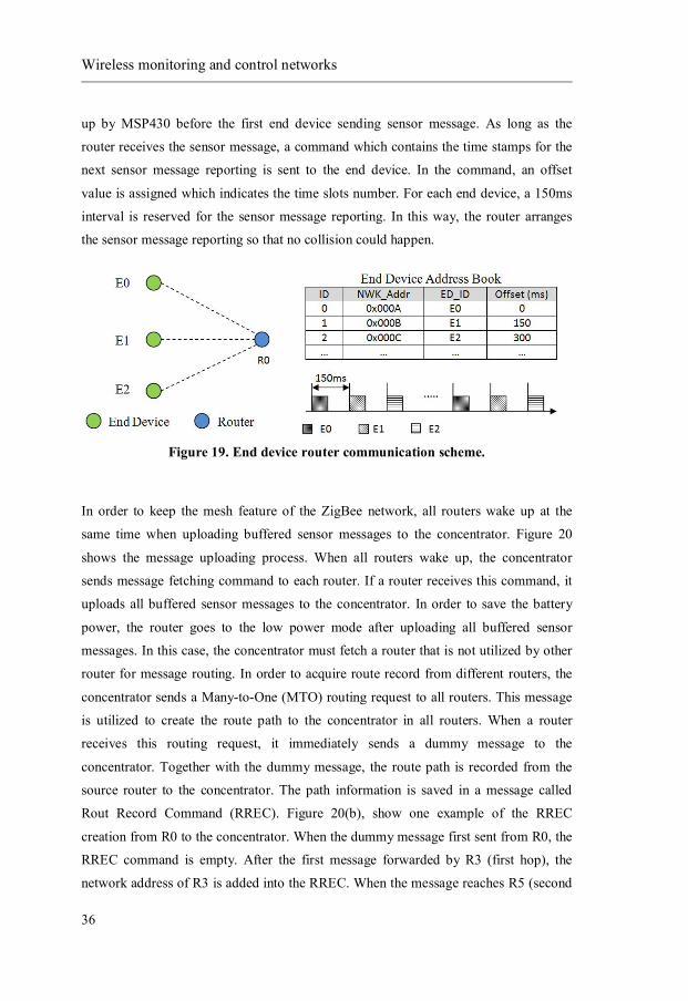
Wireless monitoring and control networks
36
up by MSP430 before the first end device sending sensor message. As long as the
router receives the sensor message, a command which contains the time stamps for the
next sensor message reporting is sent to the end device. In the command, an offset
value is assigned which indicates the time slots number. For each end device, a 150ms
interval is reserved for the sensor message reporting. In this way, the router arranges
the sensor message reporting so that no collision could happen.
Figure 19. End device router communication scheme.
In order to keep the mesh feature of the ZigBee network, all routers wake up at the
same time when uploading buffered sensor messages to the concentrator. Figure 20
shows the message uploading process. When all routers wake up, the concentrator
sends message fetching command to each router. If a router receives this command, it
uploads all buffered sensor messages to the concentrator. In order to save the battery
power, the router goes to the low power mode after uploading all buffered sensor
messages. In this case, the concentrator must fetch a router that is not utilized by other
router for message routing. In order to acquire route record from different routers, the
concentrator sends a Many-to-One (MTO) routing request to all routers. This message
is utilized to create the route path to the concentrator in all routers. When a router
receives this routing request, it immediately sends a dummy message to the
concentrator. Together with the dummy message, the route path is recorded from the
source router to the concentrator. The path information is saved in a message called
Rout Record Command (RREC). Figure 20(b), show one example of the RREC
creation from R0 to the concentrator. When the dummy message first sent from R0, the
RREC command is empty. After the first message forwarded by R3 (first hop), the
network address of R3 is added into the RREC. When the message reaches R5 (second

Remote Monitoring and Control System
37
hop), the network address of R5 is added into the RREC. The RREC message from
each router is saved in the concentrator in the Concentrator Route Relay Table as
shown in Figure 20(c). The algorithm that calculates the router message fetching
sequence is developed as shown in Figure 20(d).
Figure 20. Router – concentrator communication scheme.
The algorithm keeps going through the Concentrator Route Relay Table. The table is
scanned row by row in order to find one router whose network address is not included
in the Route Relay List of any other routers (find the route independent router). Once
the router is found, the corresponding record is removed from the Concentrator Route
Relay Table. The selected router address is appended in the Router message fetching
sequence array (shown in Figure 20(e)). The program keeps going through the table
until the table is empty. This procedure is done every time before the concentrator
starts the sensor message fetching from routers. Although this method introduces a

Wireless monitoring and control networks
38
little overhead, it guarantees the concentrator to utilize the up-to-date routing
information to fetch the message from different routers every time.
4.2 Local manager
In the remote monitoring and control system, a local manager mainly plays three roles,
the message bridge between wireless sensor networks and the web service, the warning
message generator and the logic center of the wireless control network. As a message
bridge, the local manager communicates with the WSN concentrator via the USB port,
as shown in Figure 21. Meanwhile, the local manager also communicates with the web
service via the Internet. In the warning function, sensor messages received by the local
manager are checked against predefined sensor value thresholds. If a sensor message
value is outside the configured threshold, the local manager generates a sensor warning
message. The local manager also keeps track of the communication status of all
wireless devices in the WSN. If no message update received from a wireless device for
long time, a device offline warning is generated by the local manager. In the control
function, the local manager works as the brain for the indoor climate control in a
cultural building. The local manager synchronizes the building climate setting with the
web service all the time. Different control algorithms are implemented in the local
manager as well. For a local wireless control system, the local manager maintains all
controller related configurations. The control commands are sent to different wireless
controllers periodically based on the feedback sensor readings. Additionally, the
wireless control function is implemented with control reliability enhancement.

Remote Monitoring and Control System
39
Figure 21. Local manager communicate with concentrator via USB port.
The local manager software is implemented as a Windows program based on Microsoft
Foundation Class (MFC) [67]. This solution is developed aiming at fast prototyping
and prove of concept. More than often, the Windows operating system has been
criticized by stability problems when utilized in long term maintenance-free
applications. In this case, an embedded PC running a Linux operating system could be
a better choice. Compared with Windows system, the Linux system requires much
lower hardware profile. Enormous open source projects based on Linux provide a huge
resource library on function development. Moreover, the Linux system can be
explicitly tailored according to the user requirement. Nevertheless, one advantage of
the Windows-based local manager is that the local manager software can be installed in
the existing computers of the cultural buildings since the Windows operating system is
still the major operating system utilized.
4.2.1 Local manager software architecture
The software architecture is shown in Figure 22. The Serial Port Manager handles
serial port communication between the concentrator and the local manager. The Data-
Command Synchronizer maintains a two-way data channel between the local manager
and the web service. It helps the local manager forwarding the sensor message to the
web service. It also helps the local manager to udpate climate setting from the web

Local manager
40
service. The Database Worker component provides database service via ODBC
interfaces [67]. Instead of configuration files which are commonly utilized for message
recording, a MySQL [68] database is installed in the local manager. This is due to the
fact that the local manager is designed to maintain large data and relatively complicated
data relationships. A detailed description of the local manager control function
database design is presented in section 4.2.3. The Message Broker layer manages all
messages related issues in the local manager. The String Parser component forwards
the message to the correct component according to the message header. The Device
Status List component records the device communication status. The Message Buffer
component buffers all messages to the web service if the Internet of the local manager
is down. Different application functions are developed based on this infrastructure. At
the moment, the monitoring function, warning function and control function are
implemented in the local manager.
Figure 22. Local manager software architecture.
4.2.2 Monitoring and warning function
The logic of the monitoring function implementation in the local manager is very
straightforward. If a sensor message is received from the Serial Port Monitor
Local Manager
Serial Port Manager Data-Command Synchronizer
Database Worker
Message Broker
String Parser Dev ice Status List Message Buffer
Monitoring Function Warning function Control Function

Remote Monitoring and Control System
41
component, the local manager forwards the received sensor message to the web service
via the Data-Command Synchronizer component. The received sensor message is also
saved in the local manager database. Compared with the web service user interface, the
local manager also provides a data representation function for end devices in the local
wireless sensor network. Figure 23 shows the local manager user interface which
displays the collected sensor data in different curves.
Figure 23. Local manager data monitoring user interface.
By reusing the measured sensor data, a warning function is developed in the local
manager. Measured sensor data and wireless device communication status are under
surveillance by the local manager. The generated warning messages are sent from the
local manager to the web service. Generally, the warning function generates two kinds
of warning messages. Firstly, the warning function checks every received sensor value
against the sensor threshold. If the sensor value is outside the threshold, a sensor
warning message is generated. Secondly, the warning function keeps track of the
network status of all wireless devices in the WSN. If the local manager does not
receive any status update from a device, after a predefined interval, this device is
considered as offline. A device offline warning message is generated. All generated
warning messages are forwarded from the local manager to the web service via the

Local manager
42
Data-Command Synchronizer component. The warning function message flow is
shown in Figure 24.
Figure 24. Local manager monitoring and warning function message flow.
During the local manager startup, the warning function updates the end device
threshold configuration from the web service. A SensorConfigReq request is sent from
the Warning Function module to the web service via the Data Command Synchronizer
module. The sensor configuration from web service is reported to the warning function
in the SensorConfigRsp message. Additionally, if the sensor configuration is updated
during the local manager execution, the sensor configuration update is notified by the
Data-Command Synchronizer module via the SensorConfigUpdate command.
If the local manager receives a sensor message via the Serial Port Monitor module, the
corresponding end device status is updated in the Device Status List. The sensor
message is then checked with the sensor configuration recorded in the warning function.
If the sensor information is outside the sensor threshold configuration, the local
manager generates a sensor message warning.
The Device Status List records the latest message report time for all devices in the
WSN. The end device status is updated every time when the local manager receives the
Serial Port Monitor Device Status List Warning Function Data CommandSynchronizer
SensorConfigReq(BuildingID)
SensorConfigRsp()
SensorConfigUpdate()SensorMessage(SensorID, SensorInfo)
UpdateStatus(SensorID)
SensorMessage(SensorID,SensorIndo) MessageValueCheck(SensorInfo)
RouterHeartBeatMsg(RouterID)SensorMessage(SensorID, SensorInfo)
UpdateStatus(RouterID) SensorWarningMessage(SensorID)
DeviceStatusReq()
DeviceStatusRsp(Offl ineDeviceList)
DeviceStatusWaning()

Remote Monitoring and Control System
43
sensor message. For routers and controller nodes, the time of the heart-beat message
received by the local manager is recorded. The Warning Function module checks the
device status by sending DeviceStatusReq request. On receiving this request, the
Device Status List module check the device report time against the current timestamp.
If the time difference is larger than the predefined interval, the device is considered as
offline. The offline device list is sent to the Warning Function module and forwarded to
the web service.
4.2.3 Control function
The control function is designed aiming at controlling the indoor climate of the
occasionally used churches. Different from the city area, around 50% of the
occasionally used churches do not have a stable Internet connection. This requires that
the wireless control system can work independent of the web service. For a wireless
control system deployed in a cultural building, the local manager contains all logics to
manipulate the local system. In order to get the climate setting, the local manager
synchronizes data with the web service all the time. The indoor climate control is
separated into task control and basic control. In the task control, the indoor climate is
adjusted according to the setting during the human activity schedule. During the time
when no activity is scheduled, the indoor climate is controlled according to the basic
control. The basic control indoor climate configuration is done by the cultural heritage
preservation expert. It is the minimum climate requirement for heritage preservation.
The major goal for the heritage preservation inside churches is to prevent biological
degradation such as mold and insects. In such a case, the temperature and relative
humidity are the two most important factors to be manipulated.
In the local manager function implementation, the database is utilized to maintain the
controller configurations and relationships. Firstly, the local manager maintains the
binding relationship between end devices and wireless control nodes. When an end
device is bound with a control node, the control node adjusts the indoor climate
according to the sensor information reported from the binding end device. Secondly,
the local manager maintains the controller type. The controller type is virtually
configured to the wireless control node by the local manager. It can be changed at any
time without reprogramming the firmware of the wireless control node. Thirdly,

Local manager
44
different control algorithms are implemented for the wireless control node. Same as the
controller type, the control algorithms are also executed and assigned to different
wireless control node virtually in the local manager. In order to achieve different
control effects, a controller can choose the control algorithm from threshold control,
Proportional-Integral-Derivative (PID) control [69] or mold prevention control.
Figure 25 shows the control function database design of the local manager. The control
function information is saved in 7 database tables. Table Router List and Sensor List
maintain the device information of the wireless sensor network. The Binding
Relationship table maintains the relationship between feedback end devices and
wireless control nodes. In order to increase the reliability, one controller is always
bound with more than one feedback end device. For one wireless control node, the
bound end devices are configured with priorities. The Priority field tells the local
manager which sensor message feedback should be applied for the wireless control
node. The table Controller Type contains a list of all possible controller types in the
system. The table Controller Information maintains the configurations of all wireless
control nodes. The Router ID field refers to the router index in the Router List table. It
states which router is programmed as a wireless control node. The Controller Type
field refers to the index of the table Controller Type. It shows the controller type that is
connected with the wireless controller. The Controller Status files record the current
ON/OFF status of the wireless controller. The status is updated based on the
acknowledgement reported from the wireless control node. The Control Algorithm
filed indicates the control algorithm configured for the wireless control node. The
climate control schedules are saved in table Controller Schedule and Default Schedule.
The Controller Schedule table saves all the user issued climate settings for human
activities. Such messages are synchronized from the web service by the local manager
all the time. The Default Schedule table saves the default configurations for the basic
control. It is the climate configuration for heritage preservation purpose.

Remote Monitoring and Control System
45
Figure 25. Control function databse design.
As the logic center for a local wireless control system, the local manager generates
control commands to each wireless control node. The control command generation
process is always triggered by the received sensor message. Once a sensor message is
received, the local manager checks the database and gets the bound control node list.
According to the binding configuration, more than one wireless controller might bind
with one feedback sensor at the same time. Control commands are generated for each
wireless control node based on the climate setting, the sensor value and the control
logic. The control command creation process is described in the state machine as
shown in Figure 26. After start-up, the local manager stays at the IDLE state. Once a
sensor message is received, the local manager forwards the message to the web service
and jumps to the SYNC state. In this state, the local manager checks the Binding
Relationship table to get the binding controller list. If no control node is found, the
local manager jumps back to the IDLE state and wait for the next sensor message.
Otherwise, the local manager jumps to the CONTROLLR PENDING state. For each
bound control node, the local manager generates the specific control command in the
CONTROL PROCESS state. When the control command is generated, the local

Local manager
46
manager jumps back to the CONTROLLER PENDING state. If there is no more
pending control nodes, the local manager jumps to the IDLE state and waits for the
next sensor message.
Figure 26. Control command creation state machine.
For each wireless control node, the control command is generated by the local manager
in the CONTROL PROCESS state. As shown in Figure 27, when local manager enters
this state, the control function component first gets the controller configuration from
the table Controller Information according to the device ID. The controller information
contains the controller type, the controller status and the controller algorithm. Secondly,
the control function component gets the correct schedule from the Controller Schedule
table. It contains the current climate setting. After getting all necessary input
information, the control function component sends the Get Control Command request
to the Controller Algorithm component. Based on the received information, the
controller algorithm returns the Control Command with a Turn-on Interval value.
When receiving this command, the local manager forwards this command to the
corresponding wireless controller node via the concentrator.
IDLE
SYNC
CONTROL PROCESS
CONTROLLER PENDING
[PendingListEmpty]
[ControllerPending]
/UpdatePendingControllerList
[ControlResult]
/GenetateControllerList
[NotFeedBackSensor]
[IsFeedBackSensor]
[SensorMessageReceived]

Remote Monitoring and Control System
47
Figure 27. Local manager control function generation message flow.
4.2.4 Control algorithm implementation
Three control algorithms are implemented in the local manager control function, which
are the threshold control algorithm, mold prevention algorithm and PID algorithm. The
threshold algorithm controls the indoor climate within a certain range. This algorithm
changes the indoor climate to the configured setting as soon as possible. The mold
prevention algorithm calculates the mold risk-free relative humidity level based on the
current temperature. This algorithm is mainly utilized for heritage preservation purpose.
The PID control algorithm is implemented to minimize the overshoot during the indoor
climate control. With careful parameter tuning, the PID algorithm can also eliminate
the climate fluctuation which can cause an uncomfortable feeling during human
activities. All developed control algorithms can be applied for both temperature control
and relative humidity control.
Figure 28 shows an example of temperature threshold control algorithm. The indoor
temperature threshold is set between 9 to 11 °C. When the temperature is higher than
the upper limit, the radiator is turned off. When the temperature is lower than the lower
limit, the radiator is turned on. If the measured temperature is inside the threshold, the
radiator keeps the previous operation. For example, if the temperature goes into the
threshold from a higher temperature, the radiator is turned off within the threshold.
ControlFunction ControllerInformation
Control lerSchedule ControllerAlgori thm
GetControllerInformation()
ControllerInformation()
GetSchedule ()
CurrentSchedule()
GetControlCommand(Control lerID, ControllerType, Control lerSchedule, Controller Algorithm)
ControlCommand(TurnOn Value)
RepackAndSendControlCommand()

Local manager
48
Otherwise, the radiator is turned on within the threshold. The purpose of the threshold
definition is to prevent the frequently switching on/off of the mechanical power relay.
However, large threshold also introduce big temperature change which is not good for
the heritage preservation. By default, the threshold is defined as 2 °C. Users can change
the configuration according to the specific requirement.
Figure 28. Temperature threshold control algorithm.
A relative humidity control result is shown in Figure 29. In this figure, both the upper
and low thresholds are set to 64 %. As shown from the curve, the relative humidity
jumps between the settings point all the time.
Figure 29. Relative humidity threshold control result.

Remote Monitoring and Control System
49
Figure 30 shows the mold prevention control algorithm. The mold risk-free relative
humidity is calculated based on the current indoor temperature according to Eq.1 [70].
푅퐻 = 75 + 20 × 푒( . × ) (1)
In the mode prevention control algorithm, the target climate setting is dynamically
calculated. For a wireless radiator controller, the target temperature is calculated based
on the current relative humidity. For a wireless dehumidifier, the target relative
humidity is calculated based on the current temperature. The curve indicates the
boundary of the mold risk. The red dot indicates the climate with mold risk while the
green dots indicate the climates which are mold risk free.
Figure 30. Mold prevention contorl algorithm.
As described in the threshold control algorithm and the mold prevention control
algorithm, the wireless control nodes keep working until the feedback sensor value
reach the target setting. Such control methods bring climate control overshoots whose
amplitude depends on the climate change delay time. Moreover, when the system
reaches the target setting, the system stops working until the climate is outside the
defined threshold. As a result, the control system generates a lot of climate fluctuation
near the setting point. Such fluctuation is not only harmful to the cultural heritage, but

Local manager
50
also, when it is large enough, makes people uncomfortable [71]. In order to reduce the
fluctuations, the PID control algorithm, as shown in Eq.2, is implemented in the local
manager. In the PID control algorithm, the control device is turned on only for a certain
percentage according to the PID calculation. Obviously, the PID control algorithm
introduces more power switching into the control device. The solid-state power switch
is recommended when utilizing PID control algorithm.
Where Kp - Proportional gain, a tuning parameter Ki - Integral gain, a tuning parameter Kd - Derivative gain, a tuning parameter e - Error t - Time or instantaneous time (the present) τ- Variable of integration; takes on values from time 0 to the present t Figure 31 shows an indoor climate PID control result. The room temperature is
configured to 21 °C between 7:30 AM to 17:00 PM. The rest time the temperature is
set to 19 °C. The radiator temperature setting changed from 19 °C to 21 °C at time 7:30
AM. After 30 minutes, the temperature researched around 20.3 °C. Then, the
temperature slowly approached 21 °C until 17:00 PM. For different control buildings,
users can configure the Kp, Ki and Kd value in Eq.2 to reach different control effects.
Figure 31. Indoor temperature PID control result.
7:30 am

Remote Monitoring and Control System
51
4.3 Web service The web service provides web-based user interface for the remote monitoring and
control system. The web service also provides interfaces of message uploading and
downloading for different local managers. Figure 32 shows the web service
architecture. The web-service is developed based on the LAMP (Linux + Apache +
MySQL + PHP [72]) server. Since the whole web service is executed passively
(execute upon invocation), the CRON service of Linux is utilized to execute time-based
schedules, for example, local manager status check. The user interfaces for different
functions are developed in Monitoring User Interface (UI), Control UI and Warning UI
accordingly. Moreover, a component named “Data Command Synchronizer” is
implemented to provide data exchange service for all local managers.
Figure 32. Web service architecture.
The Data Command Synchronizer provides two-way communication interfaces with
local managers. The interface can be categorized into “message upload” interfaces,
“message download” interfaces and “message update” interfaces. The message upload
interfaces allow local managers to upload information to the web service, i.e., received
sensor messages and generated warning messages. The message download interfaces
allow local managers to download WSN configurations from the web service, for
example, wireless control node configuration, sensor interval configuration, climate
settings and so on. The message download interfaces are usually invoked during the
local manager startup. The message update interfaces forward the web service updating
Linux
Apache MySQL PHP CRON
WebServ ice
Data Command Synchronizer
Monitoring UI Control UI Warning UI

Web service
52
to local managers. For example, a sensor threshold configuration is updated in the web
service side by the remote user. Such configuration update is notified by this interface
to the local manager that the WSN contains the end device.
The user interface of the remote monitoring represents the measured sensor data in
curve format. Figure 33 shows the remote monitoring result of one cultural building.
The floor plan of the building is shown in the left side. If a building contains more than
one floor, users can upload multiple floor plans in the administration pages according
to the building construction. The rough location of the end devices are marked in the
floor plan. By clicking the end device in the floor plan, the corresponding curve is
shown in the diagram to the right. Multiple curves can be shown in the same curve
diagram with different colors. The interval of the curve can be changed according to
the user configuration. Moreover, the same graph can also be utilized to compare the
sensor information from other buildings.

Remote Monitoring and Control System
53
Figu
re 3
3. R
emot
e m
onito
ring
func
tion
web
use
r in
terf
ace.

Web service
54
The control function user interface is shown in Figure 34. This page can only be
utilized by authorized users. In this page, users can issue climate setting to control the
indoor climate in different locations. Figure 34 shows the user interface of adding an
activity in a church. The sketch of the church is shown in the left side of the web page.
The rough location of the wireless controller is shown in the sketch as well. The
configuration interface is shown on the right side. To configure one schedule, users
need to select the start date, start time and end time of the schedule. Moreover, users
can also configure the command type as daily, weekly, monthly or yearly. The
temperature setting is configured in the Set and execute frame according to the
controller type. For a radiator, the temperature is configured. For a dehumidifier, the
relative humidity is configured.
Figure 34. Control function user interface.

Result
55
5 Result
This dissertation presents a remote wireless monitoring and control solution for cultural
heritage preservation purpose. The system consists of three parts, i.e., the wireless
sensor network part, the local manager part and the web service part. For each cultural
building, a wireless sensor network and a local manager is installed. All local managers
communicate with the web service via the Internet.
The ZigBee protocol is utilized in the wireless sensor network part. The performance of
the ZigBee network is improved in order to meet the cultural heritage preservation
requirements. Specifically, ZigBee routers keep checking the communication link to
the concentrator. Once the communication problem detected, the ZigBee router notifies
the problem to its child-nodes. On the other hand, the ZigBee end device keeps
checking the communication status of its parent device. The end device rejoins the
network if the current parent device cannot repair the communication link with the
concentrator. During the time when the end device lost the communication with the
concentrator, the measured sensor data are buffered in the end device. The buffered
senor messages are uploaded to the concentrator when the communication link is
reestablished. The wireless sensor network performance improvement is designed in
different state machines. In the end device state machine, the battery-driven end device
is set to sleep mode as much as possible. An end device powered by a 1.2 Ah battery
with 15 minute sensor report interval can work 10 years. The wireless sensor network
monitoring and control function are developed based on the ZigBee protocol with
improved performance.

Result
56
Moreover, a truly battery-driven ZigBee sensor network for wireless monitoring
function is developed. An extra microprocessor is utilized as switch to control the
power of the ZigBee router. The senor message forwarding process is separated into
two steps. In the first step, sensor message reporting from different end devices are
scheduled in different time slot. Each end device is assigned with a separated time slot
to report the measured sensor data to the router. In the second step, all ZigBee routers
wake up at the same time. The concentrator fetches the buffer sensor messages from
routers according to the network route. This design eliminates the ZigBee router
dependency of the power outlet. The battery-driven router can have at least 1 year
battery lifetime when working in a WSN with 50 end devices with 15 minutes sensor
message report interval.
The local manager establishes the communication between wireless sensor networks
and the web service. In the monitoring function, the local manager forwards the
received sensor data to the web service. In the warning function, the web service keeps
synchronizing the sensor threshold configuration between the web services. The sensor
message warning and device offline warning are generated and forwarded to the web
service. The local manager also works as the logic center for the control function. The
indoor climate settings are updated from the local manager from the web service.
Different control algorithms are implemented in the local manager. The security issues
are highly considered in the control function implementation. If the wireless controller
lost the communication, no further control can be made before the communication is
repaired.
The web service provides user interface for the remote monitoring and control
functions. Measured sensor data are presented in curve format. Authorized users could
also remote control the indoor climate of different cultural buildings. On the other side,
the web service also provides data exchange service with all local managers for
message uploading and downloading.
Till today, the developed system has been deployed around 30 places in Sweden and
Norway. The system was nominated by the Swedish Embedded Award 2010 and been
demonstrated at the Scandinavia Embedded Conference 2010 in Stockholm.

Summary of the Included Papers
57
6 Summary of the Included Papers
Paper 1
Remote Sensing System for Cultural Buildings Utilizing ZigBee Technology by
Jingcheng Zhang, Allan Huynh, Qin-Zhong Ye and Shaofang Gong, Proceedings of
the 8th International Conference on Computing, Communications and Control
Technologies (CCCT 2010), Orlando, USA, pp. 71-77, April 2010.
This paper presents a wireless remote monitoring system using the ZigBee standard.
This system is a wireless solution for monitoring purpose in cultural buildings in order
to protect cultural heritage. The concept of this system utilizes the ZigBee network
protocol to carry and transmit data collected by sensors and store them into both local
and remote databases. Thus, users can monitor the measured data locally or remotely.
Especially, the power consumption is optimized to extend the lifetime of the battery-
driven devices. Moreover, since the system has a modular architecture, it is easy to add
extra services into this system.
Author’s contribution:
The author proposed the system architecture, designed and implemented the methods
described in this work, set-up and performed the test and wrote the article.

Summary of the Included Papers
58
Paper 2
Design of the Remote Climate Control System for Cultural Buildings Utilizing ZigBee Technology by Jingcheng Zhang, Allan Huynh, Qin-Zhong Ye and Shaofang
Gong, Sensors & Transducers Journal (ISSN 1726-5479), Vol. 118, Issue 7, pp. 13-27,
July 2010.
A wireless solution of remote climate control for cultural buildings is presented in this
paper. The system allows users to use web service to control indoor climate in different
cultural buildings, like churches. The wireless sensor networks deployed in churches
receive the control commands and manage the indoor climate. The whole system is
modularly designed, which makes possible an easy service extension, system
reconfiguration and modification. This paper includes the system overview and the
software design of each part within the system.
Author’s contribution:
The author proposed the system architecture of the remote control system, designed
and implemented the message communication of the system and wrote the article.
Paper 3
Reliability and Latency Enhancements in a ZigBee Remote Sensing System by
Jingcheng Zhang, Allan Huynh, Qin-Zhong Ye and Shaofang Gong, Proceedings of 4th
International Conference on Sensor Technologies and Applications (SENSORCOMM
2010), Venice/Mestre, Italy, pp. 196-202, July 2010.
This paper presents the methods to improve the reliability and optimize the system
latency of the remote sensing system. The concept of this system utilizes the ZigBee
network protocol to transmit sensor information and process them at both local and
remote databases. The enhancement has been done in different parts in this system. In
the ZigBee network part, the network topology is configured and controlled. The
latency for message transmitting is also optimized. In the data processing part, the
network status check function and data buffer function are introduced to improve the

Summary of the Included Papers
59
system reliability. Additionally, the system latency is measured to compare with the
Ad-hoc On Demand Distance Vector (AODV) algorithm used in the ZigBee standard.
Author’s contribution:
The author proposed the idea of reliability and latency enhancement in a wireless
sensor network, designed and implemented the methods described in this work, set-up
and performed the test and wrote the article.
Paper 4
A Fully Wireless Monitoring and Control System for Protecting Cultural Heritage
by Jingcheng Zhang, Allan Huynh, Qin-Zhong Ye and Shaofang Gong, Proceedings of
20th IEEE International Conference on Collaboration Technologies and Infrastructures,
Paris, France, pp. 51-57, June 2011.
This paper presents a component-based wireless monitoring and control system. The
system is introduced from both the system architecture and function point of view. The
paper begins with the introduction of the component design and the communication
interaction between them. The system is composed of three components, i.e., the
wireless sensor network, the local server and the main server. Wireless sensor networks
are deployed in different locations for remote monitoring and control purposes. The
monitoring results and control commands are synchronized between the main server
and wireless sensor networks via local servers. The test results of the battery lifetime
calculation and remote monitoring field test results are presented at the end of the paper.
Author’s contribution:
The author proposed and developed the system architecture of a remote monitoring and
control system, designed and implemented the methods described in this work, set-up
and performed the test and wrote the article.

Summary of the Included Papers
60
Paper 5
A Communication Reliability Enhancement Framework for the ZigBee Wireless Sensor Network by Jingcheng Zhang, Allan Huynh, Qin-Zhong Ye and Shaofang
Gong, Sensors & Transducers Journal (ISSN 1726-5479), Vol.135, Issue 12, pp. 42-56.
2012.
This paper presents the framework that enhances the communication reliability of
wireless sensor network using the ZigBee protocol. The paper begins with the
introduction of common communication problems caused by broken links between the
sensor module and the message relay, or between different message-relays. Extra
message handshake mechanisms are added to solve the mentioned problems. Based on
the solution to different problems, a general purpose reliability enhancement
framework is developed. The framework contains two state machines for both the
sensor module and the massage relay. These two state machines can work together with
the ZigBee protocol to enhance the network communication reliability. Moreover, the
battery lifetime of the sensor module under link loss is considerably increased after the
enhancement.
Author’s contribution:
The author investigated the limitation of ZigBee wireless sensor network, proposed the
idea of the reliability enhancement, designed, developed and verified the methods
described in this work, set-up and preformed the power consumption test and wrote the
article.
Paper 6
A Web-based Remote Indoor Climate Control System Based on Wireless Sensor
Network by Jingcheng Zhang, Allan Huynh, Qin-Zhong Ye and Shaofang Gong,
International Journal of Sensors and Sensor Networks, Vol. 1, No. 3, June 2013.
This paper presents the design and implementation of a web-based wireless indoor
climate control system. The user interface of the system is implemented as a web
service. People can login to the website and remotely control the indoor climate of

Summary of the Included Papers
61
different locations. A wireless sensor network is deployed in each location to execute
control commands. A gateway is implemented to synchronize the information between
the wireless sensor network and the web service. The gateway software also includes
scheduling function and different control algorithms to improve the control result.
Additionally, the system security and availability are highly considered in this system.
The gateway software implements a warning function which sends warning messages
when emergency happens. Finally, the whole wireless control system architecture is
modularly designed. It is easy to add different control applications or different control
algorithms into the system.
Author’s contribution:
The author studied the requirement of indoor climate control for cultural heritage
buildings, proposed the idea of the wireless remote control system, developed the
control system architecture, investigated, developed and compared the effects of
different control algorithms on cultural heritage building indoor climate control.
Paper 7
Design and Implementation of a Truly Battery-Driven ZigBee Wireless Sensor Network by Jingcheng Zhang, Qin-Zhong Ye, Allan Huynh and Shaofang Gong,
Manuscript, September, 2013.
This paper presents the design and implementation of a ZigBee wireless sensor
network using battery-driven routers. In order to save the power of the ZigBee router,
another microprocessor is utilized as the synchronization controller which controls the
power of the ZigBee router according to the wireless sensor network applications. The
battery provides power for both ZigBee router and microprocessor. The microprocessor
maintains the time of the wireless sensor network applications when the router is
powered off. The power is only turned on before the router needs to execute the
scheduled application. The wireless sensor network is established by three kinds of
wireless devices: the concentrator, the router and the end device. The concentrator
configures the wireless sensor network during the network installation. Periodically,
the concentrator sends sensor message query to each router in order to collect buffered
sensor messages. The router communicates with both end devices and the concentrator.

Summary of the Included Papers
62
The router controls the sensor message report interval of the end device. The router
also buffers the sensor messages reported from end devices. For the concentrator, the
router uploads buffered sensor messages to the concentrator periodically. The wireless
sensor network is optimized from both the collision avoidance and battery lifetime
point of view. In order to reduce the message collision, the concentrator allocates a
time window for each router. End devices associated with one router are configured to
send sensor messages only during the specified time window. Furthermore, the router
also controls the sensor report time for each end device. The given time window is
separated into many time slots. End devices are configured to report sensor message in
different time slots. In order to optimize the router power consumption, an algorithm is
developed in the concentrator to determine the sensor message fetching sequence to
each router. If a router is not utilized as message relays for other routers, the sensor
message from this router is firstly fetched by the concentrator. In this way, the router
can go to power off mode right after the message uploading. Additionally, stability
enhancement state machines are developed for both router and end device. They help
router and end devices to re-establish the communication with the wireless sensor
network with battery-powered routers. Finally, the power consumption and battery
lifetime is calculated at the end of the paper.
Author’s contribution:
The author proposed the idea, designed and implemented the methods described in this
work, set-up and perform the power consumption test and wrote the manuscript.

Bibliography
63
BIBLIOGRAPHY [1] Atzori L, Iera A. and Morabito G, “SIoT: Giving a Social Structure to the
Internet of Things” IEEE Communications Letters, Vol 15, Issue 11, pp. 193-
1195.
[2] Mandrioli Paolo, Caneva Giulia and Sabbioni Cristina, Cultural Heritage and
Aerobiology: Methods and Measurement Techniques for Biodeterioration
Monitoring, 2004 Edition, Springer, 2003, pp.47-59.
[3] Drew Gislason, ZigBee Wireless Networking, Newnes, 2008, pp7.
[4] Mailadil T. Sebastian, Dielectric Materials for Wireless Communication, 1st
Edition, Elsevier Science, 2008, pp.33-39.
[5] Miyamoto A, Watanabe K and Ikeda K, “Packet loss rate estimation with active
and passive measurements” 2012 Asia-Pacific Signal & Information
Processing Association Annual Summit and Conference (APSIPA ASC),
[6] Poul Klenz Larsen, Magnus Wessberg and Tor Broström, “Adaptive ventilation
for occasionally used churches” 3rd European Workshop on Cultural Heritage
Preservation, Bolzano, Italy, Sep.16-18, 2013.
[7] W. J. Kowalski, “Indoor Mold Growth - Health hazards and remediation”,
HPAC Engineering, Sep, 2000.
[8] Seth Blumsack, Alisha Fernandez, “Ready or not, here comes the smart grid!”
Energy, Volume 37, Issue 1, January 2012, pp. 61–68.
[9] McDaniel, P and McLaughlin, S. “Security and Privacy Challenges in the
Smart Grid”, IEEE Security & Privacy, Volume 7, Issue 3, , pp.75-77, 2009.
[10] V. K. Sood, D. Fischer, J. M. Eklund and T. Brown, “Developing a
communication infrastructure for the Smart Grid”, 2009 IEEE Electrical Power
& Energy Conference (EPEC), Montreal, pp1-7, 2009.

Bibliography
64
[11] A. Zaballos, A. Vallejo and J. M. Selga, “Heterogeneous communication
architecture for the smart grid”, IEEE Network, Volume 25, Issue 5, pp30-37,
2011.
[12] Luigi Atzori, Antonio Iera and Giacomo Morabitoc, “The Internet of Things: A
survey”, Computer Networks, Vol 54, Issue 15, pp2787-2805, 2010.
[13] Friedemann Mattern and Christian Floerkemeier, “From the Internet of
Computers to the Internet of Things”, LNCS, Vol 6462, pp242-259, 2010.
[14] G. Mulligan, “The internet of things: Here now and coming soon.” IEEE
Internet Compute, Volumn 14, Issue 1, pp35-36, 2010.
[15] Siok Kheng Tan, Mahesh Sooriyabandara, and Zhong Fan, “M2M
Communications in the Smart Grid: Applications, Standards, Enabling
Technologies, and Research Challenges”, International Journal of Digital
Multimedia Broadcasting, Volume 2011, 2011.
[16] Geng Wu, Talwar, S, Johnsson, K and Himayat, N, “M2M: From mobile to
embedded internet”, IEEE Communications Magazine, Volume 49 , Issue 4,
pp36-43, 2011.
[17] Niyato, D. Lu Xiao and Ping Wang, “Machine-to-machine communications for
home energy management system in smart grid”, IEEE Communications
Magazine, Volume 49, Issue 4, pp53-59, 2011.
[18] S. Kim, S Pakzad, D Culler, J Demmel, G Fenves, S Glaser and M. Turon,
“Health monitoring of civil infrastructures using wireless sensor networks”, 6th
Int. Conf. on Information Processing in Sensor Networks (IPSN), 2007.
[19] K. Chintalapudi, T. Fu, J. Paek, N. Kothari, S. Rangwala, J. Caffrey, R.
Govindan, E. Johnson, and S. Masri, “Monitoring civil structures with a
wireless sensor network” Internet Computing, Vol 10, Issue 2, 2006.

Bibliography
65
[20] J. P. Lynch and K. J. Loh, “A summary review of wireless sensors and sensor
networks for structural health monitoring” Shock and Vibration Digest, Mar
2006.
[21] O. Gnawali, K. Jang, J. Paek, M. Vieira, R. Govindan, B. Greenstein, A. Joki,
D. Estrin, and E. Kohler, “The Tenet architecture for tiered sensor networks”
4th International conference on Embedded Networked Sensor Systems
(SENSYS), 2006.
[22] N. Xu, S. Rangwala, K. Chintalapudi, D. Ganesan, A. Broad, R. Govindan, and
D. Estrin, “A wireless sensor network for structural monitoring” 2nd
International conference on Embedded Networked Sensor Systems (SENSYS),
2004.
[23] K. Chintalapudi, J. Paek, O. Gnawali, T.S. Fu, K. Dantu, J. Caffrey, R.
Govindan, E. Johnson, and S. Masri. “Structural damage detection and
localization using netshm”. 5th International conference on Information
Processing in Sensor Networks (IPSN), 2006.
[24] Matteo Ceriotti1, Luca Mottola1, Gian Pietro Picco, Amy L. Murphy, ¸Stefan
Guna, Michele Corrà, Matteo Pozzi, Daniele Zonta and Paolo Zanon,
“Monitoring Heritage Buildings with Wireless Sensor Networks: The Torre
Aquila Deployment”, 8th ACM/IEEE International conference on Information
Processing in Sensor Networks (IPSN),2009
[25] Abruzzese D, Angelaccio M, Giuliano R and Miccoli L, “Monitoring and
vibration risk assessment in cultural heritage via Wireless Sensors Network”,
2nd Conference on Human System Interactions (HSI '09), pp586-573, 2009.
[26] Abruzzese D, Angelaccio M, Buttarazzi B and Giuliano R, “Long life
monitoring of historical monuments via Wireless Sensors Network”, 6th
International Symposium on Wireless Communication Systems (ISWCS 2009),
pp570-574, 2009.

Bibliography
66
[27] Lee, A.M.C. Angeles, C.T. Talampas, M.C.R and Sison, L.G, “MotesArt:
Wireless Sensor Network for Monitoring Relative Humidity and Temperature
in an Art Gallery”, IEEE International Conference on Networking, Sensing and
Control (ICNSC 2008). pp1263 – 1268, 2008.
[28] Pahuja Roop , Verma H.K and Uddin Moin, “A Wireless Sensor Network for
Greenhouse Climate Control”, IEEE Pervasive Computing, Vol 12, Issue 2,
pp49-58, 2013.
[29] Ahonen T, Virrankoski R and Elmusrati M, “Greenhouse Monitoring with
Wireless Sensor Network”, IEEE/ASME International Conference on
Mechtronic and Embedded Systems and Applications (MESA 2008), pp403-408,
2008.
[30] Al-Karaki, J.N, Ul-Mustafa, R. and Kamal, A.E. “Data aggregation in wireless
sensor networks - exact and approximate algorithms”, 2004. HPSR. 2004
Workshop on High Performance Switching and Routing, Pg 241-245, 2004.
[31] Q. Li, J. Aslam and D. Rus, “Hierarchical power aware routing in sensor
networks”, Proc. DIMACS Workshop, Pervasive Net, May, 2001.
[32] F. Ye, H. Luo, J. Cheng, S. Lu and L. Zhang, “A two-tier data dissemination
model for large-scale wireless sensor networks”, Proceedings of the 8th annual
international conference on Mobile computing and networking, MobiCom '02,
Pages 148-159, 2002.
[33] Milan Lukic, Bogdan Pavkovic, Nathalie Mitton, Ivan Stojmenovic, “Greedy
geographic routing algorithms in a real environment”, The Fifth International
Conference on Mobile Ad-hoc and Sensor Networks, 2009.
[34] Mark A. Perillo and Wendi B. Heinzelman, “Wireless Sensor Network
Protocols”, online resource, University of Rochester Rochester, NY, USA.
[35] Wei Ye, John Heidemann and Deborah Estrin, “Sensor-MAC (S-MAC):
Medium Access Control for Wireless Sensor Networks”, 21st International

Bibliography
67
Annual Joint Conference of the IEEE Computer and Communications Societies
(INFOCOM 2002), New York, NY, USA, June, 2002.
[36] T. van Dam and K. Langendoen, “An adaptive energy-efficient mac protocol
for wireless sensor networks”, In Proceedings of the First ACM Conference on
Embedded Networked Sensor Systems (SenSys), 2003.
[37] G. Lu, B. Krishnamachari, and C. Raghavendra. “An adaptive energy-efficient
and low-latency MAC for data gathering in sensor networks”, In Proceedings
of the Fourth International Workshop on Algorithms for Wireless, Mobile, Ad
Hoc and Sensor Networks (WMAN), 2004.
[38] V. Rajendran, K. Obraczka, and J. Garcia-Luna-Aceves, “Energy-efficient,
collision-free medium access control for wireless sensor networks”, In
Proceedings of the First ACM Conference on Embedded Networked Sensor
Systems (SenSys), 2003.
[39] M. Perillo and W. Heinzelman, “DAPR: A protocol for wireless sensor
networks utilizing an application-based routing cost”, In Proceedings of the
IEEE Wireless Communications and Networking Conference (WCNC), 2004.
[40] W. Heinzelman, J. Kulik, and H. Balakrishnan, “Adaptive protocols for
information dissemination in wireless sensor networks”, In Proceedings of the
Fifth Annual ACM/IEEE International Conference on Mobile Computing and
Networking (MobiCom), 1999.
[41] C. Intanagonwiwat, R. Govindan, and Estrin D, “Directed diffusion: A scalable
and robust communication paradigm for sensor networks”, In Proceedings of
the Sixth Annual International Conference on Mobile Computing and Networks
(MobiCom), 2000.
[42] WirelessHART and HART protocol: online resource http://www.hartcomm.org.
[43] ISA100.11a: online resource www.isa.org/isa100 .

Bibliography
68
[44] C. Perkins, “Ad hoc On-Demand Distance Vector (AODV) Routing”, IETF,
RFC3561, 2003.
[45] DD Falconer, “Time division multiple access methods for wireless personal
communications”, online resource http://www.cs.yale.edu/.
[46] Edsger Dijkstra, Dijkstra's algorithm.
[47] Fiore, Gabriella, Valeria Ercoli, Alf J. Isaksson, Krister Landern, and Maria
Domenica Di Benedetto, “Multi-Hop Multi-Channel Scheduling for Wireless
Control in WirelessHART Networks” in ETFA, 2009.
[48] Deji Chen, Mark Nixon, Aloysius Mok, WirelessHART Real-Time Network for
Industrial Automation, Springer, 2010.
[49] IPv6 over Low-Power WPAN (6lowpan), tools.ietf.org/wg/6lowpan/.
[50] Shelby, Zach, Carsten Bormann, 6LoWPAN: The Wireless Embedded Internet,
Willey, 2009.
[51] IETC RFCs, http://tools.ietf.org/html/rfc2894 .
[52] ISO/IEC standard 7498-1:1994.
[53] ZigBee Alliance, “ZigBee and Wireless Radio Frequency Coexistence”, ZigBee
Alliance Documents, 2007.
[54] Mihaela Cardei, Resource Management in Wireless Networking (Network
Theory and Applications), Springer; 2005 edition, pp265-273.
[55] Institute of Electrical and Electronics Engineers (IEEE 802), Wireless Medium
Access Control (MAC) and Physical Layer (PHY) Specifications for Low-Rate
Wireless Personal Area Networks (LR-WPANs), IEEE Computer Society, 2004.

Bibliography
69
[56] ZigBee Alliance, “ZigBee Application Profiles”, ZigBee Alliance Documents,
2007.
[57] Olga Saukh, Efficient Algorithms for Structuring Wireless Sensor Networks,
Logos Verlag Berlin, 2009.
[58] Communication Electronics Research Group, www.comelec.itn.liu.se/ .
[59] Texas Instrument, www.ti.com.
[60] Allan Huynh, Jingcheng Zhang, Qin-Zhong Ye and Shaofang Gong, “ZigBee
Radio with External Power Amplifier and Low-Noise Amplifier”, Sensors &
Transducers Journal, Vol 118, Issue 7, 2010.
[61] Allan Huynh, Jingcheng Zhang, Qin-Zhong Ye and Shaofang Gong, “ZigBee
Radio with External Low-Noise Amplifier”, Sensors & Transducers Journal,
Vol 114, Issue 3, 2010.
[62] Temperature & Relative Humidity Sensor from Sensirion,
http://www.sensirion.com/en/products/humidity-temperature/humidity-sensor-
sht11/.
[63] John H. Davies, MSP430 Microcontroller Basics, Newnes, Sep, 2008.
[64] Ivan Stojmenovic, Handbook of Sensor Networks: Algorithms and
Architectures, Wiley-Interscience, 1st edition, Oct. 2005, pp251-253.
[65] Unknown-Binding, Wood Preservation Manual, International Book
Distributors, 1994, pp 21-27.
[66] Shahin Farahani, ZigBee Wireless Networks and Transceivers, Newne, Sep.
2008, pp114-118.

Bibliography
70
[67] Stefan Björnander, Microsoft Visual C++ Windows Applications by Example:
Code and explanation for real-world MFC C++ Applications, Packt Publishing
(June 26, 2008).
[68] MySQL database, http://www.mysql.com/.
[69] Guillermo J. Silva, Aniruddha Datta, S. P. Bhattacharyya, PID Controllers for
Time Delay Systems, Birkhäuser, 2005.
[70] W. J. Kowalski, “Indoor Mold Growth - Health hazards and remediation”,
HPAC Engineering, 2000.
[71] Frederrick R, Georgea M, “Thermal comfort during cyclical temperature
functions”, ASHRAE, 1980.
[72] Jason Gerner, Morgan Owens, Elizabeth Naramore and Matt Warden,
Professional LAMP: Linux, Apache, MySQL and PHP5 Web Development,
Wrox, 2005
[73] ZigBee Alliance, www.ZigBee.org
[74] WirelessHart, http://www.hartcomm.org
[75] ISA SP100, http://www.isa.org

Papers
The articles associated with this thesis have been removed for copyright reasons. For more details about these see: http://urn.kb.se/resolve?urn=urn:nbn:se:liu:diva-102593