a report submitted in partial fulfillment of the...
TRANSCRIPT

STUDY ON LIGHTNING PROTECTION FOR PV SYSTEM
MOHD HISANUDDIN BIN ZAMHARIR
A report submitted in partial fulfillment of the requirements for the Degree
of Electrical Engineering (Industrial Power)
Faculty of Electrical Engineering
UNIVERSITI TEKNIKAL MALAYSIA MELAKA
2012

I declare that this report entitle “Study on Lightning Protection for PV System” is the result of
my own research except as cited in references. The report has not been accepted for any
degree and is not concurrently submitted in candidature of any other degree.
Signature : …………..………………………………….
Name : MOHD HISANUDDIN BIN ZAMHARIR
Date : 30𝑡𝑡ℎ June 2012

“I hereby declare that I have read through this report entitle “Study on Lightning Protection
for PV System” and found that it has comply the partial fulfillment for awarding the degree of
Bachelor of Electrical Engineering (Industrial Power)
Signature :…………..………………………………….
Supervisor’s Name : MR. ZIKRI ABADI BIN BAHARUDIN
Date : 30𝑡𝑡ℎ June 2012

iii
ACKNOWLEDGEMENT
I would like to thanks to all individual that has been involved in this project. Great
deals appreciated go to the behalf of university which are Universiti Teknikal Malaysia
Melaka (UTeM) and Faculty of Electrical Engineering specifically for giving me opportunity
to me takes the final year project subject. My grateful thanks also go to Mr. Zikri Abadi Bin
Baharudin, my supervisor for guiding the steps and ideas, for patience and time in guiding me
and all his kindness throughout this semester. Not forget, great appreciation go to Mrs.
Junainah Binti Sardi who help me from time to time during doing this project is in first stage.
Special thanks go to my beloved parents and family members for supporting and encouraging
me to success complete this project. I am also would like to thankful my friends for helping
me in all situation during completion of this project. Last but not least, special
acknowledgment to others, as for journals, conference papers and reports that has been used as
the references throughout this project.

iv
ABSTRACT
This thesis presents the Study on Lightning Protection for PV System. Lightning protection on
photovoltaic system is very important to avoid the effect of the strike damaging the
photovoltaic system. An experiment was set up to study the propagation effect of the induce
voltage to the solar panel by the horizontal discharge which produced by 1.2/50µs lightning
wave shape. The propagation effect of the induce voltage lead to the existence of unwanted
signal which may cause damage to the sensitive device. The experiment was conduct using
impulse voltage generator in high voltage lab to generate impulse voltage. The impulse
voltage was generated to represent 1.2/50µs lightning indirect strike. Source for the
photovoltaic system tested. The experiment strategies are testing the photovoltaic system
without shielded cable and with shielded cable. The main consideration for the parameters of
unwanted signal such as the peak voltage and duration were analyzed. It is found that
maximum voltage of unwanted signal is 1.64kV for unshielded cable. The maximum duration
of unwanted signal is 0.82μs. On the other hand, the maximum voltage and maximum duration
for shield cable are found to be 0.702kV and 0.14μs, respectively. Mean that, for photovoltaic
system with proper shielded to the cable can reduce the unwanted signal effectively by
reducing the peak voltage about 0.938kV while reducing the unwanted signal duration about
0.68μs. This thesis can be guidance to improve the protection system for photovoltaic system
in future.

v
ABSTRAK
Tesis ini membentangkan mengenai Kajian Perlindungan Kilat untuk Sistem PV.
Perlindungan kilat pada sistem fotovoltaik adalah sangat penting untuk mengelakkan kesan
buruk yang merosakkan sistem photovoltaik. Satu eksperimen telah disusun untuk mengkaji
kesan penyebaran voltan teraruh kepada panel solar oleh menunaikan mendatar yang
dihasilkan oleh bentuk gelombang kilat 1.2/50μs. Kesan penyebaran voltan teraruh mendorong
kepada kewujudan isyarat yang tidak diingini yang boleh menyebabkan kerosakan kepada
peranti yang sensitif. Eksperimen ini dijalankan menggunakan penjana voltan dedenyut dalam
makmal voltan tinggi untuk menjana voltan dedenyut. Voltan dedenyut telah dijana untuk
mewakili 1.2/50μs kilat tidak langsung. Sumber untuk sistem photovoltaik diuji. Strategi
eksperimen adalah menguji sistem photovoltaik tanpa kabel berperisai dan dengan kabel
berperisai. Pertimbangan utama bagi parameter isyarat yang tidak diingini seperti voltan
puncak dan tempoh telah dianalisis. Ia didapati bahawa voltan maksimum isyarat yang tidak
diingini ialahi 1.64kV untuk kabel tidak berperisai. Tempoh maksimum isyarat yang tidak
diingini pula adalah 0.82μs. Sebaliknya, voltan maksimum dan tempoh maksimum kabel
berperisai masing-masing adalah 0.702kV dan 0.14μs. Ini bermakna bahawa bagi sistem
photovoltaik dengan melindungi kabel boleh mengurangkan isyarat yang tidak diingini secara
berkesan dengan mengurangkan voltan puncak kira-kira 0.938kV pada masa yang sama
mengurangkan tempoh isyarat yang tidak dikehendaki sehingga 0.68μs. Tesis ini dapat
menjadi panduan untuk memperbaiki sistem perlindungan bagi sistem fotovoltaik dalam masa
akan datang.

vi
TABLE OF CONTENTS
CHAPTER
1
2
TITLE
ACKNOWLEDEMENT
ABSTARCT
ABSTRAK
TABLE OF CONTENTS
LIST OF TABLES
LIST OF FIGURES
LIST OF SYMBOLS
INTRODUCTION
1.1 Introduction
1.2 Problem Statement
1.3 Objective
1.4 Scope
1.5 Thesis Outline
LITERATURE REVIEW
2.1 Introduction
2.2 Photovoltaic (PV)
2.2.1 Photovoltaic Cell
2.2.2 Photovoltaic Module
2.2.3 Photovoltaic Array
2.2.4 Stand Alone Solar System
2.2.4.1 Charger Controller
2.2.4.2 Battery
PAGE
iii
iv
v
vi
ix
x
xii
1
1
2
2
3
3
4
4
4
5
7
8
8
9
10

vii
3
4
2.2.4.3 Inverter
2.2.5 Grid-connected Photovoltaic
System
2.2.5.1 MPPT
2.3 Standard Lightning Impulse
2.4 Impulse Generator Circuit
2.5 Lightning
2.5.1 Type of Lightning Discharge
2.6 Lightning Protection for PV System
2.6.1 Lightning Protection System
(LPS)
2.6.2 Surge Protective Device
METHODOLOGY
3.1 Introduction
3.2 Literature Review
3.3 Set up an Experiment
3.3.1 Circuit Elements of Impulse
Voltage Generator
3.3.1.1 Diode
3.3.1.2 Smoothing and Energy
Storage Capacitor
3.3.1.3 Parallel Resistor
3.3.1.4 Series Resistor
3.3.1.5 Measuring Resistor
3.3.2 Impulse Voltage Configuration
Circuit
3.4 Conduct an Experiment
RESULT
4.1 Project Background
10
11
12
13
13
15
16
17
18
19
21
21
23
23
23
24
24
25
25
26
26
27
29
29

viii
5
6
4.2 Solar Panel without SPD
4.3 Solar Panel with SPD
4.4 Solar Panel with Shield Cable but
without SPD
4.5 Solar Panel with Shield Cable and SPD
ANALYSIS & DISCUSSION
5.1 Capacitance Divider
5.2 Peak Induced Voltage
5.3 Duration of Induced Voltage
5.4 Discussion
CONCLUSION & RECOMMENDATION
REFERENCES
APPENDIX A
APPENDIX B
APPENDIX C
APPENDIX D
30
33
36
39
42
42
43
46
48
49
50
52
89
122
141

ix
LIST OF TABLES
TABLE
2.1
5.1
5.2
TITLE
Possible installation of surge protective device
depending on LPS
Results of peak induced voltage from the experiment
The duration of induced voltage in the photovoltaic
system
PAGE
20
46
47

x
LIST OF FIGURES
FIGURE
2.1
2.2
2.3
2.4
2.5
2.6
2.7
2.8
2.9
2.10
2.11
2.12
2.13
2.14
2.15
3.1
3.2
3.3
3.4
3.5
3.6
TITLE
Single diode model of PV cell
V-I Characteristic by assuming 𝑅𝑅𝑠𝑠 is negligible and 𝑅𝑅𝑠𝑠ℎ
is infinite
V-I characteristic of PV module (Varying cell temperature)
V-I characteristic of PV module (Varying sun intensity)
Block diagram for stand alone solar system
Charger controller
DC-AC converts process
Grid-connected Photovoltaic System
Impulse wave (double exponential waveform)
Circuit for produce impulse wave
Lightning phenomena
Type of lightning discharge a) negative downward
lightning, b) positive downward lightning, c) negative
upward lightning, d) positive upward lightning
Effect of lightning strike on PV module
Destroyed inverter
Cone protection zone provide by air terminal
Flow chart of project methodology
Diode
Smoothing and Energy Storage Capacitor
Measuring capacitor
Circuit to generate impulse voltage using impulse
voltage generator
Impulse voltage generator configuration in lab
PAGE
5
6
7
8
9
9
10
12
13
14
16
17
18
18
19
22
24
25
26
27
27

xi
4.1
4.2
4.3
4.4
4.5
4.6
4.7
4.8
4.9
4.10
4.11
4.12
5.1
5.2
5.3
5.4
5.5
5.6
5.7
Impulse voltage as input when the solar panel without
SPD
The unwanted signal from solar panel without SPD
Impulse voltage and unwanted signal from solar panel
without SPD
Impulse voltage as input when the solar panel with SPD
The unwanted signal from solar panel with SPD
Impulse voltage and unwanted signal from solar panel
with SPD
Impulse voltage as input when the solar panel with
shield but without SPD
The unwanted signal from solar panel shield cable but
without SPD
Impulse voltage and unwanted signal from solar panel
with shield cable but without SPD
Impulse voltage as input when the solar panel with
shield cable and SPD
The unwanted signal from solar panel with shield cable
and SPD
Impulse voltage and unwanted signal from solar panel
with shield cable and SPD
Capacitance divider on measuring capacitor
Peak induced voltage on solar panel without SPD
Peak induced voltage on solar panel with SPD
Peak induced voltage on solar panel without SPD but
with shield cable
Peak induced voltage on solar panel with SPD and shield
cable
Induced voltage gradually decrease
The duration of induced voltage in the photovoltaic
system
30
31
32
33
34
35
36
37
38
39
40
41
42
43
44
45
45
46
47

xii
LIST OF SYMBOLS
𝑅𝑅𝑠𝑠ℎ - Shunt Resistor
𝑅𝑅𝑠𝑠 - Series Resistor
𝐼𝐼𝑝𝑝𝑝𝑝 . - Current generated by the incident light
𝐼𝐼𝑑𝑑 - Diode current
𝐼𝐼𝑟𝑟 - Current through shunt resistor
𝐼𝐼𝑜𝑜 - Leakage current of diode
𝑞𝑞 - Electron charge
𝐾𝐾 - Boltzmann constant
𝛼𝛼 - Ideality factor
𝐸𝐸𝑔𝑔 - Band energy gap of the semiconductor
𝑇𝑇𝑛𝑛 - Nominal temperature (298 Kelvin)
𝑉𝑉 - Voltage
𝐼𝐼 - Current
𝑇𝑇 - Temperature
𝐼𝐼𝑠𝑠𝑠𝑠 - Short circuit current of the PV module
𝑉𝑉𝑜𝑜𝑠𝑠 - Open circuit voltage of the PV module
𝑉𝑉𝑡𝑡 - Thermal voltage
𝑡𝑡𝑓𝑓𝑟𝑟𝑜𝑜𝑛𝑛𝑡𝑡 - Wave front time
𝑡𝑡ℎ𝑎𝑎𝑎𝑎𝑓𝑓 - Half amplitude time
Ω - Ohm

CHAPTER 1
INTRODUCTION
1.1 Introduction
In less than 10 decades, the energy crisis will happen cause from exhausted of fossil
fuel reserve such as oil, coal and gas. This issue was discussed in World Energy Forum. Over
79% of energy consumed in the world is from fossil fuel. About 57.7% of energy is used in
transportation sector and it increase rapidly day by day [1]. These facts show the energy is
very important in our daily life. So, another way must be found to overcome this problem.
Renewable energy is a way to overcome fossil fuel crisis because renewable energy is kind of
energy that resources that are regenerative and the source of renewable energy will not be
over. One of source of renewable energy is radiation of sun. Unlike fossil fuel, the energy
from sun is good for environment because it does not have any kind of matter that can give
negative impact to atmosphere and environment. The renewable energy that generates form
sun is call solar energy. Solar have many advantages compare to other type of energy. It has
no emission of greenhouse, not deplete natural source, clean and consistent. Solar energy that
comes from radiation of sun is also available at any location on earth. Recently, photovoltaic
source is widely use in the world such as in home for water heating system. A lot of researches
about photovoltaic have been conduct to improve the photovoltaic system. This project
focuses on lightning protection for photovoltaic system. The main objective of this project is
to investigate the effectiveness of lightning protection on photovoltaic system.

2
1.2 Problem Statement
Solar energy is a kind of renewable energy that is widely used nowadays. Solar energy is
an alternative solution to overcome fossil fuel crisis. It is come from radiation of sun coming
to earth in a day[1]. Photovoltaic (PV) is a term that refers to convert solar energy that come
from sun to electrical energy by solar cell. The research of photovoltaic system is very useful
and relevance nowadays. To generate electricity in large amount, solar cell that expose to
radiation of sun must be in large size. However, large size of solar cell may have a tendency to
increase the probability to be effected by lightning strike activity. Lightning strike is a natural
phenomenon that caused by electric discharge in the atmosphere. Lightning produce very high
voltage that can damage photovoltaic system by creating the streamer from sharp edges or the
around the corner. Furthermore, the lightning strike can induce the unwanted signal that may
propagating the radiation electric field through the solar panel and pass the unwanted current
to the electrical system. For that reason, lightning protection on photovoltaic system is very
important to avoid the effect of the strike damaging the photovoltaic system. This thesis is
purposely to study the propagation effect of the induce voltage to the solar panel by the
horizontal discharge which produced by 1.2/50µs lightning wave shape. This lightning wave
shape is generated by the impulse generator in FKE’s HV lab. The results from experiments
were used to observe and to investigate the characteristics of unwanted signal that couple to
the solar panel system.
1.3 Objective
The objectives of this project are
1. To investigate the characteristics of unwanted signal that propagate and couple to
the solar panel system by generating the lightning artificial discharge (1.2/50µs) in
horizontal orientation layout.
2. To analyze the major parameters of unwanted signal such as, the highest peak
voltage and the duration that couple to the solar panel system

3
3. To investigate and provide the effective of shielding technique in reducing the effect
of unwanted signal for photovoltaic system.
1.4 Scope
The scope of this project includes
1. Generating the lightning impulse voltage (1.2/50µs) with of 20 to 30kV which
connected with measuring unit (DMI551)
2. The photovoltaic system comprising 12V solar panel, tube gas discharge as surge
protective device (SPD) and coaxial cable 75Ω impedance connected to
oscilloscope.
3. The spark gap was set in horizontal in such a way that it can produce the induce
voltage discharge in horizontal orientation while the panel was located
approximately 3 meter from the spark gap and set as vertical position.
1.5 Thesis Outline
This report consist 5 chapters. In Chapter 1, problem statement, objective and scope of
this project was discussed. Chapter 2 was discussed about literature review based on journal,
books and other source. The literature review consists of theory, idea, practical and info that
related this project based on previous research. Chapter 3 was discussed about methodology of
this project. The methodology of this project is summarized in a flow chart. Chapter 4 presents
result of this project consists of result. In Chapter 5, analysis and discussion were discussed. In
Chapter 6, conclusion and recommendation was summarized.

CHAPTER 2
LITERATURE REVIEW
2.1 Introduction
Literature review is implemented to understand the concept of lightning protection on
photovoltaic system. Literature review is executed by using several references such as IEEE
journals, book and some internet resource. It is important to understand the concept of this
project before proceed with conduct an experiment on lightning protection on photovoltaic
system. Several concepts of cases which are related to the project will be explained in this
chapter.
2.2 Photovoltaic (PV)
Renewable energy is not a new phenomenon nowadays. The supply of fossil fuels
would one day run out and an alternate source of energy is need. Solar energy is a kind of
renewable energy that widely use nowadays. So, using solar energy is one of good solution to
overcome this problem. Photovoltaic (PV) is a term that refers to convert solar energy that
come from sun to electrical energy by solar cell. As long as there is sunlight, solar cells can
convert it to electrical energy. The most interesting of solar energy is there is no forms of
pollution that effect the environment while produce electrical energy [2].

5
2.2.1 Photovoltaic Cell
Photovoltaic cell is also known as solar cell. It is not work during darkness and usually
is made from semiconductor material such as silicon. When the photovoltaic cell exposed to
sun, the photons in form of light are converted into electrons. The photons that flow through
the PN junction in solar cell randomly strike the atom and give energy to the outer electron
that make the electron can break freely from the atom. The photons in the process are
converted to electron movement are called electric energy [2]. Photovoltaic cell is a simplest
component of a photovoltaic module that can generate very small current. A photovoltaic cell
usually represented as an equivalent single diode model. Figure 2.1 show single diode model
of photovoltaic cell.
Figure 2.1: Single diode model of PV cell [3]
A practical photovoltaic cell is deemed to be current source with a parallel forward diode [4].
This model contain a current source 𝐼𝐼𝑝𝑝ℎ with a parallel forward diode, a parallel resistance 𝑅𝑅𝑠𝑠ℎ
and a series resistance 𝑅𝑅𝑠𝑠. Series resistance, 𝑅𝑅𝑠𝑠 represent the resistance inside PV cell.
Forward current 𝐼𝐼𝑑𝑑 that flow through the diode is view as dark current or diode current.
Parallel resistance 𝑅𝑅𝑠𝑠ℎ is mainly cause by the surface leakage current along the edge of a PV
cell. The net current of a photovoltaic cell can be represent as 𝐼𝐼 = 𝐼𝐼𝑝𝑝𝑝𝑝 − 𝐼𝐼𝑑𝑑 − 𝐼𝐼𝑟𝑟 . The relation
between current and voltage of photovoltaic cell can be express in equations (2.1) and (2.2).

6
𝐼𝐼 = 𝐼𝐼𝑝𝑝𝑝𝑝 − 𝐼𝐼𝑑𝑑 − 𝐼𝐼𝑟𝑟 (2.1)
𝐼𝐼 = 𝐼𝐼𝑝𝑝𝑝𝑝 − 𝐼𝐼𝑜𝑜 exp 𝑞𝑞(𝑉𝑉 + 𝐼𝐼𝑅𝑅𝑠𝑠𝛼𝛼𝐾𝐾𝑇𝑇 − 1 −
𝑉𝑉 + 𝐼𝐼𝑅𝑅𝑠𝑠𝑅𝑅𝑠𝑠ℎ
(2.2)
Where,
𝐼𝐼𝑝𝑝𝑝𝑝 : current generated by the incident light
𝐼𝐼𝑑𝑑 : diode current
𝐼𝐼𝑟𝑟 : current through shunt resistor
𝐼𝐼𝑜𝑜 : leakage current of diode
𝑞𝑞 : electron charge (1.6 × 10⁻¹⁹𝐶𝐶)
𝐾𝐾 : Boltzmann constant (1.38 × 10⁻²³𝐽𝐽/𝐾𝐾)
𝛼𝛼 : ideality factor that varies between 1.0 to 1.5
Equation (2.1) and (2.2) can be representing by applied Kirchoff’s current law to the circuit.
The V-I characteristic of PV module when assuming that 𝑅𝑅𝑠𝑠 is negligible and 𝑅𝑅𝑠𝑠ℎ is infinite is
shown in Figure 2.2.
Figure 2.2: V-I Characteristic by assuming 𝑹𝑹𝒔𝒔 is negligible and 𝑹𝑹𝒔𝒔𝒔𝒔 is infinite[4]
Leakage current of diode or diode saturation current,𝐼𝐼𝑜𝑜 can be expressed by Equation (2.3).
𝐼𝐼𝑜𝑜 = 𝐼𝐼𝑜𝑜 ,𝑛𝑛 𝑇𝑇𝑛𝑛𝑇𝑇
3
𝑒𝑒𝑒𝑒𝑝𝑝 𝑞𝑞𝐸𝐸𝑔𝑔𝛼𝛼𝐾𝐾
1𝑇𝑇𝑛𝑛−
1𝑇𝑇 (2.3)
Where,
𝐸𝐸𝑔𝑔 : band energy gap of the semiconductor
𝑇𝑇𝑛𝑛 : nominal temperature (298 Kelvin)
The nominal saturation current, 𝐼𝐼𝑜𝑜 ,𝑛𝑛 can be expressed by the following equation.

7
𝐼𝐼𝑜𝑜 ,𝑛𝑛 =𝐼𝐼𝑠𝑠𝑠𝑠
𝑒𝑒𝑒𝑒𝑝𝑝 𝑉𝑉𝑜𝑜𝑠𝑠𝛼𝛼𝑉𝑉𝑡𝑡 − 1
(2.4)
Where,
𝐼𝐼𝑠𝑠𝑠𝑠 : short circuit current of the PV module
𝑉𝑉𝑜𝑜𝑠𝑠 : open circuit voltage of the PV module
𝑉𝑉𝑡𝑡 : thermal voltage that can be defined as, 𝑉𝑉𝑡𝑡 = 𝑁𝑁𝑠𝑠𝐾𝐾𝑇𝑇/𝑞𝑞
2.2.2 Photovoltaic Module
A photovoltaic module is a package of connected photovoltaic cells. The current
generated by the photovoltaic module and the V-I characteristic of the module are influenced
by intensity of sun and temperature. The V-I characteristic of the module when varying the
cell temperature is be shown in Figure 2.3. As the cell temperature of module increase, the
open circuit voltage will decrease and the short circuit current almost constant. If sun intensity
increase, the open circuit voltage will maintain almost constant while the short circuit current
will increase obviously [3]. The V-I characteristic of the module when varying the sun
intensity is be shown in Figure 2.4. Photovoltaic module has a point that can produce the
greatest output power under a certain external environment. This point is call maximum power
point.
Figure 2.3: V-I characteristic of PV module (Varying cell temperature) [4]

8
Figure 2.4: V-I characteristic of PV module (Varying sun intensity) [4]
2.2.3 Photovoltaic Array
Photovoltaic array is photovoltaic module that connected in series or parallel. It
connected in series or parallel depends on output that is needed. Solar panel arrays feature a
series of interconnected positive (+) and negative (–) outputs of solar panels in a series or
parallel arrangement that provides a required dc voltage to inverter[5]. Photovoltaic modules
that connected in series will cause the system to produce maximum output power with the
same current. Maximum output power with same voltage will be produce from photovoltaic
modules that connected in parallel.
2.2.4 Stand Alone Solar System
Stand alone solar system is a photovoltaic system that not connected to the grid
network. It is also known as off-grid photovoltaic system. It consists of some component to
complete the system such as solar panel or photovoltaic module, battery, charger controller
and inverter. Figure 2.5 show how the stand alone solar system is connected to the others
components.
9
Figure 2.5: Block diagram for stand alone solar system[6]
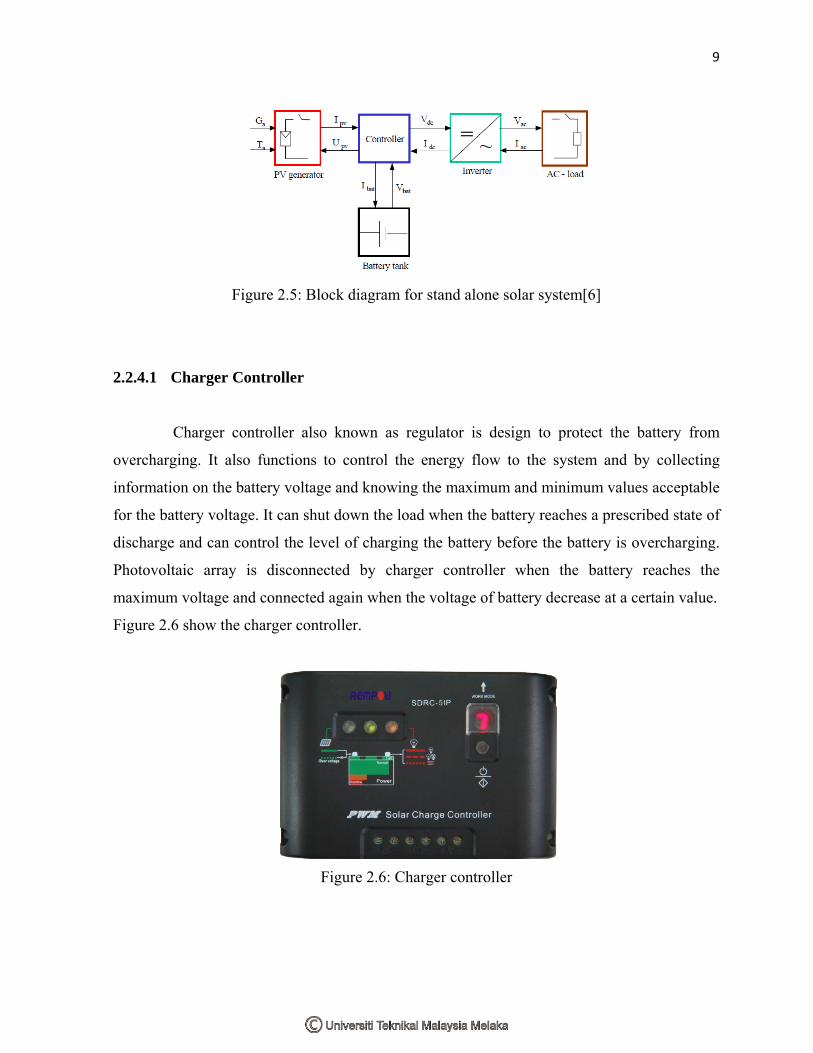
2.2.4.1 Charger Controller
Charger controller also known as regulator is design to protect the battery from
overcharging. It also functions to control the energy flow to the system and by collecting
information on the battery voltage and knowing the maximum and minimum values acceptable
for the battery voltage. It can shut down the load when the battery reaches a prescribed state of
discharge and can control the level of charging the battery before the battery is overcharging.
Photovoltaic array is disconnected by charger controller when the battery reaches the
maximum voltage and connected again when the voltage of battery decrease at a certain value.
Figure 2.6 show the charger controller.
Figure 2.6: Charger controller

10
2.2.4.2 Battery
Radiation from sun only can be used by solar panel to supply power during day. So,
storage must be added to the system. Battery is a storage device that can be used to store
energy from solar panel during daylight. During night, load that connected to the photovoltaic
system will get supply voltage from the battery that has been charged. Size of battery that is
use for photovoltaic system is depends on the demand voltage by the load that connected to
the photovoltaic system. Battery usually size in ampere hour (Ah) unit. For photovoltaic
system, the battery that is use is rechargeable battery. There are many type of rechargeable
battery such as nickel-cadmium, nickel-metal hydride, lead-acid and nickel-zinc that can be
used for photovoltaic system. However, the lead-acid battery is still most common use as
storage in photovoltaic system.
2.2.4.3 Inverter
Solar panel only generates direct current (DC) that only can be used by limited
number of load. When a photovoltaic system has an alternating current (AC) load, an inverter
must be included in the system to convert DC output to AC output. Most of residential devices
and appliances need AC as the supply. An inverter is a converter where the power flow is from
the DC to the AC side, namely having a DC voltage, as input, it produces a desired AC
voltage, as output. The process of convert DC to AC output is shown in Figure 2.7.
Figure 2.7: DC-AC convert process [6]

11
The function of the inverter is to keep on the AC side the voltage constant at the rated voltage
240V (single phase). Inverter also functions to convert the input power Pininto the output
power Pout with the best possible efficiency. The inverter’s efficiency is shown in Equation
(2.5)
𝜂𝜂 =𝑃𝑃𝑜𝑜𝑜𝑜𝑡𝑡𝑃𝑃𝑖𝑖𝑛𝑛
=𝐼𝐼𝑎𝑎𝑠𝑠𝑉𝑉𝑎𝑎𝑠𝑠 𝑠𝑠𝑜𝑜𝑠𝑠𝑐𝑐𝑉𝑉𝑑𝑑𝑠𝑠 𝐼𝐼𝑑𝑑𝑠𝑠
(2.5)
Where,
𝐼𝐼𝑑𝑑𝑠𝑠 : current required by the inverter from the DC side
𝑉𝑉𝑑𝑑𝑠𝑠 : input voltage for the inverter delivered by the DC side
2.2.5 Grid-connected Photovoltaic System
A grid-connected photovoltaic system is a photovoltaic system that connected to the
national grid network. It consist components likes solar panel, MPPT controller, inverter,
power conditioning and grid connected equipment. Grid connected photovoltaic system have
slightly different system compare to stand alone solar system. The inverter that converts from
DC to AC output is connected to the kWh meter. The kWh meter will measure the power
produce by the photovoltaic system. When the power produce is exceed the demand supply of
the user, the over power produce will be export to the grid but when power demand is high
than power produce by the photovoltaic system, national grid will supply the power to that
user. Figure 2.8 show grid-connected photovoltaic system and how it works.