a review of automotive thermoelectric generator · 2017-04-07 · exchanger uses ambient air as the...
TRANSCRIPT
International Research Journal of Engineering and Technology (IRJET) e-ISSN: 2395 -0056
Volume: 04 Issue: 03 | Mar -2017 www.irjet.net p-ISSN: 2395-0072
© 2017, IRJET | Impact Factor value: 5.181 | ISO 9001:2008 Certified Journal | Page 2787
A REVIEW OF AUTOMOTIVE THERMOELECTRIC GENERATOR
GOVIND MISHRA1, SHUSHIL KUMAR SHARMA 2
1B.E.scholar, D.MAT, Raipur, Chhattisgarh, India
2 Assistant professor, D.MAT, Raipur, Chhattisgarh, India
------------------------------------------------------------------------------------------------------------------Abstract- An automotive thermoelectric generator
(ATEG) is a device that converts some of the waste heat
of an internal combustion engine (IC) into electricity
using the Seebeck Effect. A typical ATEG consists of
four main elements: A hot-side heat exchanger, a cold-
side heat exchanger, thermoelectric materials, and a
compression assembly system. ATEGs can convert
waste heat from an engine's coolant or exhaust into
electricity. By reclaiming this otherwise lost energy,
ATEGs decrease fuel consumed by the electric
generator load on the engine. However, the cost of the
unit and the extra fuel consumed due to its weight
must be also considered.
Index Terms- Thermoelectric generator, Waste heat,
Internal combustion engine, See beck Effect,
Electricity, Fuel consumed.
1. INTRODUCTION 1.1 OVERVIEW
The main focus of energy conversion is on three
conversion locations mainly exhaust gas pipe (EGP),
exhaust gas recirculation (EGR) cooler, and retarder.
The most significant factors for the waste heat quality
are power density and temperature range.
The EGP is the target of the most automobile waste
heat recovery related research. The exhaust system
contains a large portion of the total waste heat in
vehicle. The gas flow in exhaust gas pipe is relatively
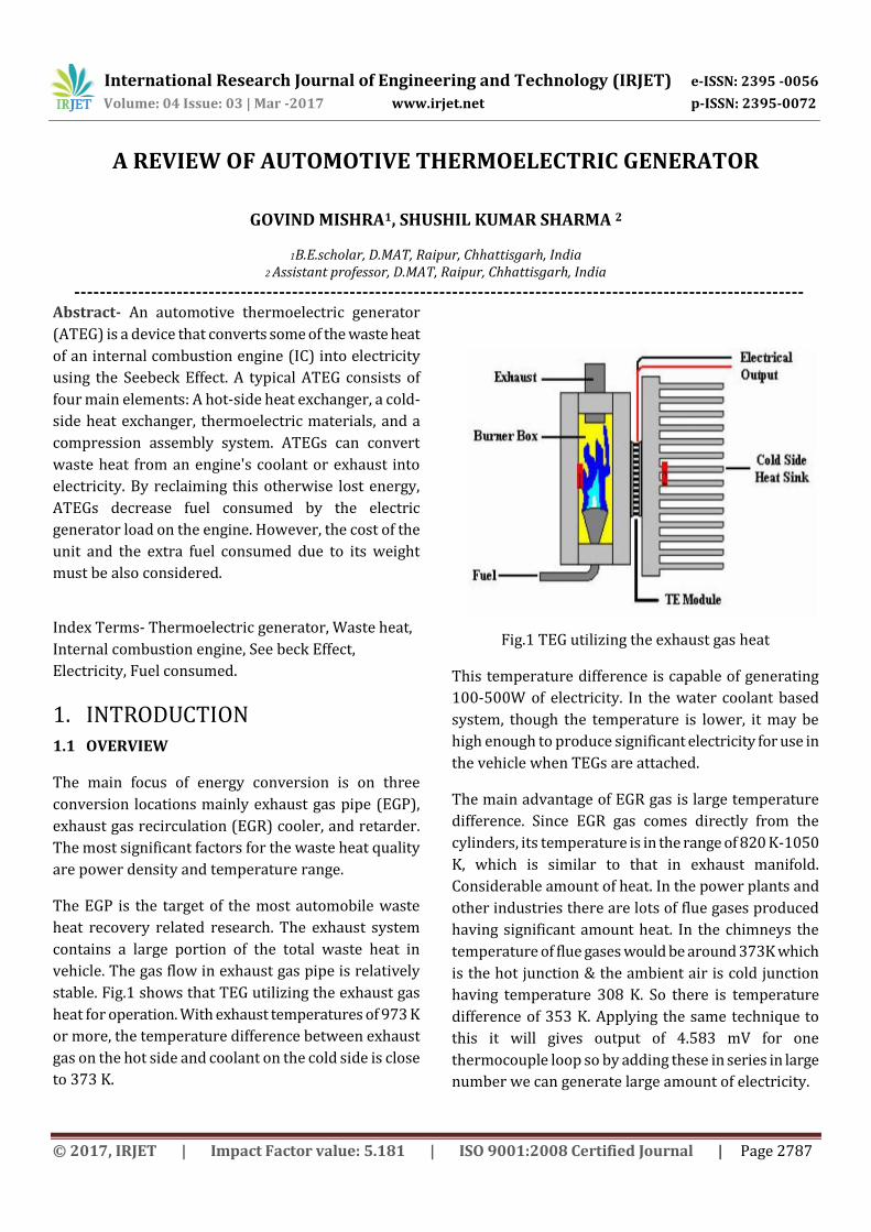
stable. Fig.1 shows that TEG utilizing the exhaust gas
heat for operation. With exhaust temperatures of 973 K
or more, the temperature difference between exhaust
gas on the hot side and coolant on the cold side is close
to 373 K.
Fig.1 TEG utilizing the exhaust gas heat
This temperature difference is capable of generating
100-500W of electricity. In the water coolant based
system, though the temperature is lower, it may be
high enough to produce significant electricity for use in
the vehicle when TEGs are attached.
The main advantage of EGR gas is large temperature
difference. Since EGR gas comes directly from the
cylinders, its temperature is in the range of 820 K-1050
K, which is similar to that in exhaust manifold.
Considerable amount of heat. In the power plants and
other industries there are lots of flue gases produced
having significant amount heat. In the chimneys the
temperature of flue gases would be around 373K which
is the hot junction & the ambient air is cold junction
having temperature 308 K. So there is temperature
difference of 353 K. Applying the same technique to
this it will gives output of 4.583 mV for one
thermocouple loop so by adding these in series in large
number we can generate large amount of electricity.
International Research Journal of Engineering and Technology (IRJET) e-ISSN: 2395 -0056
Volume: 04 Issue: 03 | Mar -2017 www.irjet.net p-ISSN: 2395-0072
© 2017, IRJET | Impact Factor value: 5.181 | ISO 9001:2008 Certified Journal | Page 2788
1.2 Case Study
1.2.1 GMC Sierra Pick-up Truck
In 2004, the Automobile Exhaust Thermoelectric
Generator (AETEG) project was launched by Clarkson
University and several companies, such as Delphi
Harrison Thermal System, GM Power train Division and
Hi-Z Technology, Inc. The purpose of the project is to
perform a feasibility investigation for the application of
thermoelectric generators on a GM pick-up truck, as
well as to develop a commercial plan for the designed
AETEG system. The device was targeting a power
output of 330W, being supplied with heat from the
exhaust and cooled
by the conventional coolant circuit. A CAD model of the
device can be seen in Fig.2. Efficiencies of the electronic
device converting the electrically generated TEG in the
order of 80-90%. The maximum amount of electricity
created was 140 W to 225 W, with different types of
configurations.
Fig.2 The CAD model of the assembled AETEG in GM
pick-up truck project.
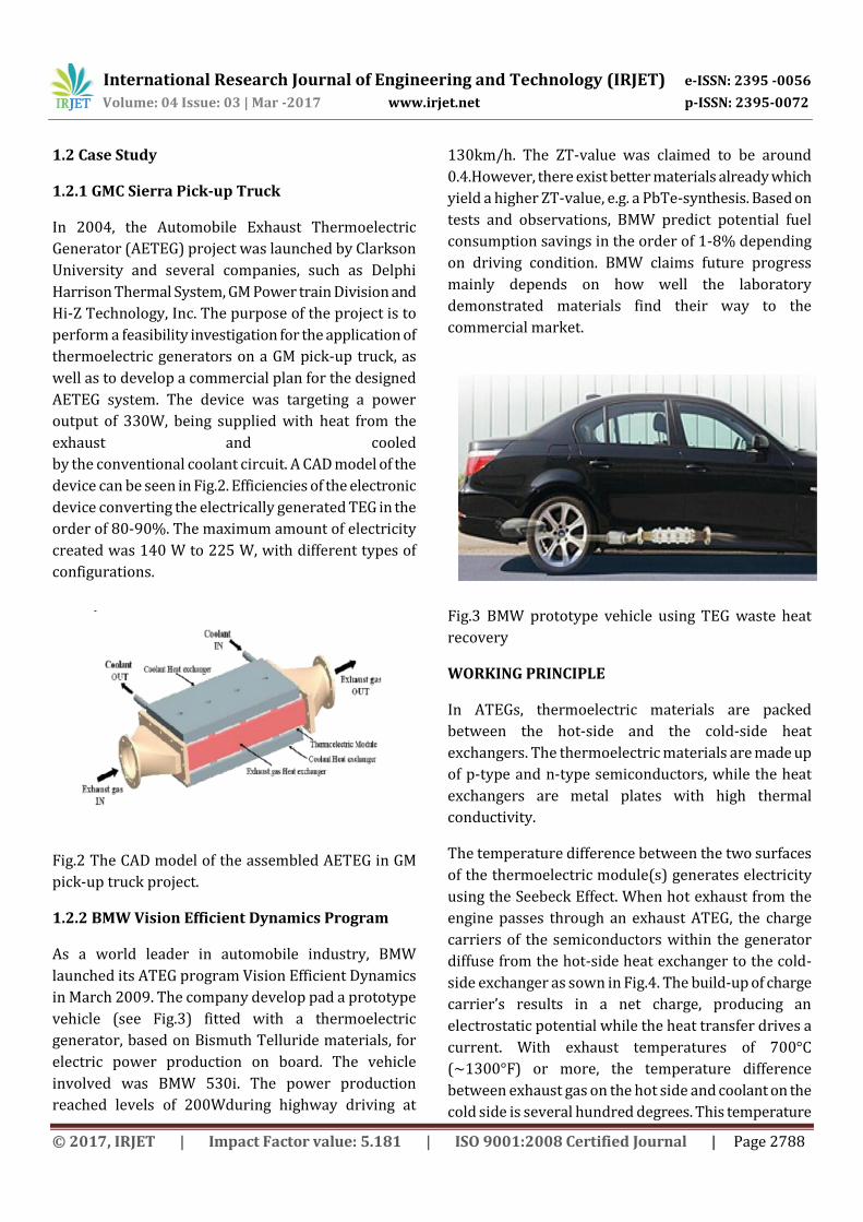
1.2.2 BMW Vision Efficient Dynamics Program
As a world leader in automobile industry, BMW
launched its ATEG program Vision Efficient Dynamics
in March 2009. The company develop pad a prototype
vehicle (see Fig.3) fitted with a thermoelectric
generator, based on Bismuth Telluride materials, for
electric power production on board. The vehicle
involved was BMW 530i. The power production
reached levels of 200Wduring highway driving at
130km/h. The ZT-value was claimed to be around
0.4.However, there exist better materials already which
yield a higher ZT-value, e.g. a PbTe-synthesis. Based on
tests and observations, BMW predict potential fuel
consumption savings in the order of 1-8% depending
on driving condition. BMW claims future progress
mainly depends on how well the laboratory
demonstrated materials find their way to the
commercial market.
Fig.3 BMW prototype vehicle using TEG waste heat
recovery
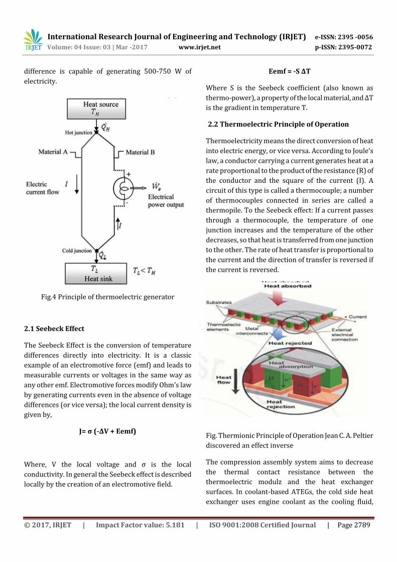
WORKING PRINCIPLE
In ATEGs, thermoelectric materials are packed
between the hot-side and the cold-side heat
exchangers. The thermoelectric materials are made up
of p-type and n-type semiconductors, while the heat
exchangers are metal plates with high thermal
conductivity.
The temperature difference between the two surfaces
of the thermoelectric module(s) generates electricity
using the Seebeck Effect. When hot exhaust from the
engine passes through an exhaust ATEG, the charge
carriers of the semiconductors within the generator
diffuse from the hot-side heat exchanger to the cold-
side exchanger as sown in Fig.4. The build-up of charge
carrier’s results in a net charge, producing an
electrostatic potential while the heat transfer drives a
current. With exhaust temperatures of 700°C
(~1300°F) or more, the temperature difference
between exhaust gas on the hot side and coolant on the
cold side is several hundred degrees. This temperature
International Research Journal of Engineering and Technology (IRJET) e-ISSN: 2395 -0056
Volume: 04 Issue: 03 | Mar -2017 www.irjet.net p-ISSN: 2395-0072
© 2017, IRJET | Impact Factor value: 5.181 | ISO 9001:2008 Certified Journal | Page 2789
difference is capable of generating 500-750 W of
electricity.
Fig.4 Principle of thermoelectric generator
2.1 Seebeck Effect
The Seebeck Effect is the conversion of temperature
differences directly into electricity. It is a classic
example of an electromotive force (emf) and leads to
measurable currents or voltages in the same way as
any other emf. Electromotive forces modify Ohm’s law
by generating currents even in the absence of voltage
differences (or vice versa); the local current density is
given by,
J= σ (-ΔV + Eemf)
Where, V the local voltage and ς is the local
conductivity. In general the Seebeck effect is described
locally by the creation of an electromotive field.
Eemf = -S ΔT
Where S is the Seebeck coefficient (also known as
thermo-power), a property of the local material, and ΔT
is the gradient in temperature T.
2.2 Thermoelectric Principle of Operation
Thermoelectricity means the direct conversion of heat
into electric energy, or vice versa. According to Joule's
law, a conductor carrying a current generates heat at a
rate proportional to the product of the resistance (R) of
the conductor and the square of the current (I). A
circuit of this type is called a thermocouple; a number
of thermocouples connected in series are called a
thermopile. To the Seebeck effect: If a current passes
through a thermocouple, the temperature of one
junction increases and the temperature of the other
decreases, so that heat is transferred from one junction
to the other. The rate of heat transfer is proportional to
the current and the direction of transfer is reversed if
the current is reversed.
Fig. Thermionic Principle of Operation Jean C. A. Peltier
discovered an effect inverse
The compression assembly system aims to decrease
the thermal contact resistance between the
thermoelectric modulz and the heat exchanger
surfaces. In coolant-based ATEGs, the cold side heat
exchanger uses engine coolant as the cooling fluid,
International Research Journal of Engineering and Technology (IRJET) e-ISSN: 2395 -0056
Volume: 04 Issue: 03 | Mar -2017 www.irjet.net p-ISSN: 2395-0072
© 2017, IRJET | Impact Factor value: 5.181 | ISO 9001:2008 Certified Journal | Page 2790
while in exhaust-based ATEGs, the cold-side heat
exchanger uses ambient air as the cooling fluid.
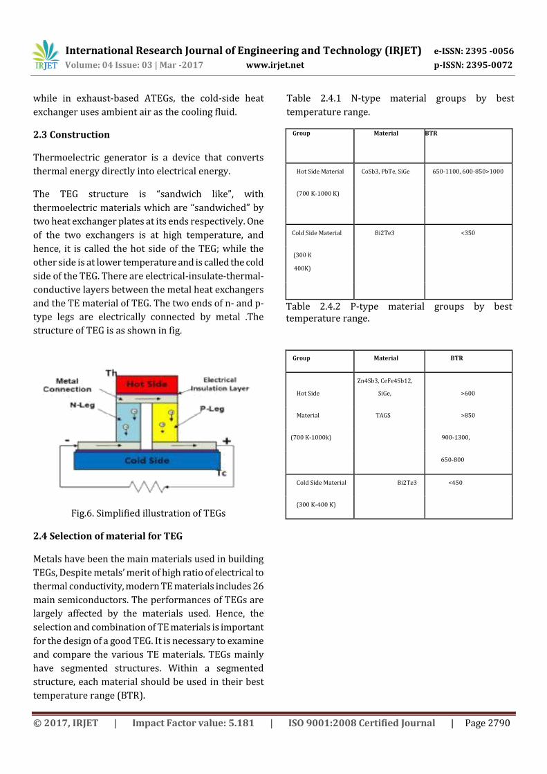
2.3 Construction
Thermoelectric generator is a device that converts
thermal energy directly into electrical energy.
The TEG structure is “sandwich like”, with
thermoelectric materials which are “sandwiched” by
two heat exchanger plates at its ends respectively. One
of the two exchangers is at high temperature, and
hence, it is called the hot side of the TEG; while the
other side is at lower temperature and is called the cold
side of the TEG. There are electrical-insulate-thermal-
conductive layers between the metal heat exchangers
and the TE material of TEG. The two ends of n- and p-
type legs are electrically connected by metal .The
structure of TEG is as shown in fig.
Fig.6. Simplified illustration of TEGs
2.4 Selection of material for TEG
Metals have been the main materials used in building
TEGs, Despite metals’ merit of high ratio of electrical to
thermal conductivity, modern TE materials includes 26
main semiconductors. The performances of TEGs are
largely affected by the materials used. Hence, the
selection and combination of TE materials is important
for the design of a good TEG. It is necessary to examine
and compare the various TE materials. TEGs mainly
have segmented structures. Within a segmented
structure, each material should be used in their best
temperature range (BTR).
Table 2.4.1 N-type material groups by best
temperature range.
Group Material BTR
Hot Side Material CoSb3, PbTe, SiGe 650-1100, 600-850>1000
(700 K-1000 K)
Cold Side Material Bi2Te3 <350
(300 K
400K)
Table 2.4.2 P-type material groups by best temperature range.
Group Material BTR
Hot Side
Zn4Sb3, CeFe4Sb12,
SiGe, >600
Material TAGS >850
(700 K-1000k) 900-1300,
650-800
Cold Side Material Bi2Te3 <450
(300 K-400 K)
International Research Journal of Engineering and Technology (IRJET) e-ISSN: 2395 -0056
Volume: 04 Issue: 03 | Mar -2017 www.irjet.net p-ISSN: 2395-0072
© 2017, IRJET | Impact Factor value: 5.181 | ISO 9001:2008 Certified Journal | Page 2791
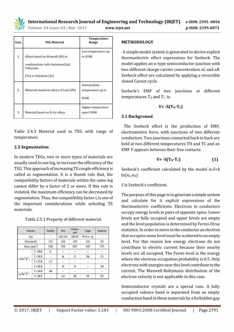
Table 2.4.3 Material used in TEG with range of
temperature.
2.5 Segmentation
In modern TEGs, two or more types of materials are
usually used in one leg, to increase the efficiency of the
TEG. This approach of increasing TE couple efficiency is
called as segmentation. It is a thumb rule that, the
compatibility factors of materials within the same leg
cannot differ by a factor of 2 or more. If this rule is
violated, the maximum efficiency can be decreased by
segmentation. Thus, the compatibility factor s, is one of
the important considerations while selecting TE
materials.
Table 2.5.1 Property of different material.
METHODOLOGY
A simple model system is generated to derive explicit
thermoelectric effect expressions for Seebeck. The
model applies an n-type semiconductor junction with
two different charge-carrier concentration nL and nR.
Seebeck effect are calculated by applying a reversible
closed Carnot cycle.
Seebeck's EMF of two junctions at different
temperatures TH and TC is:
V= -S(TH-TC)
3.1 Background.
The Seebeck effect is the production of EMF,
electromotive force, with junctions of two different
conductors. Two junctions connected back to back are
held at two different temperatures TH and TC and an
EMF V appears between their free contacts:
V= -S(TH-TC) (1)
Seebeck's coefficient calculated by the model is:𝑆=𝑘
ln(𝑛𝐿/𝑛𝑅)
S is Seebeck's coefficient.
The purpose of this page is to generate a simple system
and calculate for it explicit expressions of the
thermoelectric coefficients. Electrons in conductors
occupy energy levels in pairs of opposite spins. Lower
levels are fully occupied and upper levels are empty
and the level population is determined by Fermi-Dirac
statistics. In order to move in the conductor an electron
that occupies some level must be scattered to an empty
level. For this reason low energy electrons do not
contribute to electric current because their nearby
levels are all occupied. The Fermi level is the energy
where the electron occupation probability is 0.5. Only
electrons with energies near this level contribute to the
current. The Maxwell-Boltzmann distribution of the
electron velocity is not applicable in this case.
Semiconductor crystals are a special case. A fully
occupied valence band is separated from an empty
conduction band in these materials by a forbidden gap
S.no. TEG Material Temperature Range
1. Alloys based on Bismuth (Bi) in
Low temperature up
to 450K
combinations with Antimony(An), Tellurium
(Te) or Selenium (Se)
2. Materials based on alloys of Lead (Pb)
Intermediate
temperature up to
850K
3. Material based on Si-Ge alloys
Higher temperature
upto1300K
International Research Journal of Engineering and Technology (IRJET) e-ISSN: 2395 -0056
Volume: 04 Issue: 03 | Mar -2017 www.irjet.net p-ISSN: 2395-0072
© 2017, IRJET | Impact Factor value: 5.181 | ISO 9001:2008 Certified Journal | Page 2792
without energy levels in it. If the gap is large enough
direct thermal excitation of electrons from band to
band is negligible and the material will be an insulator.
Introduction of donors to the material will add
electrons to the conduction band and make it n-type.
Acceptors will add holes to the valence band and make
it p-type. A donor atom has an extra electron,
compared to a crystal atom, at a level just below the
bottom of the conduction band and it will be thermally
transferred to the conduction band where it is free to
move. An acceptor atom has one less electron just
above the valence band. An Electron caught by the
acceptor will leave a free moving hole in the valence
band. Practically, if the donor level is shallow, then all
the donors will be ionized in n-type material. So that
the density of free moving electrons is equal to the
donor density. Similarly, the density of free moving
holes is equal to the acceptor density in p-type
material.
If the doping levels are not too high the charge carrier
density, either of electrons or holes, will be lower than
the energy level density within the bands. Each carrier
may be scattered to many neighboring empty levels so
that practically it is a free particle. The Maxwell-
Boltzmann velocity distribution will then be applicable
to the carriers.
3.2 Thermal Energy of a Particle
The average kinetic energy is calculated by summing
all the squared velocities over all directions in space in
a spatial angle of 4π determined by a declination angle
θ, 0 to π and
azimuth angle of 2π. Each velocity is weighed by a
distribution probability f0(x, v, θ):
<𝑣2>=∫𝑓0(𝑥,𝑣,𝜃) ׀𝒗2׀𝑑3𝒗, ( 2)
where v = |v| and 𝑑3𝒗=2𝜋𝑣2𝑑𝑣𝑆𝑖𝑛(𝜃)𝑑𝜃.
Maxwell-Boltzmann distribution is:
𝑓0(𝑣)=(𝑚/2𝜋𝑘𝑇)(3/2)𝑒−𝑚𝑣2/2𝑘𝑇,
(3)
where the pre-exponential factor in (3), determined
by the condition
πv2𝑓0𝑑𝑣=1, is applied to the calculation of <v2>. By
transforming to a dimensionless variable
𝑥=(𝑚/2𝑘𝑇)1/2𝑣, and using the integrals in appendix A :
<𝑣2>=4𝜋∫𝑓0(𝑣)𝑣4𝑑𝑣=3𝑘𝑇/𝑚. (4)
The average kinetic energy is:
𝑚<𝑣2>/2=(3/2)𝑇. (5)
3.3 Contact Potential
Consider two pieces of n-type semiconductor with
higher nL and lower nR electron densities, where nL
and nR are equal to the corresponding donor densities.
Therefore, these densities are temperature
independent. If the two pieces are brought into contact
to form a junction, electrons will start to diffuse from
the left higher nL to the right lower nR density. The
diffusion generates a space charge region, electric field,
and potential difference Vc between the two pieces,
that stops further electron diffusion. Vc is the contact
potential. It is not directly measureable by a voltmeter,
for example, because the voltmeter probes make their
own contact potentials with the two ends of the
junction. The sum of all the junction potentials is then
zero.
If the two pieces are separated after being in contact,
their capacity will drop, the voltage between them will
go up and it will then be measureable. Methods that
measure the contact potential are based on this
phenomenon is calculated:
𝑒−𝑒𝑉𝑐/𝑘𝑇=𝑛𝑅/𝑛𝐿, (6)
or (16):
𝑉𝑐=(𝑘𝑇/𝑒)ln(𝑛𝐿/𝑛𝑅). (7)
e is the electron charge and k is Boltzmann's
constant.
It is assumed that the junction is perpendicular to the
x-direction, and that the depth of the space charge layer
in it is small compared to the electron's mean free path.
International Research Journal of Engineering and Technology (IRJET) e-ISSN: 2395 -0056
Volume: 04 Issue: 03 | Mar -2017 www.irjet.net p-ISSN: 2395-0072
© 2017, IRJET | Impact Factor value: 5.181 | ISO 9001:2008 Certified Journal | Page 2793
The thermal velocity of electrons on the left side must
have a minimal component vx in order to overcome the
potential barrier and cross to the right side: (1/2) 2> .
Electrons on the right side do not have a barrier for
crossing back to the left. An electron that crosses the
junction from left to right, will be slowed by the electric
field and lose energy eVc. This energy will be thermally
regained from its vicinity. An electron moving in the
opposite direction will be accelerated by the field and
thermally deliver the field-gained energy to its vicinity.
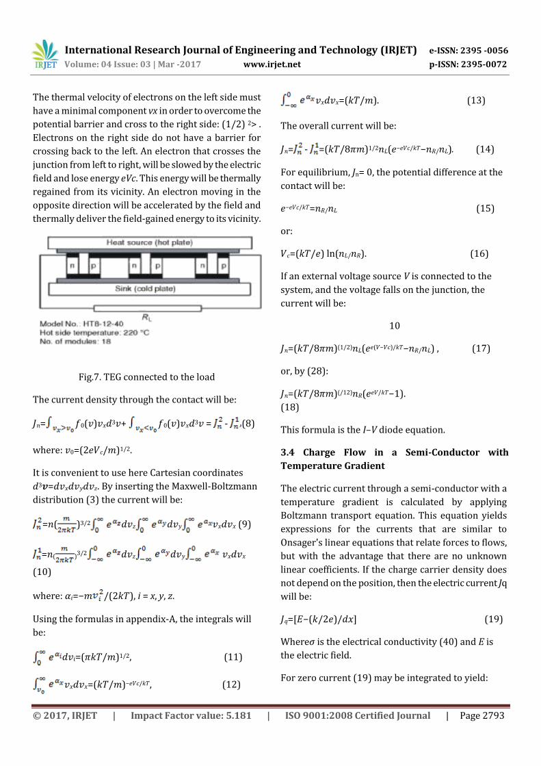
Fig.7. TEG connected to the load
The current density through the contact will be:
𝐽𝑛= 𝑓0(𝑣)𝑣𝑥𝑑3𝑣+ 𝑓0(𝑣)𝑣𝑥𝑑3𝑣 = - (8)
where: 𝑣0=(2𝑒𝑉𝑐/𝑚)1/2.
It is convenient to use here Cartesian coordinates
𝑑3𝒗=𝑑𝑣𝑥𝑑𝑣𝑦𝑑𝑣𝑧. By inserting the Maxwell-Boltzmann
distribution (3) the current will be:
=𝑛( )3/2 𝑑𝑣𝑧 𝑑𝑣𝑦 𝑣𝑥𝑑𝑣𝑥 (9)
=𝑛( )3/2 𝑑𝑣𝑧 𝑑𝑣𝑦 𝑣𝑥𝑑𝑣𝑥
(10)
where: 𝛼𝑖=−𝑚 /(2𝑘𝑇), i = x, y, z.
Using the formulas in appendix-A, the integrals will
be:
𝑑𝑣𝑖=(𝜋𝑘𝑇/𝑚)1/2, (11)
𝑣𝑥𝑑𝑣𝑥=(𝑘𝑇/𝑚)−𝑒𝑉𝑐/𝑘𝑇, (12)
𝑣𝑥𝑑𝑣𝑥=(𝑘𝑇/𝑚). (13)
The overall current will be:
𝐽𝑛= - =(𝑘𝑇/8𝜋𝑚)1/2𝑛𝐿(𝑒−𝑒𝑉𝑐/𝑘𝑇−𝑛𝑅/𝑛𝐿). (14)
For equilibrium, Jn= 0, the potential difference at the
contact will be:
𝑒−𝑒𝑉𝑐/𝑘𝑇=𝑛𝑅/𝑛𝐿 (15)
or:
𝑉𝑐=(𝑘𝑇/𝑒) ln(𝑛𝐿/𝑛𝑅). (16)
If an external voltage source V is connected to the
system, and the voltage falls on the junction, the
current will be:
10
𝐽𝑛=(𝑘𝑇/8𝜋𝑚)(1/2)𝑛𝐿(𝑒𝑒(𝑉−𝑉𝑐)/𝑘𝑇−𝑛𝑅/𝑛𝐿) , (17)
or, by (28):
𝐽𝑛=(𝑘𝑇/8𝜋𝑚)(/12)𝑛𝑅(𝑒𝑒𝑉/𝑘𝑇−1).
(18)
This formula is the I–V diode equation.
3.4 Charge Flow in a Semi-Conductor with
Temperature Gradient
The electric current through a semi-conductor with a
temperature gradient is calculated by applying
Boltzmann transport equation. This equation yields
expressions for the currents that are similar to
Onsager's linear equations that relate forces to flows,
but with the advantage that there are no unknown
linear coefficients. If the charge carrier density does
not depend on the position, then the electric current Jq
will be:
𝐽𝑞=[𝐸−(𝑘/2𝑒)/𝑑𝑥] (19)
Whereσ is the electrical conductivity (40) and E is
the electric field.
For zero current (19) may be integrated to yield:
International Research Journal of Engineering and Technology (IRJET) e-ISSN: 2395 -0056
Volume: 04 Issue: 03 | Mar -2017 www.irjet.net p-ISSN: 2395-0072
© 2017, IRJET | Impact Factor value: 5.181 | ISO 9001:2008 Certified Journal | Page 2794
𝑉=(𝑘/2𝑒)ΔT. (20)
By using the values of k and e a voltage gradient of 43
microvolt/degree, independent of the charge density,
is developed between the cold and hot ends of the
conductor.
The charge flow within a conductor is calculated by
application of Boltzmann transport equation. A
temperature gradient along the x-coordinate is
assumed.
( x,y ) is a non-equilibrium distribution function that
determines the probability of a particle within a
system to be at some place x and to have some local
thermal velocity v. The Boltzmann transport equation
expresses this global non-equilibrium distribution in
terms of local equilibrium distributions f0(x ,y ). The
equation enables application of properties of
equilibrium systems to the study of a non-equilibrium
system. The linear transport equation is:
𝑓(𝑥,𝑣,𝜃)=𝑓0(𝑥,𝑣)−𝑙𝐶𝑜𝑠(𝜃)[(𝜕𝑓0/𝜕𝑥)+(𝒂/𝑣)(𝜕𝑓0/𝜕𝑣)] ,
(21)
Where l is the mean free path, v is the velocity vector, v
= |v|, and θ is the vector direction relative to the x-
coordinate. a is the acceleration due to external force.
For example, a = e E / m, where E is the electric field, e
is the particle charge and m is its mass. Equation (21) is
obtained from the classical linear transport equation
[20] by replacing the relaxation time τ = l / v.
The currents: A particle moving with a velocity v will
cross a plane section of the conductor at x during a
time Δt if its distance from the plane is less than ( ) .
The particle current through a unit cross section at x is
obtained by summing all the velocities in all directions
(spatial angle of 4π). Each velocity weighed by the
distribution probability:
𝐽𝑛=∫(𝑥)𝑓(𝑥,𝑣,𝜃)𝑣𝐶𝑜𝑠(𝜃)𝑑3𝑣 , (22)
where 𝑑3𝑣=2𝜋𝑣2𝑑𝑣𝑆𝑖𝑛(𝜃)𝑑𝜃. Substitution of the
distribution function (21) into (22) yields the current:
𝐽𝑛=−(4𝜋𝑙/3)[(𝑒𝐸/𝑚)∫𝑛(𝑥)(𝜕𝑓0/𝜕𝑣)𝑣2𝑑𝑣+∫𝑛(𝑥)(𝜕𝑓0
/𝜕𝑥)𝑣3𝑑𝑣],(23)
where the f0 contribution in (23) is zero, and the
trigonometric integral is ∫𝐶𝑜𝑠(𝜃) 𝑆𝑖𝑛(𝜃)𝑑𝜃=2/3.
Since the energy associated with each particle is
(1/2)𝑣2 the energy current will be, by a similar
calculation:
𝐽𝑢=(4𝜋𝑙/3)[(𝑒𝐸/𝑚)∫𝑛(𝑥)(𝜕𝑓0/𝜕𝑣)𝑣4𝑑𝑣+∫𝑛(𝑥)(𝜕𝑓0/𝜕𝑥)𝑣5𝑑𝑣]. (24)
The currents will now be calculated by applying the
Maxwell-Boltzmann distribution (3). Since (by (3)),
𝜕𝑓0/𝜕𝑣=−(𝑚𝑣/𝑘𝑇)𝑓0, the particle current will be:
𝐽𝑛=−(4𝜋𝑙/3)[(𝑒𝐸/𝑘𝑇)−(𝑑/𝑑𝑥)][𝑛(𝑥)∫(𝑓0)𝑣3𝑑𝑣)]. (25)
Or, by transforming to a dimensionless variable
𝑥=(𝑚/2𝑘𝑇)1/2𝑣, and using the integrals in appendix A:
𝐽𝑛=[4𝑙/3(2𝜋𝑚)1/2][𝑒𝐸𝑛/(𝑘𝑇)1/2−𝑑(𝑛(𝑘𝑇)1/2)/𝑑𝑥]. (26)
Assuming that the charge density does not depend on
the position, the current will be:
𝐽𝑛=[(4𝑙/3)/(2𝜋𝑚)1/2](1/𝑘𝑇)1/2𝑛[𝑒𝐸−(1/2)𝑑(𝑘𝑇)/𝑑𝑥].
(27)
The charge current will be 𝐽𝑞=𝑒𝐽𝑛. A similar calculation
yields the energy current:
𝐽𝑢=2[(4𝑙/3)/(2𝜋𝑚)1/2][(𝑘𝑇)1/2𝑒𝐸𝑛−𝑑(𝑛𝑘𝑇)3/2 /𝑑𝑥], (28)
or, by combining (26) and (28):
𝐽𝑢=2𝑘𝑇𝐽𝑛−2[(4𝑙/3)/(2𝜋𝑚)1/2]𝑛𝑘𝑇½𝑑(𝑘𝑇)/𝑑𝑥. (29)
Equation (29) expresses the energy current as a sum of
two terms. The first is convection, the energy
associated with the particle flow, and the second is heat
conduction, which is proportional to the temperature
gradient and independent of the particle current.
Equations (26), (29) may be applied to calculate the
diffusivity, electrical and thermal conductivity, and to
verify the Wiedemann-Franz law and Einstein
relations.
For example, the electrical conductivity σ, defined by
𝐽𝑞=𝑒𝐽(𝑑𝑛/𝑑𝑥=0,𝑑𝑇/𝑑𝑥=0)=𝜎𝐸, is:
International Research Journal of Engineering and Technology (IRJET) e-ISSN: 2395 -0056
Volume: 04 Issue: 03 | Mar -2017 www.irjet.net p-ISSN: 2395-0072
© 2017, IRJET | Impact Factor value: 5.181 | ISO 9001:2008 Certified Journal | Page 2795
𝜎=[(4𝑙/3)/(2𝜋𝑚)1/2]𝑒2𝑛/(𝑘𝑇)1/2. (30)
Equations (26), (28) are similar to Onsager's linear
equations that relate forces to flows, but have the
advantage that they do not include unknown linear
coefficients like Onsager's. The values of these
coefficients may be obtained by comparing the two sets
of equations.
Appendix A: Integrals
𝑒-𝑎2𝑥2𝑑𝑥=(𝑛+1/2)/2𝑎𝑛+1. (31)
Γ is the gamma function: (𝑛)=(𝑛−1)! (32)
(𝑥+1)=𝑥𝛤(𝑥) (33)
(𝑥)𝛤(𝑥+1/2)=𝛤(2𝑥)𝜋1/2/22𝑥−1 (34)
(1/2)=𝜋1/2 (35)
(3/2)=(1/2)𝜋1/2 (36)
(5/2)=(3/4)𝜋1/2(37)
3.5 Thermoelectric Effects
Direct conversion of thermal to electrical energy is
analysed by applying the original Carnot method to a
junction device operating in a reversible four step
closed cycle. The "Carnot machine" Two junctions of
semiconductors are connected in parallel. The two
semiconductors are in permanent contact in the left
junction and are separated and moveable in the right
junction. The distance between the separated pieces is
externally controlled. The connecting wires are made
of the same semiconductor material so that there is
only one contact junction in the device.
The contact potential Vc within a junction is given by
(7). Since the right junction parts are electrically
charged, there will be attraction force between them.
Changing the distance between them requires
mechanical work. The machine operates in a four step
cycle between a hotter heat-bath TH and a colder heat-
bath TC.
In step-1 the machine is attached to the hot bath TH.
The right upper part moves down isothermally toward
the lower part with a constant junction potential VH.
The increasing capacity of the right junction drives
charge ΔQH that flows from the left contact junction
that absorbs heat = from the hot bath (Peltier effect).
The pieces of the right junction perform equivalent
work on the external force that hold them in place.
In step-2 the machine is separated from the hot bath
TH and the right upper part moves adiabatically
further down toward the lower part. The machine
cools down until the temperature drops to TC of the
cold bath. The junction potential drops from VH to VC.
In step-3 the machine is attached to the cold bath TC.
The upper part moves back isothermally with constant
VC and recedes from the lower part. The decreasing
capacity of the right junction drives charge ΔQC that
flows in the opposite direction to step-1. The flow
through the left junction delivers heat = to the cold
bath (Peltier effect reversed direction) and the external
force performs an equivalent work on the right
junction.
In step-4 the machine is separated from the cold bath
TC. The upper part continues to move up adiabatically
and the machine heats up until it reaches the
temperature TH of the hot bath. The junction potential
goes up from VC to VH, its original state, and a full cycle
is completed.
The adiabatic work done by the machine on the
external force in step-2 is equal to the adiabatic work
done by the external force on the machine in step-4.
The EMF V of the machine is the work done by moving
a unit charge in a complete closed cycle. This work is
equal to the sum of step-1 and step-3 for a unit charge
e. using (7) the work will be:
3.6 Efficiency
Currently, ATEGs are about 5% efficient. However,
advancements in thin-film and quantum well
technologies could increase efficiency up to 15% in the
future.
International Research Journal of Engineering and Technology (IRJET) e-ISSN: 2395 -0056
Volume: 04 Issue: 03 | Mar -2017 www.irjet.net p-ISSN: 2395-0072
© 2017, IRJET | Impact Factor value: 5.181 | ISO 9001:2008 Certified Journal | Page 2796
The efficiency of an ATEG is governed by the
thermoelectric conversion efficiency of the materials
and the thermal efficiency of the two heat exchangers.
The ATEG efficiency can be expressed as:
ζOV = ζCONV х ζHX х ρ
Where:
ζOV : The overall efficiency of the ATEG
ζCONV : Conversion efficiency of thermoelectric materials
ζHX: Efficiency of the heat exchangers
ρ : The ratio between the heat passed through thermoelectric materials to that passed from the hot side to the cold side. EFFECT AND IMPACT ON SOCIOECONOMICAL
DEVELOPMENT
The primary goal of ATEGs is to reduce fuel
consumption. Forty percent of an IC engine’s energy is
lost through exhaust gas heat. By converting the lost
heat into electricity, ATEGs decrease fuel consumption
by reducing the electric generator load on the engine.
ATEGs allow the automobile to generate electricity
from the engine's thermal energy rather than using
mechanical energy to power an electric generator.
Since the electricity is generated from waste heat that
would otherwise be released into the environment, the
engine burns less fuel to power the vehicle's electrical
components, such as the headlights. Therefore, the
automobile releases fewer emissions.
Decreased fuel consumption also results in increased
fuel economy. Replacing the conventional electric
generator with ATEGs could ultimately increase the
fuel economy by up to 4%.
The ATEG’s ability to generate electricity without
moving parts is an advantage over mechanical electric
generators alternatives.
Advantages of Thermoelectric power generators
over other technologies.
APPLICATION
As discussed in section 1 TEGs are used to develop
electricity from waste heat released from EGP due to
combustion of fuel and from power plants and some
industries due to flue gases from chimneys.
Other applications of TEGs
Camping, portable coolers, cooling electronic
components and small instruments. A camping/car
type electric cooler can typically reduce the
temperature by up to 20 °C (36 °F) below the ambient
temperature. The cooling effect of Peltier heat pumps
can also be used to extract water from the air in
dehumidifiers. Climate-controlled jackets, wine
coolers, thermal cyclers, satellites and spacecraft. Used
for the synthesis of DNA by polymerase chain reaction
(PCR).
CONCLUSION
Waste heat recovery entails capturing and reusing the
waste heat from internal combustion engine and using
it for heating or generating mechanical or electrical
work. It would also help to recognize the improvement
in performance and emissions of the engine if these
technologies were adopted by the automotive
manufacturers.
By using this thermoelectric system one can generate
electricity from the high temperature difference and it
is available at low cost. In heavy duty vehicles the
smoke coming out of the exhaustion system will form
the NOx gases which are major concern for the
greenhouse gases. But because of this the temperature
will come down of exhaust gases so, the formation of
the NOx gases will be minimal.
If this concept of thermoelectric system is taken to the
Nano level or micro level then there will be ample
amount of electricity can be generated which are just
wasted into the atmosphere.
International Research Journal of Engineering and Technology (IRJET) e-ISSN: 2395 -0056
Volume: 04 Issue: 03 | Mar -2017 www.irjet.net p-ISSN: 2395-0072
© 2017, IRJET | Impact Factor value: 5.181 | ISO 9001:2008 Certified Journal | Page 2797
11.REFERENCES
1. Yang, Jihui. “Automotive Applications of Thermoelectric Materials”. Journal ofElectronic Materials, 2009, VOL 38; page 1245
2. Snyder, G. J. Toberer, E. S. “Complex Thermoelectric Materials”. Nature materials, 2008 , VOL 7; NUMBER 2, pages 105-114
3. “TEGs - Using Car Exhaust To Lower Emissions”. Scientific Blogging. June 3, 2008
4. Laird, Lorelei. “Could TEG improve your car's efficiency?”. DOE Energy Blog. August16, 2010
5. http://purl.access.gpo.gov/GPO/LPS118101 6. Ikoma, K., M.Munekiyo, K.Furuya, M.Kobayashi,
T.Izumi, and K.Shinohara (1998). Thermoelectric Module and Generator for Gasoline Engine Vehicle. Proc. 17th International Conference on Thermoelectrics. Nagoya, Japan: IEEE pp. 464-467.
7. Yu, C. “Thermoelectric automotive waste heat energy recovery using maximum power point tracking”. Energy Conversion and Management, 2008, VOL 50; page 1506
8. Stabler, Francis. "Automotive Thermoelectric Generator Design Issues". DOE Thermoelectric Applications Workshop.
9. Stabler, Francis. "Benefits of Thermoelectric Technology for the Automobile". DOE Thermoelectric Applications Workshop.o B. Neild, Jr., SAE-645A (1963).
10. Birkholz, U., et al. "Conversion of Waste Exhaust Heat in Automobile using FeSi2 Thermoelements". Proc. 7th International Conference on Thermoelectric Energy Conversion. 1988, Arlington, USA, pp. 124-128.
11. Thacher E. F., Helenbrook B. T., Karri M. A., and Richter Clayton J. "Testing an automobile thermoelectric exhaust based thermoelectric generator in a light truck" Proceedings of the I MECH E Part D Journal of Automobile Engineering, Volume 221, Number 1, 2007, pp. 95-107(13)
12. Kushch A., Karri M. A., Helenbrook B. T. and Richter Clayton J., "The Effects of an Exhaust Thermoelectric Generator of a GM Sierra Pickup Truck." Proceedings of Diesel Engine Emission Reduction (DEER) conference, 2004, Coronado, California,USA
13. LaGrandeur J., Crane D., Eder A., "Vehicle Fuel Economy Improvement through Thermoelectric Waste Heat Recovery", DEER Conference, 2005, Chicago, IL, USA
14. “2012 10Best: 10 Most Promising Future Technologies: Thermal Juice”, Car & Driver, December 201Jaydeep. V. Joshi1 and N. M. Patel (2012), Thermoelectric system to generate electricity from waste heat of the flue gases, Advances in Applied Science Research, 3 (2):1077-1084
15 Basel I. Ismail, Wael H. Ahmed (2009), Thermoelectric Power Generation Using Waste heat as an Alternative Green Technology, Recent Patents on Electrical Engineering, 2, 27-39 16 Adavbiele A.S. (2013), Generation of Electricity
from Gasoline Engine Waste Heat, Journal of Energy Technologies and Policy, Vol.3, No.5,
17 Peltier application notes 20050 SW 112th Ave. Tualatin, Oregon 97062
18 KTH Information and Communication Technology, Thermoelectric-Generator-Based DCDC Conversion Network for Automotive Applications. Master of Science Thesis Stockholm, Sweden 2011.Trita-ICT-EX-2011:58.Molanli
19 Ravikumar, N., Ramakrishna, K., Sitaramaraju, A. V., Thermodynamic Analysis of Heat Recovery Steam Generator in Combined Cycle Power Plant, Thermal Science, 11 (2007), 4, pp. 143-156.
20 Polyzakis, A. L., et al., Long-Term Optimization Case Studies for Combined Heat and Power System, Thermal Science, 13 (2009), 4, pp. 46-60.
21 Chammas, El., Clodic, R., Clodic, D., Combined Cycle for Hybrid Vehicles, SAE Paper No. (2005)- 01-1171.
22 Ramesh Kumar, C., Sonthalia, A., Goel, R., Experimental Study on Waste Heat Recovery from an IC Engine using Thermoelectric Technology, Thermal science, 15 (2011), 4, pp. 1011 – 1022.
23 Zhang, H., Wang, E., Ouyang, M., Fan, B., Study of Parameters Optimization of ORC for Engine Waste Heat Recovery, Adv Mat Res , Vols. 201-203 (2011), pp. 585-589.
24 Kadota, M., Yamamoto, K., Advanced Transient Simulation on Hybrid Vehicle using Rankine Cycle System, SAE Paper No. (2008)-01-0310.
25 Ringler, J., Seifert, M., Guyotot, V., Huebner, W., Rankine Cycle for Waste Heat Recovery of IC Engines, SAE Paper No. (2009)-01-0174.
26 Hountalas, D.T., Katsanos, C.O., Kouremenos, D.A., Study of Available Exhaust Gas Heat Recovery Technologies for HD Diesel Engine Applications, Int. J. Altern Propul, 1(2007), No. 2/3.
27 Sharad Chandra Rajpoot, Prashant singh Rajpoot and Durga Sharma,“Summarization of Loss Minimization Using FACTS in Deregulated Power
International Research Journal of Engineering and Technology (IRJET) e-ISSN: 2395 -0056
Volume: 04 Issue: 03 | Mar -2017 www.irjet.net p-ISSN: 2395-0072
© 2017, IRJET | Impact Factor value: 5.181 | ISO 9001:2008 Certified Journal | Page 2798
System”, International Journal of Science Engineering and Technology research ISSN 2319-8885 Vol.03, Issue.05,April & May-2014,Pages:0774-0778. [28] Sharad Chandra Rajpoot, Prashant Singh Rajpoot and Durga Sharma, “Voltage Sag Mitigation in Distribution Line using DSTATCOM” International Journal of ScienceEngineering and Technology research ISSN 2319-8885 Vol.03, Issue.11, April June-2014, Pages: 2351-2354. [29] Sharad Chandra Rajpoot, Prashant Singh Rajpoot and Durga Sharma, “A typical PLC Application in Automation”, International Journal of Engineering research and TechnologyISSN 2278-0181 Vol.03, Issue.6, June-2014. [30] Sharad Chandra Rajpoot, Prashant Singh Rajpoot and Durga Sharma,“21st century modern technology of reliable billing system by using smart card based energy meter”,International Journal of Science Engineering and Technology research,ISSN 2319-8885 Vol.03,Issue.05,April & May-2014,Pages:0840-0844. [31] Prashant singh Rajpoot , Sharad Chandra Rajpoot and Durga Sharma,“wireless power transfer due to strongly coupled magnetic resonance”, international Journal of Science Engineering and Technology research ISSN 2319-8885 Vol.03,.05,April & May-2014,Pages:0764-0768. [32] Sharad Chandra Rajpoot, Prashant Singh Rajpoot and Durga Sharma,” Power system Stability Improvement using Fact Devices”,International Journal of Science Engineering and Technology research ISSN 2319-8885 Vol.03,Issue.11,June-2014,Pages:2374-2379.