a review of near-field mass transfer in geologic disposal
TRANSCRIPT

LBL--27045
DE90 016618
A Review of Near-Field Mass Transfer in Geologic Disposal Systems
T. H. Pigford, P. L. Chambre and W. W. L. Lee
Department of Nuclear Engineering University of California
and
Earth Sciences Division, Lawrence Berkeley Laboratory University of California
1 Cyclotron Road Berkeley, CA 94720
Feb 1990
This work was supported by the Director, Office of Civilian Radioactive Waste Management, Office of Systems Integration and Regulations, Licensing and Compliance Division, of the U.S. Department of Energy under Contract No. DE-AC03-76SF00098.
MASTER^ DISTRIBUTION OF THIS DOCUMENT IS UNLIMITED

The authors Invite comments and would appreciate being notlfled of any errors In the report.
T. H. Plgford Department of Nuclear Engineering
University of California Berkeley, CA 94720

Near-field Mau Transfer
A REVIEW OF NEAR-FIELD MASS TRANSFER IN GEOLOGIC DISPOSAL SYSTEMS
CONTENTS i.O INTRODUCTION 1 2.0 LOW-SOLUBILITY SPECIES 2
2.1 Dissolution from Waste into Porous Rock with Solubility Boundary Condition 2 2.1.1 Steady-State Results 2
2.1.1.1 Diffusive 2 2.1.1.2 Diffusive-Advectivc 4
2.1.2 Transient Results 6 2.1.2.1 Diffusive-Advcctivc 6 2.1.2.2 Diffusive 6
2.2 Dissolution from Waste into Rock: Solid-Liquid Reaction Rate 9 2.3 Mass Transfer from Waste into Backfill and Rock 16
2.3.1 Transient Diffusion-Controlled Dissolution 16 2.3.2 Steady-State Mass Transfer Through Backfill into Flowing Ground Water . . . . 21
2.4 Mass Transfer into Fractured Rock 23 2.5 Temperature Effects 26 2.6 Effect of Non-Linear Sorption on Mass Transfer Through Backfill 28 2.7 Effect of a Stationary Precipitation Front on Dissolution and Transport 34 2.8 Isotopic Effects on Solubility-Limited Dissolution 39
3.0 SOLUBLE SPECIES 41 3.1 Mass Transfer from Waste into Porous Rock 41 3.2 Mass Transfer of Soluble Species into Backfill and Porous Rock 45 3.3 Temperature Effects 49
4.0 DISCUSSION OF THEORY AND LIMITATIONS 52 4.1 Effect of a Liquid-Filled Annulus Between Waste and Rock 52 4.2 Effect of Flow Direction and Geometry 52 4.3 Hydrodynamic Dispersion 52 4.4 Effect of Radioactive Decay 52 4.5 Local Sorption Equilibrium 53 4.6 Surface Diffusion 53 4.7 Interference from Other Waste Packages 53 4.8 Porous or Fractured Rock 54 4.9 Constant Temperature 54 4.10 Constant and Uniform Chemical Environment 54 4.11 Release of Other Species From a Low-Solubility Waste Matrix 54
5.0 TRANSPORT OF CHAINS, CONCENTRATION BOUNDARY CONDITION 57 6.0 NEAR-FIELD MASS TRANSFER IN A SALT REPOSITORY 59
6.1 Brine Migration 62 6.2 Release Rates in Salt by Diffusion 68 6.3 Steady-State Mass Transport in Salt Intel beds 71 6.4 Transient Diffusion from a Waste Cylinder into an Interbed 73
7.0 MASS TRANSFER FROM WASTE PACKAGES IN AN UNSATURATED TUFF REPOSITORY 79 7.1 The Wet-Drip Scenario 81 7.2 The Wet-Continuous Scenario 86
8. SUMMARY 90 ACKNOWLEDGEMENTS 90 NOTATION 90 REFERENCES R-l
iii

Near-fiald Ma» Trmmfer
FIGURES
Figure 2.1 Mass Transfer from Buried Waste 3 Figure 2.2 Valid and Invalid Extensions of Dissolution Rate as Function of Ground-Water Velocity . . 5 Figure 2.3 Normalized Mass-transfer Rate as a Function of Time and Retardation Coefficient, Diffusion from a Waste Sphere 7 Figure 2.4 Normalized Mass-transfer Rate as a Function of Time and Damkohler number, Flow around a Waste Cylinder 8 Figure 2.5 Normalized Dissolution Rate and Surface-Liquid Concentration as a Function of Dimension less Time for Various Values of the Flux Ratio 12 Figure 2.(3 Normalized Dissolution Rate and Concentration of Silica at the Waste Surface from Borosilicate Glass as a Function of Time, Compared with Dissolution Rate for Constant Saturation Concentration at the Surface 13 Figure 2.7 The Sherwood Number as a Function of the Peclet Number by Two Methods 15 Figure 2.8 Normalized Mass-transfer Rate as a Function of Time and Backfill Porosity, Diffusion from a Waste Sphere, No Decay 18 Figure 2.9 Normalized Mass Transfer Rate by Diffusion from a Waste Sphere as a Function of Time and Retardation Coefficient 19 Figure 2.10 Normalized Mass Transfer Rate by Diffusion from a Waste Sphere as a Function of Time and Half Life 20 Figure 2.11 The Mass-transfer Rate as a Function of Backfill Thickness, Backfill/Rock Porosity Ratio and Peclet Number 22 Figure 2.12 Waste Cylinder Intersected by a Fracture 24 Figure 2.13 Nuclide Migration from a Waste Cylinder into a Fracture and Rock 27 Figure 2.14 The Effect of Repository Heating on the Rate of Silica Dissolution 29 Figure 2.15a Approximate Langmuir Isotherm 31 Figure 2.15b Movement of a Saturation Front in Backfill 31 Figure 2.16 The Breakthrough Time in Backfill as a Function of Normalized Critical Concentration and Retardation Coefficient 33 Figure 2.17a The Stationary Precipitation Front 35 Figure 2.17b Schematic of Concentration Profiles 35 Figure 2.18 Dimensionless Mass Transfer Rate Out of a Waste Sphere and the Precipitation Front . . 38 Figure 2.19 Fractional Release Rate of Sr-90 Assuming Constant Fraction and Accounting for Decay 42 Figure 3.1a Release of Soluble Species into Rock 43 Figure 3.1b Release of Soluble Species into Backfill and Rock 43 Figure 3.2 Fractional Release Rates of Some Soluble Species 46 Figure 3.3 Fractional Release Rates of Some Soluble Species Through 30 cm of Backfill 48 Figure 3.4 Time-Temperature-Dependent Concentration of Cs-135 in the Void 50 Figure 3.5 Time-Temperature-Dependent Fractional Release Rate of Cs-135 51 Figure 4.1 The Effect of Number of Sources 54 Figure 5.1 Normalized Concentration Profile for U-234-*Th-230-«Ra-226 in Backfill as Functions of Distance at 1000 years, Bateman-type boundary condition 60 Figure 5.2 Normalized Mass Fluxes for U-234—Th-230-»Ra-226 at both ends of the Backfill as Functions of Time, Bateman-type boundary condition 61 Figure 6.1 Relative Temperature in Salt After Emplacement 65 Figure 6.2 Pressure Profile in Consolidated Salt 66 Figure 6.3 Darcian Brine Migration Velocity in Consolidated Salt 67
iv

Near-field Mas* Transfer
Figure 6.4 Fractional Release Rates of Some Low-Solublility Species in Salt 69 Figure 6.5 Fractional Release Rates of Some Soluble Species in Salt 70 Figure 6.6 A Waste Package in Crushed Salt Intersecting an Interbed 72 Figure 6.7 Fractional Release Rates as a Function of Interbed Porosity 74 Figure 6.8 Comparison of Fractional Release Rate of U-238 for Different InterbeH Thicknesses . . . 75 Figure 6.9 Effect of Decay and Time on Mass Flux to the Interbed 77 Figure 6.10 Diffusive Flux from the Waste Cylinder Directly into Salt 78 Figure 6.11 Total Mass Flux of a Stable Nuclide from a 3.65-m Long Waste Cylinder in Salt and Granite 80 Figure 7.1 The Wet-Drip Fractional Release Rate of Plutonium 82 Figure 7.2 The Wet-Drip Fractional Release Rate of Soluble Species 84 Figure 7.3 The Wot-Drip Fractional Release Rate of Tc-99 85 figure 7.4 The Wet-Continuous Fractional Release Rates of Plutonium 87 Figure 7.5 The Wet-Continuous Fractional Release Rates of Plutonium, with a 0.2 m backfill . . . . 88 Figure 7.6 The Wet-Continuous Fractional Release Rates of Plutonium, with a 0.2 in backfill, in which the diffusion coefficient has been reduced 1,000-fold 89
T A B L E S
Table 2.1. Data used for Isotopic Effect Illustration 41 Table 6.1. Parameter Values Used in Salt Calculations 68 Table 6.2. Input Data for Salt Interbed Calculations 73 Table 6.3. Salt Properties used in Transient Diffusion Illustration 76 Table 6.4. Nuclides Studied in Transient Diffusion Illustration 76 Table 6.5. Salt and Granite Data used in Comparison 79 Table 7.1 Release Modes at Yucca Mountain 81
v

Near-field Man Transfer
UCB-NE-4145 LBL-27045
A REVIEW OF NEAR-FIELD MASS TRANSFER IN GEOLOGIC DISPOSAL SYSTEMS
T. H. Pigford. P. L. Chambre and W. W.-L. Lee Department of Nuclear Engineering, UniTeraity of California
and Lawrence Berkeley Laboratory, Univeraity of California
Berkeley, CA 94720
1. INTRODUCTION
In this report wc summarize the analyses of the time-dependent mass transfer of radionuclides from a waste solid into surrounding porous or fractured media that have been developed at the University of California, Berkeley. For each analysis we describe the conceptual model, wn present the governing equations and the resulting analytic solutions, and we illustrate the results,
Designers of geologic disposal systems for solid waste must predict the long-term time-dependent rate of dissolution of toxic contaminants in ground water, to provide the source term for predicting the later transport of these contaminants to the environment. Mass-transfer analysis is being used to predict rates of dissolution and release of radioactive constituents in future repositories for high-level radioactive waste, and it has been applied to predict the life of a copper container for high-level radioactive waste.
The U.S. Nuclear Regulatory Commission (USNRC) [1983] has specified numerical, limits for the rate of release of radioactive constituents into rock surrounding packages for high-level waste, including unrepro-cessed spent fuel and reprocessing waste, and it has specified the required time for substantially complete containment of the radioactive constituents by the waste container. Other nations have not imposed such specific requirements on the waste package, but prediction of these same features will be needed for the overall prediction of repository performance [Campbell and Cranwell 1988].
Mechanistic analysis of mass-transfer is based on well-established theory of diffusive-convective transport. Its application requires experimental measurement of well-defined parameters such as porosity, solubility, diffusion coefficient, and pore velocity. It relies on no arbitrary and adjustable parameters from empirical rate measurements; reliance on such parameters would undermine the reliability of the theory to predict dissolution rates in the long-term future. Mass-transfer theory can be used to predict the long-term steady-state dissolution rate in a repository, as well as the higher transient dissolution rates that can exist for hundreds and thousands of years after the waste-solid comes in contact with water. Our first analysis assumed a waste solid in direct contact with porous rock. Subsequently we analyzed the more realistic situations of backfill between the waste and rock, rock with discrete fractures as well as pores, and the effects of waste constituents of high solubility. Those dealing with specifically with mass transfer in the near field are presented here. In order to have a consistent set of notation within this review, some of the notation here is different than in the reports cited.
1

N*u4«ld Maw Trantfw
2.0 LOW-SOLUBILITY SPECIES The dissolution rate of waste solids in a geologic repository is a complex function of waste solid
geometry, chemical reaction rate, exterior flow field, and chemical environment. Our analysis of dissolution rates is divided into those of low solubility and readily soluble.
2.1 Dissolution from Waste Into Porous Rock with a Solubility Boundary Condition
We are concerned with the transfer of a diffusing species from a waste form into porous rock. The governing equation in the most general sense, without accounting for losses, is
K — + vVc = DV3c (2.1.1) at
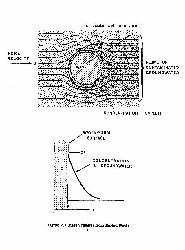
where c is the concentration of the species in ground water, v is the ground water velocity, D the diffusion or dispersion coefficient and A" is the species retardation coefficient. The solubility boundary cotidition is
c = c, (2.1.2)
on the surface of the waste form the concentration is that of the species solubility e, (Figure 2.1), and the other boundary condition is
c = 0 , at infinity (2.1.3)
and the initial condition c = 0, < = 0 (2.1.4)
We shall be concerned with solving this set of governing equations in various forms throughout the remainder of this paper.
2.1.1 Steady-State Results
2.1.1.1 Diffusive
The steady-state form of the equation for for mass transfer by molecular diffusion a low-solubility long-lived species, assuming constant saturation concentration c, in the liquid at the waste surface and assuming that the waste solid is surrounded by porous rock, is
/ = ^ i (2.1.1.1.1)
where / is the fractional dissolution rate of the species, t is the porosity of the rock, D is the diffusion coefficient in pore water, and M is the bulk density of the elemental species in the waste. B is a geometrical factor that can be calculated from the waste-form dimensions. For a spherical waste solid of radius R
B=± (2.-1.1.1.2)
For a prolate spheroid approximating a cylindrical waste form
3£ *=6*log[coth(*,/2)] ( 2 1 1 1 3 )
2
STREAMLINES IN POROUS ROCK
PLUME OF • CONTAMINATED
GROUNDWATER
CONCENTRATION ISOPLETH
WASTE-FORM SURFACE
\*. \ • W W
. W W W I _ i A \ \ \ \ \ | > \ \ S \ \ \ W W W \ • . S \ \ S S \
K W S W N \ \ \ N \ \ \
- \ s C \ S W \ N \ \ S . ' . W W V W W \ W \ \ \ \ \ \ \ W w \ \ \ » \ \ \ \ \ \ \ \ \ \ \ \ \ • . w w w \ \ w \ w v W W W \ \ \ \ \ V , . \ W W \ >\ w w \ A \ S \ \ V A ' , \ \ \ \
-\\\\\\R
CONCENTRATION IN GROUNDWATER
Figure 2.1 Mass Transfer from Buried Waste 3

NMr-fleld MaM Tnoatme
where 61 is the semi-minor axis, £ is the eccentricity, and p is a parameter that defines the spheroid surface
prrcosh-^l/f) (2.1.1.1.4)
These equations for steady-state dissolution rate help focus on the principal parameters that control dissolution rate. It is also important to examine the higher release rates that occur before steady state is reached and that can occur with radioactive species, as predicted by the exact analytical solutions [Chambre et a!. 1982],
2.1.1.2 DlfftwlTe-AdrectlTe
Chambre et al. [1982] have also developed the exact analytic solution for mass transfer when both diffusive and convective transport are important. The mathematical analysis makes use of the known distribution of ground water velocities around an infinite cylinder and through the pores of the surrounding rock, An asymptotic form of that analytical solution, applicable to steady-state mass transfer of a solubility-limited stable species with steady flow around a long waste cylinder of radius lii surrounded by porous rock, and assuming constant saturation concentration c, in the liquid at the waste surface meaning c(Ri) — c,, is
(jrfli)iA/"
where Pe is the Peclet number, given by TT a
P « = ^ (2.1.1.2 2)
Here U is the ground-water pore velocity upstream of the waste solid, and L is the length of the waste cylinder. The other boundary condition is c(oo) = 0. The analytical solution does not depend on boundary-layer approximations.
Equations for the steady-state dissolution rate that are similar in form, but not identical, to Eq. (2.1.1.2.1) have been obtained by others [Neretnieks 1978; Kerrisk 1984; 1985; Scott and Koplik 1984] using boundary-layer approximations. However, only the exact time-dependent solution provides a criterion of validity of the asymptotic steady-state equation. Ignoring the limit of validity and applying the steady-state asymptotic equation, or its equivalent [Kerrisk 1984; 1985; Scott and Koplik 1984], to predict mass transfer rate at the very low velocities expected in wet-rock repositories is not valid and will give nonconservatively low estimates of the dissolution rate.
Correct and incorrect predictions of fractional dissolution rate over a wide range of Peclet numbers are illustrated in Figure 2.2, calculated for solubility-limited mass transfer. The values at near-zero velocity have been calculated from the equations for diffusion from a prolate spheroid, with dimensions that approximate a finite cylinder. Incorrect extrapolation of the Pe 1/ 2 dependency from the high Pe region to the pore velocities of a few millimeters per year, expected in the tuff and basalt repositories, can result in underestimates of the release rate by several orders of magnitude.
For an assumed waste radius of 15 cm and an upper-limit value of the diffusion coefficient of 10~e
cm2/s, which neglects tortuosity corrections, the ground-water pore velocity must be about 1 m/a or greater for the steady-state equation to be applicable. For lower velocities the equation for diffusion-controlled release is applicable.
4

10^ 3
10 s =
10* =
10 I-7 =
1 0 8 =
10 s
DIFFUSION-ADVECTION
100YR,K = 100
STEADY-STATE +'
* '
L*''\
I. .-. .IIKlriii /•'. I f T I I I N; &X III i K / r n i : ' (K.rrifk) /» :;'J.-ni-/yr < 0.1 II. -• 18 (KIII
NOT VALID
i ilium—i i limn—i 111urn—i i IIIIIII—i niiiin—i i IIIIIII—i i MIIIR 10' 3 10- 10 -1 10° 10 1 10 2 10 3 10 4
GROUND WATER PORE VELOCITY, cm/YR
Figure 2 2 Valid and Invalid Extensions of Dissolution Rate as Function of Ground-Water Velocity

Naur-Maid Man* Tfcanafar
2.1.2 Transient Results Time-dependent mass transfer rates have been obtained for both diffusive-advective systems and
diffusion-dominated systems.
2.1.2.1 DlffiulTe-AdrectiTe
Chambre and Pigford [1984] give the following equation for the time-dependent mass transfer rate per unit length of an infinite cylinder for a radioactive species with a constant-concentration boundary condition, provided the Peclet number is greater than 4
V JT \ m(w) Vo »>(»') 1
where fis = KXR/U is the Thiele modulus for convective mass transport, and K(x) is the complete elliptic integral of the second kind, and m(a) = <Jl - exp(-4w) and w = Ut/KR
The equation for the time-dependent fractional rslease rate for a long cylinder in ground water where the Peclet number is greater than 4 is
/ = 8 € C , f S + / / £ ) ( • " y " + ° > / V ^ H ^ ^ I , t/^>4 (2.1.2.1.2) (xR)3i2tf \ m(c?) y 0 m(w') j
Typical results for a waste solid surrounded by porous rock, with ground water flowing at pore velocity of 1 m/a, are shown in Figure 2.3, where the normalized fro. aonal dissolution rate f/c, for a stable species is plotted against the time since the waste is first exposed to ground water at the waste surface.
Tiie early rate of mass transfer will be high, and it will decrease as the concentration profile penetrates farther from the waste surface. With no decay, and for the parameters chosen for Figure 2.3, steady state is reached in as little as a year or not until a few hundred years, depending on the magnitude of the retardation coefficient K. Greater sorption retardation increases the time to steady state, and it increases the transient dissolution rate because sorption steepens the transient concentration gradient. Advective transport shortens the time to reach steady state.
Radioactive decay can increase the rate of mass transfer by steepening tht concentration gradi^t near the waste surface. This is shown in Figure 2.4 by curves for various values of the modified 'Thiele modulus fio. Increasing the Thiele modulus from zero, to 10 for no decay causes a more than fourfold increase ;n the steady-state dissolution rate, and it decreases the time to reach steady state. For a mixture of stable and unstable isotopes of a given element, the appropriate half life is the effective half life of the isotcpic mixture at the time the decay correction is to be applied. Decay corrections are more important when mass transfer is controlled by diffusion, i.e., when the pore velocity is so low that convection does not affect dissolution.
2.1.2.2 Dlffuslre
Chambre et at. [1985] have obtained the transient solution for mass transfer from prolate spheroids including spheres and cylinders, over all times of interest. The complete solution is complicated, and the
6

O • «
10'
10
lO'R
. 6 2 i
id 3 1
I 1 1 1 1 1 1 1 U =0
— x = o R = 44 cm e = o.oi
—
s^KHO 4
D = !0" 5cm 2/s -
-
^ S S " N ^ —
-
i i l l i i 1 I 10" :o~ 10 I 0 2 I0 3
Time, years 10' I 0 5 10s 10'
Figure 2.3 Normalized Mass-transfer Rate as a Function of Time and Retardation Coefficient, Diffusion from a Waste Sphere

IO-> I 10 Time, yeors
Figure 2.4 Normalised Mass-transfer Rate as a Function of Time and Damkdhler Number, Flow around a Waste Cylinder
8
Near-Held Maaa Transfer
governing equations are in prolate spheroid coordinates. Therefore, only the results for a sphere will be shown here. The surface mass flux from the waste sphere for a stable species is
*(«,0) = iH=Hi/^£- + l>, t > 0 (2.1.2.2.1)
2.2 Dissolution from Waste Into Rock: Solid-Liquid Reaction Rate
The analytical solutions discussed above for solubility-limited mass transfer have a clear meaning for a single-component waste solid that has a well-defined solubility appropriate to the chemical environment at the waste surface, Solubility is a conservative upper-limit boundary concentration, if effects of colloids can be neglected. The result is a bounding estimate of the release rate from the waste solid and is not dependent on the particular chemical form of the waste solid unless that chemical form itself affects the solubility of the single-component species. Effects on other constituents within the waste solid will be discussed later.
In many studies it has been assumed that waste forms can be developed that will perform better in a repository because of low rates of chemical reaction of the waste solid with ground water. The proposition is reasonable but has been made without quantification of the effect of chemical reaction rate on the performance of a waste solid in a repository. In the mass-transfer analyses discussed above for solubility-limited species, it has been implicitly assumed that the solid-liquid reaction rate is rapid enough so that the dissolved material is at, or very near, the solubility limit at the waste surface. Actual chemical reaction rates do not enter those analyses, and the bounding results are not affected by factors which can affect solid-liquid reaction rate, such as interior cracks in the waste solid, devitrification if a glass, and other such mechanisms that could increase the surface area for solid- liquid reactions.
To illustrate an approach to determine the effect of solid-liquid reaction rate on the rate of mass transfer to ground water in a geological environment, Zavoshy ei al. [1985] developed the analytical solution for the rate of diffusive mass transfer of a dissolved waste into surrounding porous rock, using chemical reaction rate as a boundary condition instead of assuming a solubility-limit boundary concentration. Leach-rate data [Pederson, Cuckwalter and McVay 1983] for borosilicate glass waste suggest that the solid-liquid reaction rate can be approximated by a zero-order forward reaction and a back reaction that is first order with respect to the concentration of dissolved silica. Assuming low ground-water velocity so that mass transfer is controlled by diffusion, the governing equation for diffusive mass transfer is
K T t = D h T r ^ t>0,R<r<oc (2.2.1)
with the initial condition
c(r,0) = 0, R<r<oo (2.2.2)
The continuity boundary condition at the waste-liquid interface in a repository specifies that the current of dissolved species at the waste surface equal the net rate of dissolution by solid-liquid reaction. Assuming that the reaction rate is given by a zero-order forward reaction and a first-order back reaction.
^ g f i ^ - S M ) , <>o (2.2.3)
9

Near-Bald Maas IVanafar
where jo is the experimental forward reaction rate of the dissolved species per unit surface area. The forward reaction rate is measured when the surface is in contact with a liquid that contains none of the dissolved species being considered in Eq. (2.2.1).
Using the above boundary condition together with the diffusion equation and with the other side condition c(co, () = 0, i > 0, we obtain the time-dependent concentration c(R, r) in the liquid adjacent to the outer surface of the waste
c W r ) = o t
Q ( 1 - e r e r f C ^ r ) (2.2.4) 1 + Or
and the time-dependent rate of mass transfer into the rock at R
.. . . l + «eTerfcv/r . . . . . j(ro,r) = j 0 l + a
v (2.2.5) where the dimensionless time r is defined as
r - 0 + «)'P< , 2 2 f i .
The dimensionless "flux ratio" a is defined as
• = £r <"*> eDc, and can be interpreted as
forward reaction rate per unit area at R Ct zz
steady — state diffusive mass transfer rate at R We can interpret the forward reaction rate jo in terms of a reaction-rate constant fa
(2.2.8)
jo = he, (2.2.9)
which results in
° = ^ (2.2.10)
Thus a is a Thiele modulus.
At steady state the concentration and mass-transfer rate at the surface are
c(R,oo)=ctT2— (2.2.11) 1 + a
and
i ( r t . ° o ) = j ^ (2.2.12)
Eq. (2.2.11) and (2.2.12) show that when the flux ratio a is large c(R, oo) = c, and j(.R,oo) w tDc,/a. Under these conditions the net dissolution rate is controlled by diffusion in the exterior field. When a <C 1 the surface concentration c(R, oo) is much less than the saturation concentration, and the net mass-transfer rate is controlled by the solid-liquid reaction and is equal to jo. For intermediate values of a one must use Eq. (2.2.11) and (2.2.12).
10

N«ur-(Uld Maw TVanafor
Another quantity of interest is the time t, necessary for the mass flux at the surface to reach within five percent of the steady-state value. From Equation (2.2.6) it is found that
u-{ 0 for a < 0.01; — ' (2 2 13)
4 x 10 2 A'7? 2 /TL» for a > 1
Chambre has shown that if radioactive decay is included in Eq. (2.2.1) the above results are affected by both decay and retardation. The analysis of the surface concentration and dissolution rate, including the effects of species decay within the waste form, has also been treated.
The normalized dissolution rat? j(R,r)/ja and the normalized surface concentration c(H,r)/c, are shown in Figure 2.5 as a function of the dimensionless time r and the dimcnsionlcss parameter a.
To illustrate, we assume a waste glass cylinder of radius 0.15 m and length 2.4 m, resulting in an equivalent sphere of radius 0.44 m. From the laboratory leach data of Pedcrson et al. [1983] for PNL 76-68 borosilicate glass we derive the following effective values for silica at 90 C
jo= 1 . 1 8 g S i 0 2 / m s - d a y
c. = 200 g S i 0 2 / m 3
For an estimated diffusion coefficient of silicic acid in water at 90 C of 2 x 10" 2 m 2 /d and neglecting tortuosity corrections, and for a rock porosity of 0.01, we estimate asio, = 1240. Assuming no sorption of silica on the rock (K — 1), the estimated time to steady state is 320 years. From Eq. (2.2.11) c(fl,oo) = 0.999c, for silica. The steady-state mass transfer of silica will be controlled by exterior-field diffusion, and assuming saturation concentration c, of silica at the waste surface is not only conservative but is also realistic.
Figure 2.6 shows the normalized surface mass flux of silica and the normalized surface concentration as a function of the dimensionless time and chronological time (. Also shown are the results predicted by assuming that saturation concentration always exists in the surface liquid, as in our earlier conservative estimates of mass-transfer rate in Section 2.1.2. For assumed constant saturation the early mass-transfer rate is infinite, a result not physically reasonable. It is in these early times that the solid-liquid reaction rate is important for the dissolution of a low-solubility solid matrix. The actual surface concentration is initially zero, and it grows with time at a finite rate determined by the solid-liquid reaction rate. Within about seven minutes after bare glass waste has been placed in contact with saturated rock (c = 0.01) the concentration of silica in the surface liquid will have reached 82 percent of saturation and the mass-transfer rate will be within 5 percent of that predicted for constant saturation at the surface, assuming no silica sorption in the rock. If silica sorbs with an assumed retardation coefficient of 100, this time is increased to 700 minutes.
The time to reach near-saturation concentration will be longer if there is stagnant liquid between the waste surface and the exterior porous medium. This time delay is easily added to the theory because the intervening liquid is likely to be well mixed.
Van Luik et al. [1987] list values of jo for unirradiated and irradiated U 0 2 in deionized water and in brine at various temperatures. They adopt a conservatively low value of
jo = 0.005 g /m 2 -day
11

Dimeniionless time, r = (x + ayDt KIP
Figure 2.5 Normalized Dissolution Rate and Surface-Liquid Concentration as a Function of Dimension-less Time for Varllous Values of the Flux Ratio

I
1 0.2-
Dimetukraless time, r = (x + «) aJPt JiCR3
-0 .8
1.0
-0 .2
-0.4
—0.6 "8
£
Figure 2.6 Normalized Dissolution Rate and Surface-Liquid Concentration of Silica from Borosilicate Glass as a Function of Time, Compared with Dissolution Rate for Constant Saturation Concentration at the Surface

N*ar-fl«ld Mass Transfer
Assuming that uranium dissolution obeys a simple concentration dependence as described in Eq. (2.2.3), adopting uranium solubilities ranging from 2 x 10~2 g/m 3 at pH 11 to 2 x 10~8 g/m 3 at pH 6 [van Luik et al. 1987, p 4.77], and for other parameters the same as used in the above example for silica, we obtain an estimated flux ratio for the spent-fuel matrix
a - 5 x 10⁴ to 5 x 10 1 0
which is about one to seven orders of magnitude greater than that estimated for silica from borosilicate glass. If these data are correct, uranium dissolution in a basalt or granite repository is likely to be controlled by exterior-field mass transfer and not by chemical reaction rate. More data arc needed on solid-liquid reaction rate as a function of concentration of dissolved uranium and of temperature.
A more recent result [Chambre et al. 1988] shows the relationship between steady-state mass transfer from a spherical waste solid, the exterior flow field and chemical reaction or leaching rate, The steady-state governing equation is
dc _ 1 d ( tds\ _ ,„ _ . . . Vd; = DriTr{rTr)> * < r < 0 ° < 2 J U 4 >
The boundary and initial conditions of (2.2.2) and (2.2.3) apply. The result relates the Sherwood number, Sh, and the Peclet number, Pe, with the square of the Thiele modulus, a, which is defined as the ratio of the forward reaction rate per unit area at A to the steady-state diffusive mass-transfer rate per unit area at R.
Sh = g (2.2.15)
P e = ^ (2.2.16)
- J g (2.2.17)
Here h is the mass-transfer coefficient for the spherical waste surface
h _ j(R,oo) c(R, co) - c(oo)
where c(oo) is the ambient concentration of the dissolving constituent in ground water, here taken to be zero. The following interpolation formula is valid for the entire range of Peclet numbers.
„, 1 + 0.5\/0.5jrPe + 0.5Pe „^,_ ,„„ ,„ , Sh ss a . • - —-j , 0 < Pe < oo (2.2.18)
1 + 0 W0.5irPe + 0.5Pe + a(l + 0.5v/0.5»Pe) ~ v ;
This formula has been tested by comparing it with two other solution methods and shown to provide predictions reasonably close to the other methods. For very small Peclet, when advection is unimportant, the Sherwood number becomes
S h - y - ^ , P e - 0 (2.2.19)
When the Peclet numbers are very large,
Sh -t «, Pe -* cc (2.2.20)
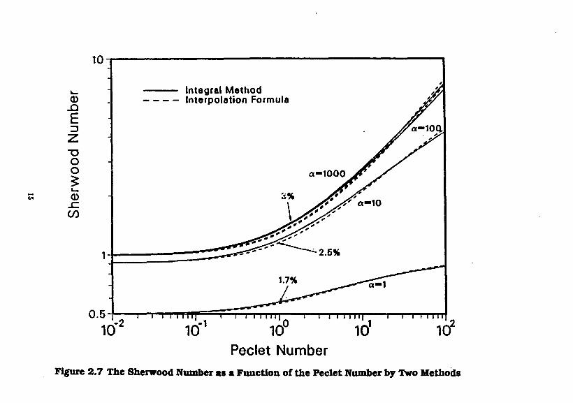
Figure 2.7 shows the Sherwood number as a function of the Peclet number, for various values of the square of the modified Thiele modulus a, obtained by the interpolation formula, Eq. (2.2.18) and an integral
14
10
CD
£ 3
T3 O O
CD sz CO
Integral Method Interpolation Formula
0.5-J 1—i i i i ni l i—i i i i m i
10"2 10" 10° i i i i n i l i i i i i H I
J 10 10 Peclet Number
Figure 2.7 The Sherwood Number as a Function of the Peclet Number by Two Methods
Naar-fldd Maw Trmmfw
approximation method. In the range of 0.01<Pe<l it can be seen that the Sherwood number is almost constant for fixed values of a, see Eq. (2.2.19). In this same range of Peclet number, a hundred-fold increase in a, say from 10 to 1,000, results in only a 10 per cent increase in Sherwood number. At Pe = 100, increasing a from 10 to 1,000 almost doubles the mass-transfer rate. For 40<Pe< 108, well outside the range of Peclet numbers and flow speeds anticipated in geologic repositories, and for values of a of about 100 and greater, the Sherwood number is approximately proportional to the square root of the Peclet number, showing that diffusive-advective mass-transfer controls [Chambre ti al. 1982]. At even larger Pe, see Eq. (2.2.20), well beyond the range of this figure, the curves level out when the exterior-field mass-transfer is so intense that chemical reaction rate controls the dissolution rate. For a—I, as can obtain for small separated grains of a dissolving solid or for dissolution at very low temperature, chemical reaction rate reduces the influence on the modified Sherwood number over the entire range of Pe and causes the dissolution rate to be less affected by advective transport.
For the ground-water velocities, waste dimensions, and temperatures expected in geologic repositories, the steady-state dissolution of borosilicate glass is predicted to be controlled by exterior field mass transfer. The ground-water velocities required for chemical-reaction rate of borosilicate glass to control dissolution rate are far beyond any reasonably expected in a repository. Chemical reaction rate and rate of diffusion from a borosilicate glass waste form <: an control the dissolution rate at temperatures much lower than are expected in a nuclear waste repository, i.e., when a <1. Preliminary data indicate that similar conclusions may be applicable for spent fuel, but more data are needed on solid-liquid reaction rate as a function of concentration of dissolved uranium and of temperature.
2.3 Mass Transfer from Waste Into Backfill and Rock
2.3.1 Transient Diffusion-Controlled Dissolution
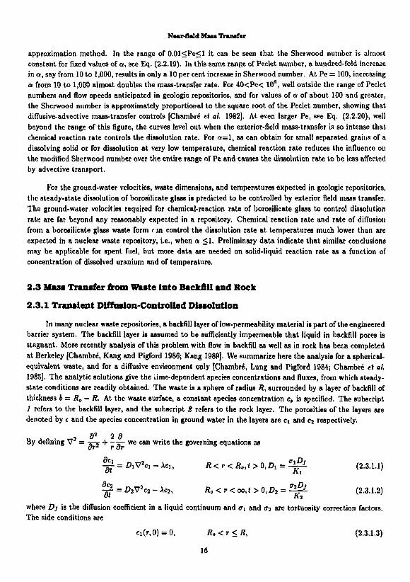
In many nuclear waste repositories, a backfill layer of low-permeability material is part of the engineered barrier system. The backfill layer is assumed to be sufficiently impermeable that liquid in backfill pores is stagnant. More recently analysis of this problem with flow in backfill as well as in rock has been completed at Berkeley [Chambre, Kang and Pigford 1986; Kang 1989]. We summarize here the analysis for a spherical-equivalent waste, and for a diffusive environment only [Chambre, Lung and Pigford 1984; Chambre et al. 1985]. The analytic solutions give the time-dependent species concentrations and fluxes, from which steady-state conditions are readily obtained. The waste is a sphere of radius ft, surrounded by a layer of backfill of thickness b= R0 — R. At the waste surface, a constant species concentration c, is specified. The subscript 1 refers to the backfill layer, and the subscript S refers to the rock layer. The porosities of the layers are denoted by t and the species concentration in ground water in the layers are ci and c 2 respectively.
„ , , . „ , a2 2 a . , By denning V = rs-j + ~s- we can write the governing equations as
^ • = 0iV a Ci-Aci, R<r<R„,t>0,D1 = ^i- (2.3.1.1)
~ = J92V2c2 - Xa, Ro<r<oo,t>0,D2 = ^ - (2.3.1.2)
where Dj is the diffusion coefficient in a liquid continuum and <ri and a2 are tortuosity correction factors. The side conditions are
ci(r,0) = 0, R0<r<R, (2.3.1.3)
16

NMr-fiald Maw Transfer
ci(r, 0) = 0, R„<r <oo (2.3.1.4) c1(R,t) = c„ t>0 (2.3.1.5)
d(R0,t) = c2(R„,t), i>0 (2.3.1.6)
-WD,?P- = - w D , ^ at r=ft„, * > 0 (2.3.1.7) or or c2(oo,*) = 0, t > 0 (2.3.1.8)
The solution to (2.3.1.1) through (2.3.1.8) is given in Chambre et al. [1985]
-DiOa
£ l M = f(r) + r 7 ^ r « ^ + «- A < r ' " , ' ' v /(r, i>)<ft>, « < r < ; e o , « > 0 (2.3.1.9) c, y 0 l + aja- -A) I + ^ T J ^ I )
where
, , . , J ' t W ) .,_ > p f l c ' i t ^ N y B i n ^ r - / ? ] ) a,-,/FJW r l + 6(R/Roy
#(•?) = 4>7Cos(i?6) + -2-^-sin(?)6) is
+ [ft t^sinW)] 2 « = c 2
If A = 0 in (2.3.1.9), we obtain the solution for a stable species.
The above equations are applicable for a radioactive species with no decay precursor and for diffusion-dominated mass transfer through the backfill and the surrounding porous rock.
dc With the concentration profile c(r, t) known, the surface mass fluxes t<rDj-r- at the waste surface and at the backfill/rock interface can be computed. A computer program, UCB-NE-101 [Lee 1989a] implements eq. (2.3.1.9) and is available from the National Energy Software Center.
Illustrative results [Chambre et al. 1985] for species limited by solubility are shown in Figures 2.8-2.10. Figure 2.8 shows the time-dependent mass transfer rate (mass/time) of a stable species divided by the saturation concentration of that species, assumed to exist at the inner surface of the backfill. A similar normalized rate of mass transfer across the backfill-rock interface is shown by the broken curves. A retardation coefficient of 1000 is assumed for backfill and rock. Curves for two values of the backfill porosity are shown, corresponding to backfill-to-rock porosity ratioe of unity and 20. During the early times of the transient the higher backfill porosity greatly increases the dissolution rate, because the early resistance to mass transfer is entirely within the backfill. The mass-transfer rate into the rock closely approaches that into the backfill after about 104 years, and steady state is reached after about 105 years. The steady-state mass transfer rate is little affected by backfill porosity, as demonstrated in Figure 2.9.
Figure 2.9 shows the effect of retardation on mass transfer rate of a stable species, for a backfill-to-rock porosity ratio of 20. Retardation increases with increasing sorption, which steepens the transient concentration gradient and increases the rate of diffusive mass transfer. Steady-state rates of mass transfer are not affected. For a given backfill retardation, increasing sorption by rock increases the maximum rate of mass transfer into the rock, showing that the rock properties and finite backfill must be included in the
17

i IIIIIIII i IIIIIIII i IIIIIIII i IIIIIIII i IIIIIIII i IIIIIIII i uiiii. 10° 101 10 103 104 105 106 107
Time, years Figure 2.8. Normalized mass-transfer rate as a function
of time and backill porosity 18
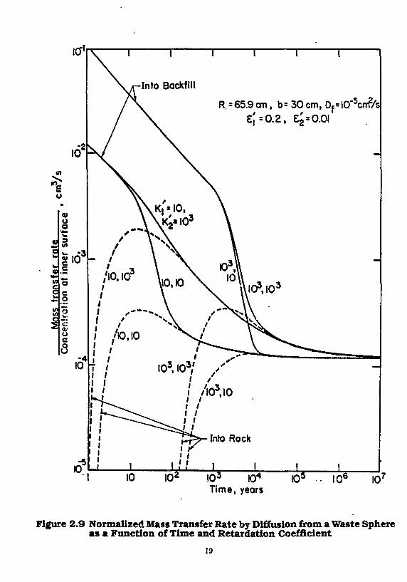
R. = 65.9 cm, b = 30 cm, Df=10*5cnf/s
I 0 3 KD4
Time, years IQ5 10'
Figure 2.9 Normalized Mass Transfer Rate by Diffusion from a Waste Sphere as a Function of Time and Retardation Coefficient
19

10
• -3 Sio 3
c o o . 4
<w u c o (J
id 9
-5„„2/
-Into Backfill
R. =65.9 cm, b=30cm, Df=IO'5cmVs £', = £2 = 0.01, K[=K 2=I0 3
T|/ 2=l5.3yr
CD a!4xl0 6yr,//
V //5730 yr
frV ll
* i
Into Rock
Jj.
5730 yr 5_73p_y_r
2.14xlQ6yr 00
t 1 J_ 10 10' I0 J SO*1
Time, yeors 10' 10° 10'
XIL«4(2-3«tS
Figure 2.10 Normalized Mass Transfer Rate by Diffusion from a Waste Sphere as a Function of Time and Half Life
20

NMT-0«1<] Mm Tmmt*r
analysis, as has been done here. The time for the maximum rate of mass transfer into the rock depends mainly on the backfill retardation, for the parameters assumed here.
Figure 2.10 shows the effect of radioactive decay on the time-dependent mass transfer rate for various assumed half lives of the diffusing species. For neptunium-237, with a half life of 2.1 x 10e years, corrections for decay are minor. For , 4 C, with a half life of 5730 years, decay not only increases the rate of mass transfer into the backfill, because it steepens the concentration profile, but it also increases the transient and steady-state rates of mass transier into the rock. For a radionuclide half life as short as 15.3 years, decay considerably increases the mass transfer rate into the backfill, but the half life is short enough that the species all decays while diffusing in the backfill. Thus, there is a range of half lives for which the rate of mass transfer into the rock is greater than the steady-state value for no decay. As illustrated here for M C , some radionuclides important in repository performance analysis will fall within this range.
Previous backfill analyses [Nowak 1979; Aim et «/, 1982a, !>] have calculated the "breakthrough1' time for a stable species at a specified distance in infinite backfill and have used that time to estimate the amount of radioactive decay that will occur during diffusion through finite backfill in a repository. This has led to considerable overestimates of the possible retention of radionuclides in backfill, as has been demonstrated in Figure 2.10 for H C . Mass-transfer analysis that take into account the diffusive properties of the rock should be used to predict release of radionuclides through finite backfill.
2.3.2 Steady-State Mui Transfer Through Backfill into Flowing Ground Water
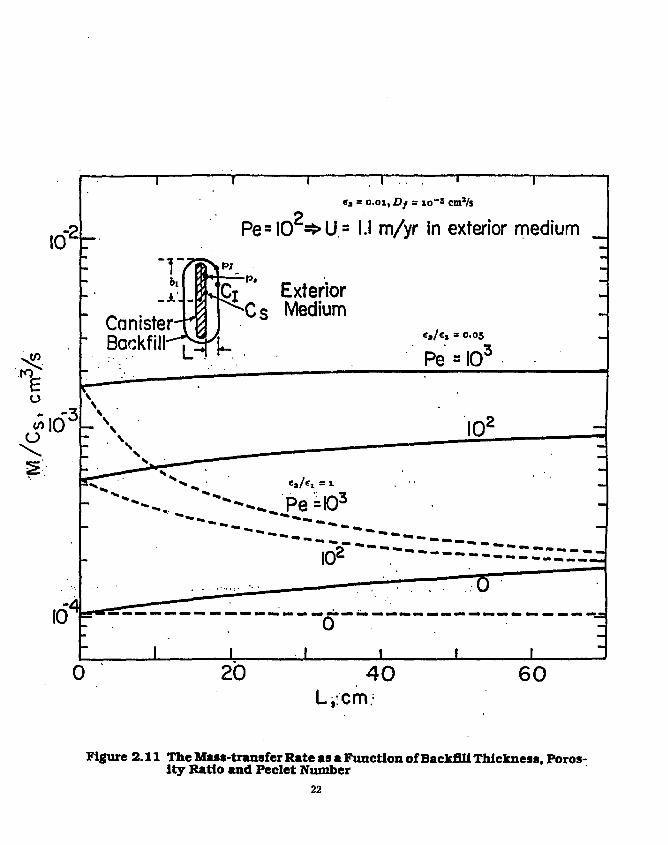
For the case of a waste container surrounded by a backfill layer in flowing ground water, we give a solution of the steady-state mass transfer rate for a stable species. Here the waste is approximated by a prolate spheroid with a semiminor axis b\ at the backfill/rock interface, as shown in the insert in Figure 2.11. The prolate spheroid coordinate is p, defined in eq.( 2.1.1.1.4), and p = p, is the location of the inner surface of the backfill and p = pi is the interface of the backfill and the rock. The species is at solubility c, at the surface of the container. The backfill is assumed to be sufficiently impermeable that liquid in the backfill pores is stagnant. Ground water flows at a velocity U in the porous rock. The mass transfer rate is
(W«i«ri) [C(P . )" <2.(Pf )]coah(pj) + [Sh(Pe)]"1
where C(p) = In (coth p/2) (2.3.2.2)
The mass-transfer rate in the exterior medium is proportional to the Sherwood number, as follows,
i a.(c,)Lh(<,) [ 1 +ifi . ( t , fe .hfa)]' Pe »mall
^/£tanh(c/), Pe>4cothp,. (2.3.2.3)
Figure 2.1.1 shows the mass-transport rate as a function of backfill thickness, the backfill/rock porosity ratio, and Pe, assuming <ri — <rt = 1. For equal porosities of backfill and rock, backfill reduces the mass transfer rate because of the assumed zero flow in the backfill. For a given backfill thickness, decreasing the backfill porosity decreases the mass transfer rate. A decrease in the backfill/rock porosity ratio from 20 (solid curves) to 1 (broken curves) causes much of the exterior-medium resistance to shift to that of the backfill. For a backfi!l/rock porosity ratio of 20, increasing backfill thickness causes the rate of mass transfer into the rock to increase, because low-porosity rock is being replaced with more porous backfill. Increasing the ground-water
21
10 r2
i , i .. . — i — ea = o.oi, Df = io"5 cm'/s
Pe=IO =>US I.I m/yr in exterior medium _
17SN
Canister . M . Backfill-^[^V
PI - p .
!Cj Exterior Cs Medium
e s / « x = 0.05
Pe = I03
* - -^ ^
' " ^ - ^ P e = l 0 3
******** " " " * * * * • - « » . . , ""
0 20 4 0 60 L,:cm.
Figure 2.11 The Mass-transfer Rate as a Function of Backfill Thickness, Porosity Ratio and Peclet Number
22

Near-field Man Ttmnafer
flow outside the backfill from the pure diffusive transport of Peclet of zero to a Peclet of 1000 shows an expected increase in the mass transfer rate.
2.4 Mass Transfer Into Fractured Rock
In constructing nuclear waste repositories in rock, it may be necessary to place a waste package in a hole intersected by one or more rock fractures, or rock fractures may develop after waste packages have been emplaced. Predicting the spatial and temporal distribution of contaminant species can be important, because such fractures can be preferential pathways for released radionuclides to re-enter the biosphere.
Recently Aim, Chambrc and Pigford [1989] obtained the solution for dissolution of species in a diffusive environment from a waste cylinder intersected by a planar rock fracture (Figure 2.12). Consider an infinitely long waste cylinder with radius H\, surrounded by infinite rock containing a planar fracture intersecting the cylinder and normal to the cylindrical axis. We conservatively assume bare waste and the surface concentration is at the solubility limit of each species. The fracture width or thickness is 26 and complete mixing across the fracture width is assumed. Retardation is treated by equilibrium sorption. The mass balance for the time-dependent species concentrations in the rock and in the fracture are
*'fuTs('t) + 6 'S£- 1*' <" '>M>*„«>o |W| dci
in which q{f,t) = -tiDi g . t>Q,r>Ri (2.4.3)
is the diffusive flux from the fracture to the rock through the interface [M/Ls-t] where subscript / denotes the rock subscript S denotes the fracture r is the distance from the centerline of the waste cylinder [L] £ is the distance from the rock/fracture interface [L] t is time [t]
The side conditions are
c3(r,0) = 0, r > « ! (2.4.4) ci(r, i ,0)=0, r>Ruz>0 (2.4.5) C3{Ri,i) = c„ i>0 (2.4.6) C3(oo,t) = 0, « > 0 (2.4.7)
cl(Ruz,t) = c„ i > 0 , t > 0 (2.4.8) £1(00,2,0 = 0, z > 0 , ( > 0 (2.4.9)
ci(r,0,0 = cs(r,0. r>R1,i>0 (2.4.10)
—\ =0 , f > f l i , £ > 0 (2.4.11)
23

* /
Waste
M U t M W M i t^L.
Hock
Figure 2.12 Waste package intersected bj a fracture
24

Naur-field MOM Ituwfw
By introducing the following transformations
_ z
isM. 4 , M
tf.K?
Oj = :—r—
ca(»',0 = —i—
c\(r,z,t) = r c«
q = Riq
Ci£»lC!
where t is the Fourier number, eq. (2.4.1) and (2.4.2) can be made dimensionless as
dc3 _ Aj)_ dc3 q dt ~ ^ar l ^ ^^ , ~ A C 3 ~67 ,
dt ~ r dr V dr J
r > l , i > 0
r > l , z > 0 , i > 0
(2.4.12)
(2.4.13)
(2.4.14)
(2.4.15)
(2,4.10)
(2.4.17)
(2.4.18)
(2.4.19)
(2.4.20)
(2.4.21)
(2.4.22)
The full derivations and solutions are shown in Ahn, Chambre and Pigford [1989] and only the analytic solution will be given here. The normalized diffusive flux from the waste cylinder to the fracture is
*•>--!? , = v T ^ | ^ - ; l ' i ( 0 ' ' ) + '>(»•') + W,I)1, ! >0 (M23)
And the normalized diffusive flux from the waste cylinder directly into the rock is
where
1 /f0(VA) T
Wow = \Z[̂ o(«)]2 + [y0(5)]2
e - e r f c ( ^ + ^ )
25
t i / , ,, 1 (A-l)A
2 > 0,<>0 (2.4.24)
(2.4.25)
(2.4.26)
(2.4.27)

N*ar-0*ld Man Tnsutt
* ( * i M ) =iii^Tr"^ G5?-**) ( 2 A 2 8 )
^ 3 ( S ; , , 0 = U e - ^ e r f ( ^ ) (2.4.29)
(2.4.31)
(2.4.32)
P=\fl-ibl(A-l)8* (2.4.33)
ji? = a JA + A (2.4.34)
111 = * s + A (2.4.35)
F(*) = e*aerfc(*), (2.4.36)
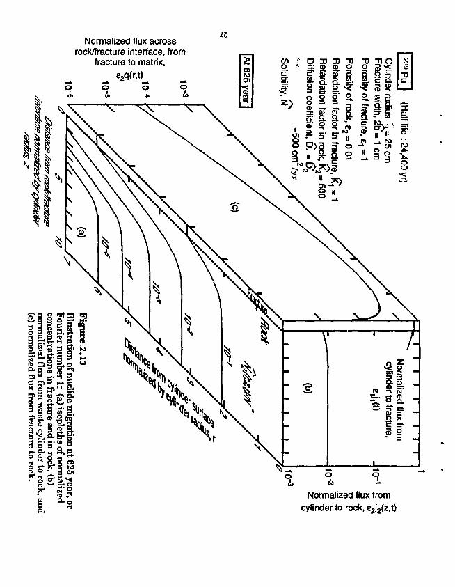
The results are illustrated in Fig. 2.13, which shows instantaneous concentration isopleths, mass flux across the fracture surface, and mass fluxes from the waste into the fracture and into the rock matrix. The diffusion coefficient D is conservatively chosen as that for a liquid continuum. Concentrations are normalized to the quantity Dc,/R\ defined in Fig. 2.13. The mass flux into the fracture is calculated to be about two orders of magnitude greater than that into the rock matrix, beause of the assumed hundredfold greater porosity in the fracture.
2.5 Temperature Effects
In the foregoing analysis, we have made the assumption that the nuclide and geologic properties are constant in space and time. In a geologic repository of nuclear waste this will not be true. Heat from buried waste will have significant influence on transport processes. The parameters that characterize transport, such as diffusion coefficient, solubility, and retardation coefficient, are functions of temperature. We will now show how variations in such parameters can be treated, through an example of temperature dependence [Pigford, Chambre and Zavoshy 1983; Chambre ei «/. 1984; 1985].
Let the temperature as a function of space and time be known. If we know the functional dependence of the diffusion coefficient, solubility, and retardation coefficient on temperature, we can obtain their time dependence also. We will now show how to treat the variation of diffusion coefficient, solubility, and retardation coefficient as functions of time. Let c(r,t) be the concentration of the species in ground water, diffusing from a waste in contact with rock of porosity e, with no backfill layer. The governing equation for diffusive transport is
» = D{t)±£(r*£) - /f(0Ac, R < r < oo,t > 0 (2.5.1)
Here K(i),D(t) and c,(i) are time-temperature dependent functions with reference values KQ,DQ, and c,0, R is the radius of the waste spbare, and A the species decay constant. The initial condition is
c(r,0) = 0, r>R (2.5.2)
26
Normalized flux across rock/fracture interface, from
fracture to matrix,
iz
Normalized flux from cylinder to rock, e^z.t)
N*u--flald MM* Ikaoafw
and the boundary conditions are c(R,t) = c,(t), t>0 (2.5.3)
c(co,0 = 0, « > 0 (2.5.4)
Now we define two dimensionless functions f(t),g(t) as
K(0 K o ' ( 0 ( 2 5 5 )
*(()«.(*) = Co/(0. « > 0 (2.5.6) representing the known time dependence of K(t)c,(t) and D(t)/K{t) respectively. The solution is given in terms of the mass transfer rate m(t\ A) from the waste sphere per unit area
where
/(r) = /(<(r))e*«W r«) = J ^ j\{t')dl<, t>0 (2.5.8)
To obtain the diffusion coefficient as a function of temperature, we use the Nernst-Einstein equation
Dfi/T = constant (2.5.9)
where fi is the absolute viscosity and T the temperature. The above approach was illustrated for the case of simultaneous dependence of solubility and diffusion coefficient on temperature in congruent dissolution from borosilicate glass [Chambre et al. 1985].
From data on temperature-dependent diffusion coefficients and silica solubilities, we predict the time-dependent dissolution rates of silica from borosilicate glass waste in basalt, for K — 1 and 100. Normalizing to the dissolution rate m that would occur at steady state and ambient temperature 58 C yields the results in Figure 2.14. The dissolution rate at 1 year and K = 100 is 154 times the steady-state ambient rate because of the temperature-increased solubility and diffusion coefficient and because of the steeper concentration gradient at the waste surface near the beginning of dissolution. The transient gradient and dissolution rate are reduced in the absence of sorption (K = 1).
2.6 Effect of Non-linear Sorption on llaia Transfer Through Backfill In the previous analyses we have assumed linear sorption in the backfill, as expressed by a retardation
constant independent of concentration. However, if the species concentration in the liquid phase is sufficiently large so that the solid phase cannot absorb all the species, then sorption saturation is said to occur. Some data show nonlinear sorption in bentonite, with a tendency towards saturation of the sorption sites [Chambre et al. 1985], For such backfill materials, the mass-transfer characteristics can be far different than those analyzed above for linear sorption, corresponding to a concentration-independent retardation coefficient.
A sorption distribution coefficient K* relates c the species concentration in the liquid, and c„ the mass of the species adsorbed on the solid phase per unit bulk dry mass of the porous material
Ki = ^ (2.6.1)
*(U) - - £ > ( 0 e - ^ - - m t )
28

10
k . M = 470 kg K=100
>» R =0.42 m
& •* *
•5 10
I Dis
solu
tion
O •
^S^ft)
Frac
tiona
constant T
Frac
tiona
i 1 I I 1 10 10 10 10 10 105
Time After Emplacement, years
10
Figure 2.14. Effect of Repository Heating on the Rate of Silica Dissolution
29

Near-fUId MM* Tnaaatar
A Langmuir isotherm can be used to account for sorption saturation. Figure 2.15(a) shows T the saturation concentration in the solid phase. The Langmuir isotherm can be approximated by two linear segments: for c < c*, we have the common linear isotherm, and for c > c*, the solid is saturated and c„ = T for all c [Lung et at. 1983]. c* is called the critical concentration.
The retardation coefficient K is defined as
tf(C) = l + A^A-,(c) (2.6.2)
where e is the backfill porosity and p is the bulk density. Assuming diffusive transport in the liquid phase and none on the solid, the governing equations for one-dimensional transport of the species are
^ = Z > ^ - * ( C , c . ) - A « (2.6.3)
fcifil = +*(c, c.) - A[l - <)c. (2.6.4)
where 4>(c,c„) is the interphase reaction rate. By adding (2.6.3) and (2.6.4) we get
^[ec + (1 - e)c] = D^- - Afec + (1 - e)cj (2.6.5)
If the approximate Langmuir isotherm is valid, then for c > c*, c» = T = constant and (2.6.5) reduces to
^ = 0 ^ - A « - A ( l - < ) < : . , c>c' (2.6.6)
and for c < c* (2.6.1) applies and (2.6.5) reduces to
flffec) 9»(ec) ST = D~dP~ - KX(C ( 2 6 7 )
Figure 2.15(b) shows a backfill divided into parts, according to (2.6.7), (a) an inner saturated region inside which the liquid concentration is greater than c*, and (b) an outer unsaturated region of lower concentration. Saturation will begin at the inner surface (x = 0), and the interface between saturated and unsaturated regions will move outward along the trajectory Q = Q{t). To find the position of this saturation front or Q(t) we solve the following equation set.
In the saturated region, the mass balance is
^ = Z > ^ - A « - A ( l l i ) j r , 0<*<<7(0 , *>0 (2.6.8)
In the unsaturated region
^ = ^ ^ 5 - A c , x>Q(t), t>0 (2.6.9)
where c is the concentration in the unsaturated zone. The initial condition are
c(x,0) = 0,x>Q c(i,0) unknown (2.6.10)
30

c
Langmuir Isotherm
c.
Figure 2.15a Approximate Langmuir Isotherm
c*
Saturated Region
Unsaturated Region
Backfill/rock Interface
Figure 2.15b Movement of a Saturation Front in Backfill
31

Near-Bald MM* Ifeuwfar
and the following boundary conditions
c(0,0 = c>c', t > 0 (2.6.11)
c{Q(t), t) = c($(t), t) = c', t > 0 (2.6.12)
-(D^ = -eD^, x = g(t), <>0 (2.6.13)
c(oo,*) = 0, t > 0 (2.6.14)
The solution is 0(0 a hSt
and for the time period that is shorter than the half-life of the nuclide, the solution can be obtained by solving for h from the transcendental equation
«P{(*-I>fi}«fe(i?hg) &R e r f l 3 v V J X"
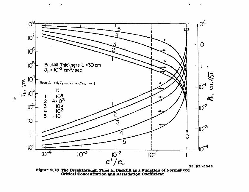
In Fig. 2.16 ft is plotted as a function of the dimensionless interface concentration c'/c, with the retardation coefficient K as the parameter. D is fixed in these computations at 10~5 cm2/*- As c*/c, —• l,h —• 0, because the saturated region becomes very narrow. In this case there is almost no unsaturated region in the backfill and hence the interface position will move very rapidly towards infinity. Five different A' values are shown in Figure 2.16 which shows that for an increasing K the interface position moves more slowly, since a large A implies strong retardation and hence a slowdown of the approach to saturation in the backfill.
The interface position Q(t) is an indicator of the backfill performance because it shows how quickly saturation takes place with a resulting loss of nuclide retardation. If the backfill thickness is b then retardation by the backfill disappears when the saturation interface penetrates a distance equal to b. The breakthrough time 7i for such penetration is given by
71 = (J) (2-6.16) Figure 2.16 also shows the breakthrough time as a function of c'/c, with the same parameter K. The backfill thickness is taken to be 30 cm. Because 7» is inversely proportional to ft2, as c'/c, decreases, 7» decreases. As A' increases, 71 increases also. The importance of saturation in the backfill can be seen by comparing these results with those in which saturation is assumed absent. Assuming a linear isotherm with slope K = 4000, and for the diffusion coefficient D = 10"5 cm2/*, Nowak [1979] showed that it would take 1000 years to raise the concentration at x = 30 cm to 1% of c,. However, if saturation can occur, with c* = 0.01c,, the breakthrough time is reduced to 60 years as seen in Figure 2.16, i.e. only 6 percent of the breakthrough time in absence of saturation.
To apply the solution for semi-infinite geometry to a backfill of finite thickness, one can use the region of Figure 2.16 that spans a concentration ratio c'/c, = 0.1 at the backfill/rock interface. Because 7i is less than 2000 years for h < 104 and c*/c, < 0.1, species with half lives greater than 5000 years can be treated as nondecaying for this analysis.
32
10*
10
n lo-'e
^
10"
10 .-3
10 .-4
XBL83I-504S Figure 2.16 The Breakthrough Time in Backfill as a Function of Normalized
Critical Concentration and Retardation Coefficient

Nsax-Hald Mae* Tjruwfer
The purpose of this analysis is to illustrate the effect of nonlinear sorption on mass transport and to point out that the results can be quite different from results when a constant distribution coefficiert can be assumed. A similar approach can be taken if an actual nonlinear sorption isotherm is known.
2.7 Effect of a Stationary Precipitation Front on Dissolution and Transport
In this section we deal with a single coi.caminant species and analyze the effect of a preci, itation front caused by a discontinuity in the solubility of the contaminant at some distance from the waste package [Light el at. 1988]. The precipitation front may b? due to local geochemical changes such as changes in temperature, pH or redox potential, caused by nearby geologic features or the waste itself.
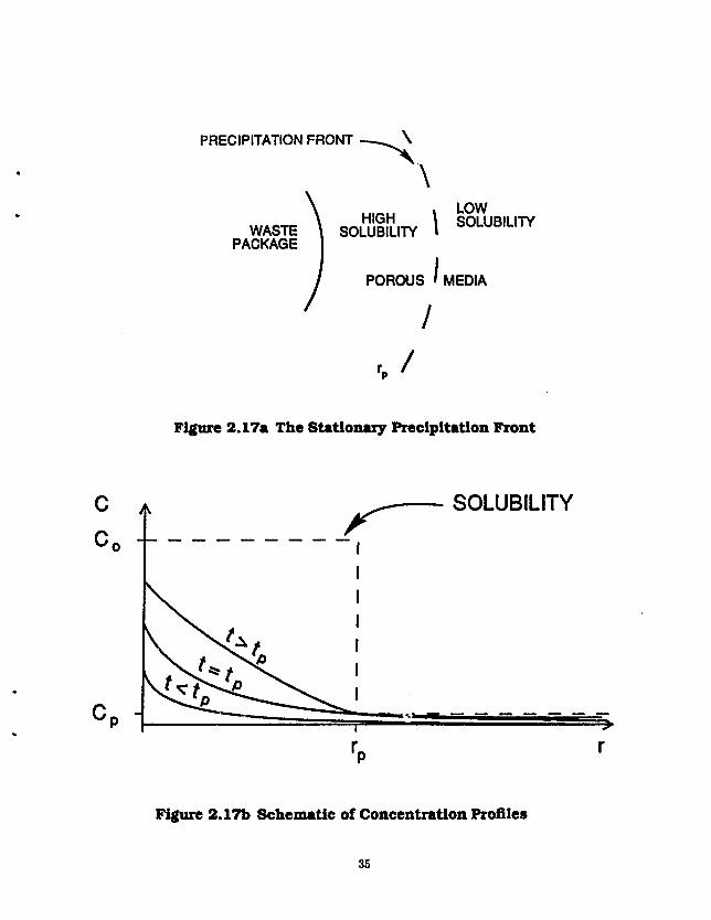
A spherical wpste solid of radius R is embedded in an infinite water-saturated porous medium. There is no contaminant in the porous medium when dissolution begins at time t = 0 and direct contact is assumed between the waste and the porous medium (no container or other barrie s;. The solubility discontinuity, or so-called preiipi'ation front, is assumed to be a concentric spherical shell of radius Rp surrounding the waste package (Figure 2.17a). The iissolution rate at the waste surface is governed by a solid-liquid reaction-rate law with the maximum rate securing when there is no contaminant in the pore water and the minimum rate, zero, approached only as the contaminant concentration in the pore water approaches the solubility at the waste surface. In the limit that the reaction rate goes to infinity, this law reduces to a con'itant-concentration boundary condition.
Transport in *.he porous medium is by fluid-phase diffusion only, with no advection. Retardation of the contaminant in the porous medium is treated by equilibrium sorption.
The precipitation front is assumed to be at a known, fixed location. Inside the spherical front and near the waste package, the solubility c, of the contaminant is high. Outside the front and further away from the waste, the reduced solubility c r is lower. This creates the possibility that some of ihe contaminant being released from the waste will precipitate at the front and beconv inmobilized At early times, when the concentration is below the solubility limits at the front location, the front is transparent to the transport process. The domain from the waste surface to infinity is then treated as a single homogeneous region and we have
-dT-KVci' o<t<tp
(2-7A)
where ci(r,t) is the fluid-phase contaminant concentration for 0 < t < tp, D is the contaminant diffusion coefficient in the pore fluid, and tp is the time at which the solubility limit is reached and precipitation begins. The initial concentration and the concentration at infinity are both assumed to be zero
ci(r,0) = 0, r „ < r < oo (2.7.2)
ci(oo,<) = 0, 0 < t < tp (2.7.3)
The assumed reaction-rate controlled dissolution rate at the waste surface as a function of concentration is
,#ci ~iD3r = Jo(l-~)\ , 0<<<<p (2.7.4)
where j 0 is the forward dissolution reaction rate (assumed constant). To determine the precipitation time, tp, we first solve eq. (2.7.1)-(2.7.4). The contaminant concentration predicted by eq. (2.7.1)-(2.7.4) increases steadily with time and monotonically decreases with distance from the waste. The concentration may not
34
PRECIPITATION FRONT ^ \
WASTE \ SOLUBILITY PACKAGE
\
HIGH \ SOLUBILITY LUBILITY 1
I POROUS ' MEDIA
/
Figure 2.17a The Stationary Precipitation Front
SOLUBILITY
Figure 2.17b Schematic of Concentration Profiles
35

Naur-Bald Maas Uranafar
reach the solubility limit anywhere, but if it does it will occur first at the front location, rp, and we can then determine tp implicitly from the equation
ci(r„,tf) = c r (2.7.5)
At time t = tp, when precipitation begins, the governing equation (2.7.1) is no longer valid at the front so we divide the domain into two regions, one inside the front and the other outside the front. For the inner region
l T = 7 f V c 4 ' <„<t<oo ( 2 J 6 )
where c+fat) is the contaminant concentration for R < r < rp and tp < t < oo. The initial condition for this problem is given by C| evaluated at t = tp
o,(r, tp) = a(r,tp), R<r<rp (2.7.7)
The boundary condition at the waste surface is the reaction-rate law as before with c« replacing c\
~iD8r (2.7.8) rsfl \ c « / lr=H
At the new boundary, r = rp, we set the concentration to the reduced solubility limit cr
Ci(rp,t) = cr, tp<t <oo (2.7.9)
This is a result of the physical requirement that the concentration be continuous across the front and that we are (somewhat artificially) limiting the concentration to the c r limit in the region rp < r < oo. In reality, the front would extend over some non-xero transition thickness without well-defined boundaries. We assume instead an abrupt discontinuity and also neglect the effect which the accumulating precipitate might have on the transport process such as by filling the pores or by moving as a colloid.
The region outside the precipitation front it treated similarly with the governing equation given by
and the side conditions
cs(r,ip) = a(r,tp), rp<r < oo (2.7.11) es(rp,t) = cr, tp<t <oo (2.7.12) cs(oo, 0 = 0, tp < t < oo (2.7.13)
The solution to eq. (2.7.1)-(2.7.4) is
with these dimensionless parameters tr = 1 + 1/a, cr = j0R/tDe„ p = r/R, r = tD/KR1. Using this result, eq. (2.7.5) is solved implicitly to obtain a numerical value for rp = tpD/KR2. Assuming a known value for rp, which is dependent on a and c,/c r, eq. (2.7.6)-(2.7.9) are solved by the Fourier method with the result in infinite-series form
[ b 1 °° P P n=l
A„(r-1>) ,1<P<P" (2.7.15) r c < r < oo v '
36
Naur-Held Ma« Ikamfar
where
_ gppCr/c, <rpp-l
b_ p p ( l - c r / c , ) trpf-\
The series coefficients A„ are given by
4" " ||*r,||2 J *" where
l!*n|| J = /*£(/>) <*P i
the cigenfunctions • „ are defined
*„(p) = sin \\/K{pp - p)], Kp<PP
and the eigenvalues An are determined implicitly from
tan[vA:(^- l ) ]=^
Equations (2.7.10)-(2.7.13) are solved by Green's-function method to yield the solution
C5(/J, r ) . P L C T + _ y r , C l ( „ , r p ) _ P p C r ) ^ _ J — ^ T ( r _ ^ — S - L j «*,, J ; < ; < ^ (2.7.16)
The mass-transfer rate M, representing the flow rate of contaminant species through a concentric sphere of radius r at time t, is proportional to the concentration gradient, in this case
M(r,t) --Airr^D^- (2.7.17) or
where ci(r,(), C4(r,<), or c$(r,t) is inserted for c(r,t) depending on the place and time of interest.
Figure 2.18 summarizes the principal results of the numerical illustration. The normalized mass-transfer rates at two locations are plotted against dimensioniess time, with the location of the precipitation front as a parameter. The mass-transfer rate M {M/t] is normalized by the constant 4irtRDc0 [M/t]. The dimensioniess time r is obtained by dividing actual time by KR?/D [t]. As indicated on the caption for Figure 2.18, the solubility cT in the outer region is set at 10~ 3 of the solubility of the inner, higher-solubility region. The calculations have been done for »=500, to ensure that dissolution is controlled primarily by diffusion.
The upper set of curves in Figure 2.18 shows the mass-transfer rates at the surface of the waste sphere, R, for four locations of the precipitation front r p . The start of precipitation is indicated by the vertical
37

o Q OH
10%
10%
10'i - » — O 0 & 10
i io-' F= I
w
D 10 '
10 , -3
•Onset of Precipitation
(r-R)/R = 0.01
(rp-R)/R = 0.01
0.1
I l l « M i r | I I I M i l l ] IJ I M I M B j I H | I l l l l t l l l I I l l l l l l l |
10 10 10 10 10~210 10° 101 102
Time, tD/KRJ
Figure 2.18 Dimensionless Mass Transfer Rate Out of a Waste Sphere and the Precipitation Front
38

Near-Bald Ma»« Tr»n»f»r
bars. If the precipitation front is close to the waste surface, precipitation starts soon and steady state is reached in early times. The mass-transfer rate at steady-state is about 100 times higher for the precipitation front at (r p — R)/11=0.01 than for the precipitation front at infinity. The precipitation front is essentially an additional sink for dissolving contaminants, and putting it closer to the waste surface magnifies its effect by increasing the concentration gradient at the waste surface.
The lower set of curves shows the mass-transfer rates at the location of the precipitation front. The contaminant takes some time to arrive at this location. When concentration rcachs the local solubility precipitation begins. Once precipitation starts, the mass-transfer rate out of the precipitation front decreases dramatically. The location of the precipitation front affects the time when precipitation begins. It also affects the steady-state mass-transfer rate out of the precipitation front, but only slightly.
At early times, the release rate is controlled by the solid-liquid reaction rate represented by the dirncn-sionlcss quantity a. At later times extending to steady state, the release rate depends on the location of the precipitation front and on the solubility ratio c,/cr.
The result of fixing the front concentration at c r is to steepen the concentration gradient on the waste package side of the front and to flatten the gradient in the region outside the front. The rate of contaminant transport from the waste to the front location is thereby maintained at a higher than normal rate while the rate of transport away from the front is held to lower levels. The difference in the transport rates at the front is the rate of precipitation. Nearly all of the species released at cr from the waste form is immobilized. Whether this scenario is more or less desirable than other predictions without precipitation depends on the goals — whether we care about the waste dissolution rate or far-field transport rates, and whether the assumed uniform solubility is nearer to c, or c r .
If a near-field region of high solubility is viewed as a perturbation to the normal low solubility case, then we may conclude that the effect of the perturbation is to increase the release rate at the waste surface as well as at the precipitation front. The release rate at the waste surface may be greatly affected if the front is very close to the waste surface and the ratio c,/cr is very large. The release rate from the front location will increase with increasing radius of the high-solubility region due to the larger surface area at which the concentration c r is maintained.
The effect at the waste surface has the greatest potential for dramatic influence [Garisto 1986; Garisto and Garisto 1986a,b; 1988; Garisto et al. 1986]. If we apply our model to a controlling matrix species, the dissolution of which releases other waste components, we see that if these components are not solubility limited, their release toward the far-field could be greatly accelerated by a local high-solubility region for the controlling matrix species.
2.8 Isctopic Effects on Solubility-limited Dissolution
In the previous theoretical analyses, solubility-limited mass transfer from waste solids applies if a species in liquid at the waste surface is at constant concentration given by the elemental solubility. However, if there are other isotopes present, the species concentration must be less than the solubility. For an clement with isotopes that decay appreciably during the time of interest, a solubility boundary condition results in a time-dependent boundary concentration of each isotope.
Let there be M isotopes of the element, and 7,- the respective isotopic fraction in the waste solid so that 5^,_j ii = 1. Because the M isotopes decay at different rates, 7,- = fi{t). However, for simplicity we
39

Naar-fMd Maw Tr»n»f«r
assume that [U.S. Department of Energy 1986; Yung ct al. 1987]
7.(0 = 7.'. Vt (2.8.1)
With this assumption, the fractional release rate /(*) for an isotope of elemental solubility c,t, released from the surface of a waste sphere of radius R by diffusive mass transfer into surrounding saturated porous rock of porosity e, based on the initial inventory Mf, is
Mt)=^f^ {i+v^F«^ + JW^j • * > ° ( 2 8 2 )
Eq. (2.8.2) is a suitable approximation for most radionuclides important in high-level waste. It can be used conservatively for species that decay in the time of interest by adopting 7< as the maximum value for that isotope during the interval.
A more accurate approach is to solve the mass-transfer equations for time-dependent fi(t). For an element with two isotopes, the time-dependent Inventories Mi(t) and M,(t) for the radioactive and stable isotopes in the waste solid are [Isayama et al. 1969]
dMi dt
and
^ l = _ A , A f l ( < ) - 4 ^ 2 ( - € £ > ^ ^ ) V <>0 (2.8.3)
dJm=.i^(ceD^my < > 0 (MA)
where c(r, t) is the nuclide concentration in pore liquid. For short-half-life nuclides the assumption can be made that
4*tf ( - t P ^ - W ' A < X i M i { t ) (2.8.5)
and there is considerable simplification of the system of equations to be solved. (2.8.3) reduces to
dMjjt) dt = -A (A/,(<), * > 0 (2.8.3')
and (2.8.4) to
and the fractional release rate is
^ 1 = 0, « > 0 (2.8.4')
J_
V D 0 F y o (M/e-^'-i ' + M/) 2 /
40

N*ar-fl*Id Mu> Tramfar
Table 2.1. Data used for Iaotopic Effect Illustration
Property Units ^Sr 9 0Sr Ref.
Decay Constant (A) per year 0 0.024 Browne and Firestone 1986
Isotopic fraction (7) 0.4 0.6 Browne and Firestone 1986
Initial Inventory (M°) g/MTHM 349 519 Roddy et al. 1986
Retardation Coefficient (A') 200 Pigford et al. 1983
Dilfusion Coefficient (D) m'/a 3 xlO" 3 Pigford et al. 1983
Elemental Solubility (c, e) g/m 3 0.01 Pigford ct al. 1983
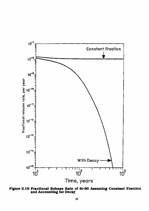
To illustrate, we consider the release of solubility-limited strontium, consisting of radioactive 9 0Sr atid stable M Sr, from spent fuel waste surrounded by porous rock. An equivalent-sphere radius of 1 m is assumed. The waste container and fuel cladding are assumed not to be present, and the waste is assumed to contact ground water shortly after emplacement. Using assumed properties listed in Table I, calculated fractional release rates of 9 0Sr for constant and time-dependent boundary concentrations are shown in Figure 2.19. Because ^Sr is the only decaying species, the fractional release rate considering decay is much less than the more conservative value that neglects decay. Fractional release rates based on the 1000-year inventory, as required by federal regulations, can be obtained by multiplying the values in Figure 2.19 by e 1 0 0 0 \
3 . 0 SOLUBLE SPECIES
In a spent-fuel waste package the soluble cesium and iodine accumulated in fuel-cladding gaps, voids, and grain boundaries of spent fuel rods are expected to dissolve rapidly when groundwater penetrates the fuel cladding [Garisto et al. 1989]. Even though dissolution may be rapid, the rate of release of these readily soluble species from the waste package will be limited by the rate of mass transfer of the dissolved species into the surrounding porous media. Chambre has developed the analytic solution for the fractional release rate of a soluble radioactive species, assuming instantaneous dissolution of the soluble species into a volume V of ground water that has penetrated in the waste package voids at f = 0, and assuming that the groundwater flow rate is small enough that mass-transfer into surrounding porous rock is controlled by molecular diffusion.
3.1 Mass Transfer from Watte Into Porous Rock
We assume that the surrounding porous rock is in direct contact with the well-mixed void liquid (Figure 3.1a), that contains initially a specified quantity of these readily soluble species. Linear geometry is used in analyzing the dissolution of readily soluble species. The species migrate into the porous material under a concentration gradient. Assuming that advective transport in the near-field is small compared with diffusive transport, the space-time-dependent concentration c(x, t) in pore water is given by
t,dc{x,i) _ „a»c(*,l) dt = £>- dz*
-M<c(x,t), x>a, <>0
The initial and boundary conditions are
c(i,0) = 0, x>a
c(a,t) = c'(t), t>0
(3.1.1)
(3.1.2)
(3.1.3)
41
10 .-7
Constant Fraction
1 1—i—i i i i i
Time, years Figure 2.19 Fractional Release Rate of Sr-90 Assuming Constant Fraction
and Accounting for Decay 42
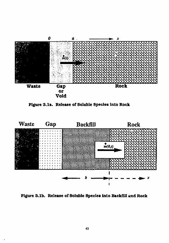
Figure 3.1a. Release of Soluble Species into Rock
Waste Gap Backfill Rock • J ft"ft" ft?ftf'Jftfftfftpft? 'Jft"*.* ft? ft? ft? ft" * J' ft?'*',? ft'ft'ftfft? ft*<?<? ft»» .' ft* ft?ft*ft>V "J >
^ ^ g g S M i g ^
ft?ft?ft! ' j ft? ft? ft* ft? ft?/?/? /?/?/?/? /?ft?ft?» • •V ft* ft" ft" ft1 ft1/? ft? ft?/?/?/?/?/? /? ft?/?/! 'J
V/?/.»/f/*/?/?/? ft*/? ft*/.*/..1 ft* ft? ft'/? •?*•? ft
I
Figure 3.1b. Release of Soluble Species into Backfill and Rock
43

NMr-flald Man IVanafw
c(oo,i) = 0, * > 0 (3.1.4)
where a is the thickness of the "gap" filled with void water. Here c'(f) is the time-dependent well-mixed concentration of the soluble species in the water in the void. To solve for c'(t), the mass balance in the void is
V^jp- = m}(t)-m(t)-\Vc'(t), t>0 (3.1.5)
where mj(t) is the rate of dissolution of the species from the waste matrix into the void volume V, and m(t) is the rate of species migration into the rock. To solve Eq. (3.1.5), we use the initial condition
c'(0) = c" (3.1.6)
where c° is the concentration of the species in the void water, resulting fro,;, the assumed instantaneous dissolution of the readily soluble form of the species. Chambre has obtained the solution to Eq. (3,1.5)
JO
where
•'(I) = c»e-A ,F(0 JO + ^fm,(t- r)e-*TF(/JJr)rfr, t > 0 (3.1.7)
F(/?s«) = ^'aky/jPi (3.1.8)
and 0 = y/DKt*/a*
The rate of mass transfer of the species into the rock is
m(0 = - S £ > £ ^ H , t > 0 (3.1.9) ox
where S is the surface area of the interface between the void space and the rock (5 = V/a). Using (3.1.6) the solution to (3.1.7) is
m(t) = c V V e - * ' { - L - 0F(j8»()} + 0 J' m,(t - r ) e - * r { - ^ = - /?F(0sr)}dr, t > 0 (3.1.10)
To obtain an expression for rhj use (2.1.2.2.1) to estimate a dissolution rate of the controller species, and the congruent dissolution assumption to get the species' matrix dissolution rate. The matrix of nuclear waste is likely to be either UO2 in spent fuel or silica in glass waste. The matrix species have low decay rates, thus the assumption of a stable species is justified. In the planar geometry used in this section, we let R —» 00 to obtain
m { = Sc.tJ^- (3.1.11)
where mc is the mass transfer rate of the controller or don* ,nt species. Using the congruent dissolution assumption
where M(t) is the species inventory at t and Mc(t) is the controller's inventory at t we obtain
44
NMr-fl*ld Mui IVuufu-
whers M" is the initial inventory of the species in the waste package, and M" is the initial inventory of the controller species in the waste package. We have the final results
c(x,t) = c ' e - ^ ' V ^ W ' - V ^ e r f c Lyft+ N / * ^ ~ a ) \ + c , ^ x / ^ 7 K ^ F ( ^ 2 0 e - x ' , * > 0
(3.1.14) and
th(() = JpVe-u {-== - „•: , / t t )} + p£ e"*' | ~ - /JF(/9"r)} dr (3.1.15)
from which the fractional release rate can be calculated [Kim, Chambre and Pigford 1986].
A computer program, UCB-NE-107 [Lee 1989b] implements eq. (3.1.15) and is available from the National Energy Software Center.
Figure 3.2 shows the fractional release rates of l 3 5 Cs, 1 3 7 Cs and 1 2 9 I based on Eq. (3.1.10). In this illustration we consider the release from a bare waste form exposed to ground water shortly after emplacement, conservatively neglecting the mass-transfer resistance due to containers and cladding. The lower curves show the solubility-limited dissolution rate from the waste matrix, assuming congruent dissolution and a uranium solubility of 10" 3 g/m 3. A conservatively high diffusion coefficient of 0.12 m 2 /a is used throughout the analysis, and a porosity of 0.01 is assumed. The fractional release rates in Figure 3.2 are normalized to initial inventories. At t = 0, one percent of these species is assumed to dissolve into the water-filled void space of 0.45 m 3 . The calculated USNRC fractional release rate limits on these species, based on initial inventories, are
1 3 5 Cs = 4.5 x 10- 5 per year 1 3 7 Cs = 1.8 x 10" 1 0 per year
1 S 9 I = 5.4 x 10"4 per year
With these parameters, the early contribution from gap inventory is more than 107-fold greater than the contribution from the waste matrix. For early times, the fractional release rates of l 3 5 Cs and 1 3 7 Cs are almost equal, but the 1 3 7 Cs release rate decreases rapidly because of radioactive decay, whereas the release rate of 3 x 10⁶-year 1 3 5 Cs is characteristic of a stable species. Because of the assumed negligible sorption of iodine in the rock, the early fractional release rate of 1.7 x 10⁷-year 1 2 9 I is lower than the rates of strongly sorbing cesium, but the less rapid early depletion of iodine in the void water results in greater fractional release rate of iodine after about 20 years.
The fractional release rate of 1 3 7 Cs exceeds the USNRC release rate limit for several hundred years. The presence of metallic containers, and the time-distributed nature of container failure will likely help meet the requirement.
3.2 Mass Transfer of Soluble Species Into Backfill and Porous Rock
The situation studied and the notation is similar to Section 2.3.1, except that linear geometry of Figure 3.1b is used here. Here we define the origin at the interface of the gap and the backfill. The backfill is of thickness 6, and the surrounding rock is infinitely thick. Water flow is small enough that near-field mass transfer is principally by diffusion.
45

10
10"'N
USNRC LIMIT 1-129 5.5e-4 Cs-137 1.7e-10 Cs-135 5.0e-5
Cs-135 from matrix
*T i 11imi| r IIIIIIII -i IIIIIIII i IIHIIII i IIIIIIII TI I I I I I I I I I1IHII|
10° 101 102 10 104 105 106 107
Time, years Figure 3.2 Fractional Release Rates of Some Soluble Species
46

Nwur-flald MM* Ikamfer
The governing equations are
1 ^ , 0 - A d , _ 6 < x < 0 ) t > 0 , Z J l S ^ (3.2.1)
W = D ^ ~ X c i ' x>0.t>0,D2 = ?gl (3.2.2)
The side conditions are
c,(x,0) = 0, - i < i < 0 , (3.2,3) c2(*,0) = 0, x > 0 (3.2.4) c,(0,<) = C3(0,<), <>0 (3.2.5)
- « i D / » i ^ « - ' s ^ < , » ^ »t * = 0 , t > 0 (3.2.6)
csfoo.O^O, <>0 (3.2.7)
We assume that the readily soluble spechs are readily at t = 0 into water that has filled the waste-package void volume V which has a surface area S. Here we do not include the slower release of the same species from the waste matrix. The mass balance of the readily soluble species in the void volume is
The initial concentration of the readily soluble species is taken to be
C l ( -6 ,0) = c° (3.2.9)
We will write the solution in terms of the rate of mass transfer across the backfill/rock interface
m(0, () = 2 K 1 e 1 c » S ^ y £ UEexF [t*L+l£*L J _ u D l e x p { ( 2 „ + ijfc, + DlwH)
where
Numerical Illustrations
* = v S s »-*'««^ «"•»> Figure 3.3 shows some example fractional release rates of 1 3 5 Cs, l 3 7 Cs and 1 2 9 I based on (3.2.10)
[Chambre ei al. 1986], In this illustra ion we consider the release from a bare waste form exposed to ground water shortly after emplacement We assume that fuel cladding and a container are not present, water contacts the interior of spent-fuel rods shortly after emplacement, and 1 percent of the total inventory of cesium and iodine is rapidly dissolved into the "void water" that fills voids in the waste package. The void water is equivalent in volume to a 7.4-cm thick layer of water between the waste solid and backfill. Ground-water flow is assumed to be small enough that mass transfer through backfill and into the rock is controlled by molecular diffusion. Time-dependent fractional release rates at the backfill/rock interface,
47

m"3^ 1-129 10 2
1-129
1-129
io- 4i 1-129 Cs-135
.> 10 =
1-129
t— -
£ -0~ / Cs-135 CO
2 10 S E o =
' i io"7= CD
<¥-> CO 1— CD
co r CO i— CO
° a" JD S 10'% 1 Cs-137 CD CD = <D = »— J
— -.-.-9 g 1 0 i .2 z
"•P ~ it 1 0 1
Cs-137 .2 z
"•P ~ it 1 0 1
10"!
•irf 1 2 I |
10 i M i I I imi| 111 mil 111 Mini
10"2 10"1 10° 101 itf 103 104 106 10° 107
Time, years Figure 3.3 Fractional Release Rates of Some Soluble Species Through 30
cm of Backfill 48

N«ar4Md MM* IVuMfor
normalized to initial inventories, are shown in Figure 3.3 for a diffusion coefficient of 10"5 cm2/s, backfill porosity of 0.2, rock porosity of 0.01, a concentration-based distribution coefficient of 100 for cesium, and for a backfill thickness of 30 cm. Nonsorbing I 2 9 l arrives at the backfill/rock interface in less than a year, with a petk release rate about tenfold less than the equivalent fractional release rate limit calculated from the NRC criterion [USNRC 1983]. 1 3 S Cs and 1 3 7 Cs arrive later simultaneously, but the normalized peak release rate of 1 3 7 Cs is less because of more rapid decay. The peak release rate of I 3 5 Cs is about tenfold less than its release rate iindt, but the peak release rate of cesium-137 exceeds its limit by several orders of magnitude for several hundred years.
A computer program, UCB-NE-108 [Kang and Lee 1989] implements eq. (3.2.10) and is available from the National Energy Software Center.
3.3 Temperature Effects Calculation of the effect of repository heating on the rate of diffusive mass transfer of soluble species
into the rock is simpler because the only parameter affected by temperature is the diffusion coefficient, if the retardation coefficient can be assumed constant. Chambre obtained the solution of equation system (3.1.1) through (3.1.5) for a constant diffusion coefficient [Section 2.5], and Kim modified the solution for application to the problem with a time-dependent diffusion coefficient [Kim et al. 1988], adapting the transformations given in Chambre et al. [1985].
The solution gives the species concentration in the void as
c{t) = c 0
e - A , exp{ /? 2 J g{t')dt'\ettiJp j g(t')dt\ t > 0 (3.3.1)
where
The concentration of the species in the rock is
e(x,t) = c ,
e - A , e*'<*->/ a exp{/J : ! / g(t')dl'}
xerfclj/J' / ' , ( ( ' ) * ' + M £ z £ l _ _ _ i _ _ _ I * > a , « > 0 (3.3.2) IV Jo 2« y/FfolWWJ
The mass flux of the species into the rock is
m(t) = -SD{t)t?4g&, t > 0 (3.3.3) ox
Using (3.3.2) the solution to (3.3.3) is
rh(t) = cVVfl(t)e"A'| l -/?e g'/.' ( l' )'"'erfctA9' /'g(t')dt> \,t> 0 (3.3.4) l ^ Jo »(<')*' V J ° J
The results are illustrated for 1 3 5 Cs in Figures 3.4 and 3.5. For the time intervals of Figure 3.4, the 1 3 5 Cs concentration in the water filling the waste package is always lower than that predicted on the basis of
49

1 0 *
ro 4 101
O)
c o
-t— 10°
p iu. - t—
c
nee 10"'
o o CL D 10'2
o
10 -3
K = 1000 D = 7.19x10"2 m 2/a
i iiiiiijj 11 mini i niiiiij 111IIIIII
10" 10' 102 105 104
Time, years
1 1 1 I I I I I I
10 5 106
Figure 3.4 Time-Temperature-Dependent Concentration of Cs-135 in the Void
50

CO CH
H r i
•s «» 0
ft 9 a tt o ft E » s » » o CO 0 1
Fractional Release Rate, a - 1
i
OM
— # °°: 3 — CD > =
« • < Q L -CD -Q _ - \ «. — w o M
J
°̂

NMT-JMd Maa* Transfw
a constant ambient temperature. At very early times, as shown in Figure 3.5, the higher diffusion coefficient causes greater mass transfer rate from the waste-package water into the surrounding rock, depleting the concentration in the waste-package water. This early depletion results in a later mass-transfer rate that is lower than would occur if the temperature were always at the ambient temperature. Thus, for most times of interest, the release rate predicted by using a diffusion coefficient evaluated at ambient temperature is conservatively higher than the release rates corrected for repository heating.
4.0 DISCUSSION OF THEORY AND LIMITATIONS
4.1 Effect of a Liquid-Filled Annulus Between Waste and Rock
The mass-transfer equations described above assume that the waste solid is in contact with porous rock containing ground water. The assumption of a constant solubility-limit boundary concentration for tow-solubility species has been discussed above. The theory assumes conservatively that the corrosion-resistant container of the waste package has failed and that its corrosion products offer no resistance to mass transfer. If there is a liquid-filled annulus between the waste package and the rock, or between the waste solid and the rock, the mass-transfer equations are still applicable, provided there is no appreciable convective flow through the annulus. It is reasonable to assume that the liquid between the waste solid and rock is well mixed, so the dimensions of the borehole should be used for the geometrical parameters in the mass-transfer equations. The effects of convective transport in the annulus and convective flow through the waste solid have not been analyzed, in the present report.
4.2 Effect of Flow Direction and Geometry
The analyses described above have assumed that ground water flows normal to the cylindrical axis of a wiste package. Other flow directions are possible in a repository. Chambre has considered flow parallel to the axis, as well as other waste-form geometries, and has shown that predicted dissolution rates are not significantly different.
4.3 Hjrdrodjmamic Diaperalon
It has been suggested by some [Ross 19B7] that because of hydrodynamic dispersion the effective diffusion coefficient that appears in the analytical solutions should be a value greater than that for molecular diffusion. However, experimental data [Sherwood, Pigford and Wilke 1975; Pfankuch 1963] for effective diffusion coefficients in packed columns, show that for the ground water velocities and dimensions typical for individual waste packages the value for molecular diffusion should be used. At locations far enough removed from the waste surface for hydrodynamic dispersion to become important, the concentration gradients are too small to affect the mass transfer from the waste surface. However, if the same governing equations were to be applied to mass transfer over greater distances, the effect of hydrodynamic dispersion should be considered. As Pfannkuch [1963] shows, the effective diffusion coefficient will increase with distance, requiring equations for diffusive-advective transport with a space-dependent diffusion coefficient, such as that developed by Chambre [Kang, Chambre and Pigford 1985].
4.4 Effect of Radioactive Decay
The equations described above were developed for radionuclides with no radioactive-decay precursors.
52

Naur-Bald Mm— Tranafar
Some of the radionuclides important in repository performance assessment are continuously generated by decay of precursors, e.g., Ra-226 from U-234 and Th-230, and Th-229/Ra-229 from Np-237 and U-233. It is not necessarily conservative to apply the mass-transfer equations for a species with no precursor separately to each member of the decay chain, assuming that each species is at its solubility limit in ground water near the waste surface [USDOE 1986]. Decay of a precursor in the transport field can cause penetration of its daughters into the field further from the waste surface, resulting in greater rates of mass-transfer into the rock. This is particularly important when mass-transfer theory is used to predict the rate of transport through backfill, or through other intervening diffusing media, into surrounding rock. The greater penetration of a long-lived precursor through the backfill is a means for a shorter-lived daughter to appear at appreciable distances from the waste surface. A near-field mass-transfer analysis applicable to the simultaneous diffusive transport of a radionuclide chain has been developed and is described later.
4.5 Local Sorption Equilibrium
These equations assume local sorption equilibrium, with an assumed constant retardation coefficient. Mass transport without local chemical equilibrium between liquid and solid phases has been analyzed in a previous report [Zavoshy et al. 1985]. Mass transfer with local sorption equilibrium but with a concentration-dependent sorption distribution coefficient is discussed in Section 2.6 of this report.
4.6 Surface Diffusion
The analyses and equations above assume no diffusion of sorbed species on or in the solid phase. However, some experiments with selected species and solids have demonstrated appreciable surface diffusion of sorbed species. For accurate predictions of mass transfer an experimentally determined diffusion coefficient is desirable, rather than using the upper-limit value usually adopted in our numerical illustrations. In making such measurements, it is important to check also the possibility of surface diffusion. The mass-transfer equations can be reformulated if such measurements indicate that surface diffusion need be considered.
4.7 Interference from Other mute Packages
These equations for the rate of mass transfer from individual waste packages conservatively neglect the overlapping concentration fields resulting from species dissolved from nearby waste packages. For high-level waste packages separated by several meters the concentration fields are not expected to overlap enough in the near field to significantly reduce the mass transfer from an individual package.
Although nearby waste packages do not appreciably affect the dissolution and release rates, the overlapping concentration fields do affect the calculation of far-field transport from arrays of waste packages [Pigford tt al. 1980; Kim et al. 1987; Ahn et al. 1987]. Array effects are illustrated in Figure 4.1, where the local steady-state concentration of a contaminant along the flow path, normalized to the steady-state concentration at that position for an infinite plane source of the same areal source strength, is plotted against a dimensionless quantity that increases with distance along the flow path. Near the waste package the three-dimensional contaminant plumes from irradiated packages must be considered. At greater distances the concentration fields from individual packages mer^e, the concentration is reduced by transverse dispersion from the outer edges of the coalesced plumes, and the concentration field is characteristic of that from a single finite planar source of the same areal source strength as the array.
53
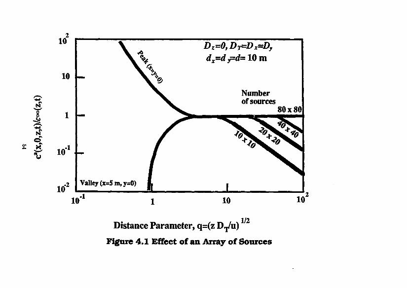
10 y6
Dz =0fD^=Dx^Dy
10 m m
y6 dx
=dy=d= 10 m
1
X Number of sources
80x80
10 1
TO' 2 Valley (x: =5m »y=0) i 1
10" 10 10
1/2 Distance Parameter, q=(z Drj/ii) Figure 4.1 Effect of an Array of Sources

N*ar-fl«ld Man Tr»n«f«r
4.8 Porous or Fractured Rock
The mass-transfer equations described above, and extensions of these equations described in some of the following sections, assume that the surrounding the waste solid can be reasonably characterized as a porous solid. A steady-state equation for mass transfer into ground water in discrete fractures has been derived from boundary-layer theory by Neretnieks [1978]. Chambre's analytical equations for time-dependent mass transfer from a waste solid through porous backfill and into discrete fractures have been discussed above.
4.9 Constant Temperature
The equations described above assume that the waste solid and surrounding rock arc at a constant and spatially uniform temperature. Extensions to account for time-dependent temperatures expected if the waste solid is exposed to ground water when the repository is heated by radioactive decay have been described in Sections 2.5 and 3.3.
4.10 Constant and Uniform Chemical EnYironment
In predicting the dissolution rate of low-solubility species, it is important to examine the possibility of solubility changing with time, due to changes in the local chemical environment. For example, dissolution of borosilicate glass waste causes local changes in pH, thereby affecting solubility of several species. Also, the oxidizing environment due to air during construction and waste emplacement can revert to a more reducing environment after repository sealing and, for saturated-rock repositories, after resaturation. As a result, the solubility of species with several oxidation states, such as uranium, neptunium, and other actinides, can decrease with time. If the chemical environment stabilizes within a few hundred years, while the protective container is still effective, the solubility corresponding to the stabilized environment would be the appropriate value to use in predicting release rates.
A longer-term mechanism for changing the chemical environment is the radiolysis of ground water by alpha particles from transuranics in the dissolving waste. If radiolytically produced hydrogen can escape, hydrogen peroxide can create a locally oxidizing environment and greater solubilities. Radiolysis can be particularly important in affecting the long-term release from spent fuel, because there uranium is the matrix and because of the greater quantity of alpha emitters than usually found in borosilicate glass waste. Andersson, Rasmuson and Neretnieks [1982] have analyzed the progress of such a redox front for a spent-fuel repository in granite, determined by the rate of peroxide generation, mass transfer of peroxide from the waste surface, and reaction of peroxide with ferrous compounds in the water and rock. The result is a moving and expanding redox front, a transition from the oxidizing region of high uranium solubility near the waste surface to the low- solubility reducing region. To predict the net rate of release of uranium across this front, the equations for mass-transfer of low-solubility species can be applied, using the radius of the redox front as the geometrical parameter.
4.11 Release of Other Species From a Low-Solubllitjr Waste Matrix
If there is no preferential leaching of other chemical elements contained in the low-solubility waste matrix, all constituents in the matrix can be released congruently as the matrix dissolves or restructures. Upon release from the matrix, a constituent can all dissolve and transport into the surrounding media, or it can form a local precipitate and dissolve at a rate controlled by the precipitate solubility.
55

N*ar-fi«ld MSM TV»n«f«r
Restructuring, also referred to as alteration, is the reaction of the waste solid with water or with oxidizing constituents in the water to form a solid of different lattice structure, thereby exposing other constituents in the original matrix to reaction with water. The restructuring process may involve local dissolving of the matrix and precipitation of a new solid phase of the matrix components. In the present report this will be referred to as alteration. Dissolution here refers to net dissolution, so that the released species remains locally in solution and undergoes dilfusive-convective transport through ground water in the surrounding media.
For example, the rate of dissolution of uranium from spent fuel can be predicted by mass-transfer analyses of solubility-limited transport of uranium through the surrounding media. The appropriate solubility is that of the stable solid phase of uranium in the local chemical environment at the waste surface. Assuming that dissolution of the uranium is the rate-limiting process for other constituents in the spent fuel, the rate of congruent dissolution of another constituent can be calculated by specifying that the instantaneous fractional dissolution rate of that constituent be identical with instantaneous fractional dissolution rate of the uranium. For rigor, the fractional dissolution rate must be interpreted here as the instantaneous mass rate of dissolution of a species divided by the instantaneous inventory of that species in the waste. Thus, for congruent dissolution the equations for solubility-limited dissolution of a single-component waste solid can be applied to the waste matrix, thereby yielding the fractional dissolution rates of the constituents.
Restructuring alteration of the matrix can also release waste constituents for dissolution or for precipitation. For example, uranium dioxide can be locally oxidized to U3O7 without structural changes. If the local environment is sufficiently oxidizing, non-isomorphous UsOg can form, releasing other matrix constituents to react with ground water. If dissolution of a matrix constituent is not rate limited by any other process, its fractional dissolution rate can be assumed to be congruent with the fractional alteration rate of the uranium matrix. Given experimental data for the fractional alteration rate, the fractional dissolution rate of a constituent can be specified as a boundary condition for mass-transfer analysis.
Also, as has been discussed earlier, a waste constituent released by matrix dissolution or by alteration does not necessarily dissolve. The solubility of that constituent can be sufficiently low that a stable precipitate of that constituent will form at the waste surface. The dissolution rate of that constituent can then be analyzed from the equations for solubility-limited dissolution and mass transfer, using the constituent solubility as a boundary condition.
One can calculate the fractional dissolution rate of a waste constituent for each of these three processes: (a) dissolution congruent with dissolution of the waste matrix, (b) dissolution congruent with matrix alteration, and (c) dissolution at a rate controlled by the elemental solubility of that constituent. The rate-limiting dissolution process will be that with the lowest predicted dissolution rate of the constituent. Radioactive decay within the waste solids can cause the relative inventories of the waste matrix and of another waste constituent to change with time. As a result, the rate-limiting dissolution process for a constituent can change with time. For example, a low-solubility radioactive species initially present in sufficient concentration to be dissolution-rate-limited by its own solubility can eventually decay to a concentration in the waste low enough to be dissolution-rate-limited by matrix dissolution or alteration.
Borosilicate glass waste and its constituents can undergo the release and dissolution mechanisms described above. Silica in the glass matrix can dissolve. Likewise, the amorphous structure of glass can restructure to a thermodynamically stable solid phase.
56
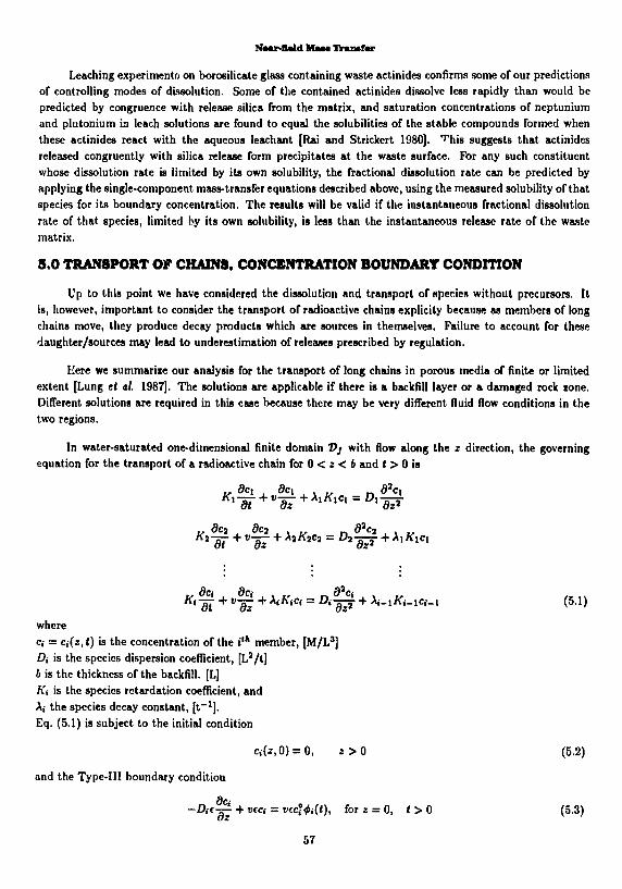
Naur-Bald Maaa IVanafar
Leaching experiment on borosilicate glass containing waste actinides confirms some of our predictions of controlling modes of dissolution. Some of the contained actinides dissolve less rapidly than would be predicted by congruence with release silica from the matrix, and saturation concentrations of neptunium and plutonium in leach solutions are found to equal the solubilities of the stable compounds formed when these actinides react with the aqueous leachant [Rai and Strickert 1980]. T his suggests that actinides released congruently with silica release form precipitates at the waste surface. For any such constituent whose dissolution rate is limited by its own solubility, the fractional dissolution rate can be predicted by applying the single-component mass-transfer equations described above, using the measured solubility of that species for its boundary concentration. The results will be valid if the instantaneous fractional dissolution rate of that species, limited by its own solubility, is less than the instantaneous release rate of the waste matrix.
5.0 TRANSPORT OF CHAINS, CONCENTRATION BOUNDARY CONDITION
Up to this point we have considered the dissolution and transport of species without precursors, It is, however, important to consider the transport of radioactive chains explicily because as members of long chains move, they produce decay products which are sources in themselves. Failure to account for these daughter/sources may lead to underestimation of releases prescribed by regulation.
Here we summarize our analysis for the transport of long chains in porous media of finite or limited extent [Lung et al. 1987]. The solutions are applicable if there is a backfill layer or a damaged rock zone. Different solutions are required in this case because there may be very different fluid flow conditions in the two regions.
In water-saturated one-dimensional finite domain V] with flow along the z direction, the governing equation for the transport of a radioactive chain for 0 < z < b and t > 0 is
where Ci = e,(z,0 is the concentration of the t'* member, [M/L3] Di is the species dispersion coefficient, [L2/t] b is the thickness of the backfill. [L] A'i is the species retardation coefficient, and A,- the species decay constant, [ t - 1 ] . Eq. (5.1) is subject to the initial condition
Ci(*,0) = 0, * > 0 (5.2)
and the Type-Ill boundary condition
dci dz (5.3)
57

where ̂ ,(<) is the source term. A Type-Ill boundary condition specifies both concentration and flux. At the other end of the finite region, the boundary condition is
-Di<j!- + veci = hlci-<i;(t)], for z = b, t > 0 (5.4)
where c* is the average concentration of the nuclide outside of the region and h is an assumed constant mass-transfer coefficient describing the mass flux at z = b. Eq. (5.1) can be re-written as
St + i£ +*«-S + *-«*-»' *>0- *><>.'-».*.••• ("• ) where
„ K{Xi Ki-iXi-i
"• = 0- Vi = -5T' "'-' = — — The general analytic solution for c<(«,() can be expressed as a sum of functions. For example, for the t"1
member of any chain i-J
c,(«,0 = cf >(*,<)+ S^' ) (* ,0 , *><M>0,i=l ,2, . . . (5.5)
If this decomposition is used, then the equation system (5.1) - (5.4) can be written as
Wtdr + Tkdr + "tC' = ^ " + " < - » * - » ' 0 < * < o o , i > 0 , i / , = 0 , < = l , 2 , . . . U < < (5.6)
«#>(«, 0) = 0, z>Q (5.7)
-Dt^'^'V + ««#>(<),<) = StjvcclMt), }<t,t>0 (5.8)
where % is the Kronecker delta that vanishes for / j£ j and is unity for I = j .
-Dte&^+vec¥\b,t) = hlcU\b,t)-6ljeW)], j<t,t>0 (5.9)
We will illustrate the solution for a Bateman boundary condition, at z — 0,
i
«.(o,o=E f l « e " A j ' ( 5 1°) in which the Bateman constant By is
^Ecfxrri^Vn^-A,) (5.11)
where c£, is the initial concentration of the m'h nuclide and the product term in the denominator is defined as unity when m = j = i.
*'>-Maf{x>«-'''£(^)^<'-«-*''' H 58

Naar-flMd MM* Transfer
+ l > E ^ ' £ f ; ( ^ ) r , .*•>*;% (i-e--)},;;0°,^i,2,.... 3 = 1 t=l n=>m=l V ^ m ' / 11; ; ; l 1"'-' ,m+TnrJtin* ) * ^ u
(5.12) where
&ni = §-n{& + &) • & = {jnf + £ ( * . - A*). c«> = fi *«
and the eigenvalues 0m are determined from solving numerically
t a n / ? m 4 = - ^ i (5.13)
Figures 5.1 and 5.2 are illustrations for the S34U-» ! l 30Tli—>MeR,a chain. In these figures the vertical scale is logarithmic to show the very small amounts of the daughter nuclides. Figure 5.1 shows the concentration profile normalized to the initial concentration of the first member at the inner edge of the first layer, as a function of distance at 1000 years. Because initially there is no thorium, all M 0 T h comes from the decay of 2 3 4 U. This figure shows relatively little 2 3 0 Th in the field, because the , 3 0 T h half life is so short relative to that of 2 3 4 U. Similarly, the concentration of 2 2 6 Ra cannot be shown in this figure because its half life is even shorter.
At the time of Figure 5.1, 2 3 4 U has reached its steady state while 2 3 0 Th and 2 S 6 Ra are still rising. 2 2 6 Ra shows a maximum inside the backfill.
Figure 5.2 show flux profiles, at both interfaces of the backfill, normalized to to the initial concentration of the first member at the inner edge of the first layer, as functions of time. In Figure 5,2 the solid curves represent the mass fluxes at z = 0 and the dashed lines the fluxes at z = 6. Also plotted are the mass fluxes of 2 2 6 Ra for high h (the dotted curves) for comparison. For a low h we show only 3 3 4 U and 2 3 0 Th since the 2 2 6 Ra flux is too low to be shown. One can see that after 1000 years the mass fluxes of 2 3 4 U at z = 0 and at z = b are almost equal, which means the backfill can no longer retard the migration of uranium. On the other hand, 2 3 f l Th does not show the same phenomenon, and the backfill still provides some retardation. This is also true for 2 2 6 Ra, though not shown here. The decay effect is illustrated by the thorium flux at ; = 0, which is higher than that of its 23*U parent after one thousand years.
Strong water flow in region 2 can enhance the mass fluxes at the outer surface of backfill, as can be seen from the dotted curves. Note that the mass flux of 2 2 6 Ra at z = 4 is higher than that at z = 0 for both values of h.
A series of computer programs, known as UCB-NE-40,41,51,51,52, implements eq. (5.12) and other similar solutions in Lung [Lung et al. 1987]. These computer programs are available from the National Energy Software Center.
6 .0 NEAR-FIELD MASS TRANSFER IN A SALT REPOSITORY
Salt is the proposed host rock for geologic repositories of nuclear waste in several nations because it is "dry" and probably "impermeable." Although experiments and experience at potential salt sites indicate
59

c
• 4 —
c O c o
10° 4
ICT'J
10"2-d
.-3 O 10 -d 0)
"^ irT 4_l £ 10 =| o
r 5 10 "̂
.-6 10 H
0.00
«"U
D-=3.15X10-*m 2/yr e = 0.3
L *= 0.3 m h = lO - 1 m/yr
K, 120 1500 300 N,° 1 0 0
M 0 T h
-£]
0.05 0.10 0.15 0.20 Distance, m
0.25 0.30
Figure 5.1 Normalized Concentration Profile for U-234—Th-230—Ra-226 in Backfill as Functions of Distance at 1000 years, Bateman-type boundary condition

D = 3.15X10- 2 m 2 /yr L = 0.3 m
h = 10"4 m/yr 2 3 4 u _ f 2 3 0 T h _ ^ 2 2 6 R a
Ki 120 1500 300
N,° 1 0 0 at z = 0
"1 1' ! I I I I l l | 1—I I I llll|—'—I—I I ' l f l lH
10 10' 10" 10* 105
Time, years
i • " f i i i m i 106 10
Figure 5.2 Normalized Blass Fluxes for U-234—Th-230-Ra-226 at both ends of the Backfill as Functions of Time, Bateman-type boundary condition

N»ar-fl«ld Man TV»rif«r
that salt may contain brine, the low porosity and permeability of jalt make ;* dill a good choice for geologic isolation. Here we summarize some analyses of near-field mass transfer in salt repositories [Pigford and Chambre 1985].
6.1 Brine Migration
Brine in grain boundaries of natural salt can flow di>e to pressure differences within the salt. It is paramount to know the magnitude of such flow and its contribution to radionuclide transport.
When salt is mined to create a waste repository, brine from grain boundaries will migrate into the room?, tunnels and boreholes because these cavities are at atmospheric pressure. Heat-emitting waste packages will impose temperature gradients in the surrounding salt. Hot salt near the waste package expands against the waste package and surrounding salt, creating high compressive stresses near the waste package and resulting in pressure above the lithostatic pressure. Brine pressure further increases because grain-boundary brine expands more than does the salt. This increased pressure gradient causes brine to flow outward into the cooler salt. Outward flow of brine relieves the pressure gradient on the fluid, which finally relaxes to near-lithostatic pressure.
The Darcy velocity can be written as kdP
v(r,t) = - - ^ (6.1.1)
where P is the relative pore pressure [M L - 1 t - 2 ] , r is t.ie distance variable [L], k is the permeability [L2], ft is the fluid viscosity [M L - 1 t - 1 ] .
To obtain an expression for ^£, we treat the salt as a linear thermoelastic solid. McTigue [1986] derived the following expression, written here for salt surrounding an assumed spherical waste solid,
where 6(r, t) is the relative temperature, actual minus ambient [T], R is the radius of spherical-equivalent waste package [Lj, and 6', d are constants which are functions of material properties
b' = 4 G B ( 1
9(1-
d^ k2G{l-u) ~ v \-1v
where G is the shear modulus [M L - 1 t~ 2 ] v is Poisson's ratio for the solid phase J>U is the undrained Poisson's re io t is the reference porosity or/ is the fluid-phase thermal expansion coefficient [T _ 1 ] a" is the second cubical thermal expansion coefficient of the solid [T - 1 ] , and
62

Nwfl«ld M M TtuMfar
B is the pore-pressure modulus, where
1 K(l-K,/K'.') B K.j{l-KIK',)
in which AC is the bulk modulus [M L - 1 t~ 2 ] , and the subscripts / and * refer to the fluid phase and solid phase, respectively.
Eq. (6.1.2) states that the variation in pore pressure is due primarily to the change of relative temperature. The major assumptions in the equation are • The system is linearized. • Thermal convection is neglected. • Material properties are constant with temperature. Thus (6.1.2) is only valid for small temperature changes. • The porous material is homogenous.
According to (6.1.2), the pressure Reld response is due primarily to the change of temperature, on the right-hand-side of (6.1.2) so we must obtain an analytic expression for the time derivative of temperature.
Neglecting heating effects from nearby waste packages, and assuming polar and azimuthal symmetry, the governing equation for the temperature profile is
where K is the thermal diflusivity [L2/t]. We use a known thermal decay rate as a boundary condition for solving (6.1.3)
where A is the thermal conductivity [M L t " 3 T - 1 ] , Q, is the initial heat flux of the waste package [M/t3], and f(t) is a known time history of the normalized heat flux of the waste package. The other side conditions are
<?(oo,J) = 0, t>0 (6.1.5)
0(r,O) = O, r>R (6.1.6)
Then the relative temperature at the waste package surface is
•L- Tjf «-" [V=5—{»}-{l/F}] * <"*> where
The temperature profile in the salt is
». = 2 i5 (6.1.8)
e = -"^ P"-4^{'-^}-^{^^h{^*m dr
(6.1.9)
63

NMr-flald Mm Ihuwfar
When given a time-history of heat flux from a waste package, (6.1.8) allows us to obtain the temperature at the waste package surface and the time derivative of (6.1.9) gives us the source term for (6.1.2).
We shall give the analytic solutions for a hot waste package in an emplacement hole backfilled with crushed salt [Hwang et al. 1987; 1989a). Thermomechanical studies have shown that salt creep closes the air gap between the waste package and the rock salt in a matter of months to a few years after the emplacement of the waste package. The governing equation for brine flow is eq. (6.1.2) and the initial condition is
The boundary conditions are
P(r,0) = 0, r>R (6.1.10)
lim P(r,t) = Q <>0 (6.1.11)
We will express the solution as the Darcian brine migration velocity
B ( * ' ° = » R * { C X * ) l l S ( t ~ T m ' T ) d T ( 6 1 l 3 )
where the * function is
+Vx\v - \)
and
expltf - 1) + vjjerfc | | ^ + Vx*J - p'exp {(*; - 1) + X<f>3t} erfc { ^ ^ + P v ^ } ]
(6.1.14)
<p2 = d/K, ( = r/R, x = *!&
For illustration consider a spherical-equivalent spent-fuel waste package of 0.72-meter radius in an infinite salt medium. The parameter values used in the calculations are from McTigue, and are shown in Table 6.2.1. The initial heat flux at the waste form surface was 928 watts per square meter. Calculated time-dependent profiles of temperature are shown in Figure 6.1 and calculated brine pressure after consolidation is shown in Figure 6.2.
Figure 6.3 shows the Darcy brine velocity near a waste package as a function of time. Pressure-induced brine migration within consolidated salt is a transient phenomenon. After about ten years u \e velocity is nearly zero. Even the highest velocity is of the order of millimeters per gear, and occurs on); .••• hin a meter or so of a waste package. At these Darcy velocities molecular diffusion may be the doro ,a>it transport process for radionuclides in salt.
64

120
Distance from waste package, meters
Figure 6.1 Relative Temperature in Salt After Emplacement

to 6
ir°0
(0 *b
eter
E *»
0) 3 1 (0 i J * i o o a
(0 2 a a) a
was
t
re P
rofil
e in
°o E re P
rofil
e in
o i *- 8 o £ o M
c • <0 •o 4-»
* • " Q £
o I
edlAI 'sjnssejd 9Aije|9y 66
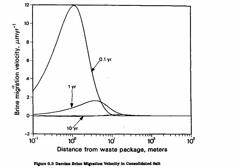
icr io' irf Distance from waste package, meters
10
Figure 6.3 Darcian Brine Migration Velocity in Consolidated Salt
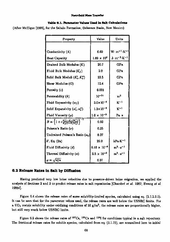
Naur-field MM* IVansfar
TabW 6.1. F u u t t t w ValoM UNd in Salt Calculations (After McTigue [1986], for the Salado Formation, Delaware Basin, New Mexico)
Property Value Units
Conductivity (A)
Heat Capacity
6.60
1.89 x 10⁶
W m - ' K " 1
J- m-^K" 1
Drained Bulk Modulus (K)
Fluid Bulk Modulus (£/)
Solid Bulk Moduli (K'„K',')
Shear Modulus (G)
Porosity (c)
Permeability (it)
Fluid Expansivity (07)
Solid Expansivity (a',,a")
Fluid Viscosity (ft)
20.7
2.0
23.5
12.4
0.001
io- 2 1
3.0xl0- 4
1.2x10-"
1.0 x lO" 3
GPa
GPa
GPa
GPa
m s
K- 1
K- 1
P a s
Poisson's Ratio (u)
Undrained Poisson's Ratio (</„)
6', Eq. (2a)
Fluid Diffusivity (rf)
Thermal DifTusivity (K)
0.93
0.25
0.27
29.0
0.16 x 10- 6
3.5 x lO"6
0.21
kPaK" 1
m ' - s - 1
m ' s " " 1
6.2 Release Rates In Salt by Diffusion Having predicted very low brine velocities due to pressure-driven brine migration, we applied the
analysis of Sections 2 and 3 to predict release rates in salt repositories [Chambre et at. 1987; Hwang et al. 1989d].
Figure 6.4 shows the release rates of some solubility-limited species, calculated using eq. (2.1.2.2.1). It can be seen that for the parameter values used, the release rates are well below the USNRC limits. For a UO2 matrix solubility under oxidizing conditions of 50 g/m 3, the release rates are proportionally higher, but still very much below USNRC limits.
Figure 6.5 shows the release rates of 1 3 7 Cs, 1 3 5 Cs and 1 2 9 I for conditions typical in a salt repository. The fractional release rates for soluble species, calculated from eq. (3.1.15), are normalized here to initial
68

69 i
Fractional release rate, year"
0>
I f I i g
I I (I
I i
i i i 1 1 1 1 i'i CJ1 X
Fractional release rate, year - i

c Ll
lUlll
10"i C s 1 3 6
x— 1 I—
110"7| (D :
£ Iff6! <o -<0
£ 10"S
C s * "
° c NRC Limit \™ •S icf10, o = l _
Li.
icr"i
for Cs 1 3 7
\™
i r f 1 2
\\j • 111 ii| i i i 1111 • | i 111 nil i i 1111II
10° 10' 1lf 10" 10' 10" Time since emplacement, years
10°
Figure 6.5 Fractional Release Rates of Some Soluble Species in Salt

Nur-fUld Maaa IVuwfar
inventories and assuming that waste is exposed to brine shortly after emplacement. It is assumed that one percent of the total inventory of cesium and iodine is present as readily soluble species in the fuel. The dissolution of cesium and iodine species by congruent dissolution from the waste matrix (Section 3.1) is also calculated but is much smaller than the contribution from readily soluble material, and has been neglected in Figure 6.4.
The release rates of 1 3 5 C s and l 2 9 I are below the calculated release rate limits at all times shown in Figure 6.5. The calculated limit for 1 3 7 C s is exceeded for some 300 years, if no waste container is present. A container with a life of 300 years will allow sufficient decay time for the calculated limit for 1 3 7 C s to be met.
6.3 Steady-State Mai* Transport in Salt Interbeda While the salt is known to be quite pure in salt domes, bedded salt is interlaced with beds of sediments.
Traditionally rock salt has been considered almost incapable of conducting water, but sediment layers arc classical porous media, capable of conducting water. Therefore, there is interest in determining whether inlcrbcds in bedded salt constitute a significant pathway for radionuclide migration.
In this Section we consider steady-state migration of radionuclides from a single waste cylinder into a single interbed. Two approaches are used. In 1982 Nerctnieks (Andersson, Rasmuson and Ncrctnieks, 1082] proposed an approach for calculating the steady-state transport of oxidants to a copper container. We have adapted that approach for calculating steady-state radionuclide migration away from the waste package.
The situation studied is shown in Figure 6.6. A wtiste package is inserted into an emplacement hole in a salt repository and backfilled with crushed salt. The emplacement hole intersects an interbed. Given the large number of interbcds observed in cores near some prospective salt sites, an interbed intersection is probable. The following assumptions are used. • The crushed salt has consolidated to the extent that there is no flow within the crushed-salt region. • There is ground water flow in the interbed and the velocity is constant. • The interbeds are planar and and parallel and are perpendicular to the longitudinal axis of the waste cylinder. • The interbeds are uniformly spaced. • The waste cylinder is sufficiently long so that end effects can be ignored. • In calculating temperature effects we use constant values of parameters such as diffusion coefficients, but for the highest temperatures expected. • The surrounding salt is impervious to water flow and radionuclide transport. • Steady-state conditions prevail.
With these assumptions, the problem reduces to one of one-dimenional diffusion. For a nuclide to move from the waste cylinder where it is at a higher concentration to the flowing ground water in the interbed where it is at a lower concentration, the problem can be conceptualized as
m = —-—• —c, (6.3.1)
where m is the mass transport rate, c is the species concentration, A the area over which mass transport is taking place and w a mass transfer coefficient, and the subscripts c and i refer to the crushed salt and interbeds respectively, c, is the solubility at the waste.
71

l l t t l l l W A V / V / V A V / V . . V \ \ % \ \ \ S \ \ S S V \ \ % V '
V
1
-|fniiT»wi-n-i aww)MiiiwwwMw» N A N A A A A A N A A N N N mut ,\\\\\\%\\\\\%\\
> A A A. A A A A A A \
*^ +* *^ *^ '. *^ '*. **. *.. '.
wmx? \ \ \ \ s \ \ \ \ \ \ 1
61 72
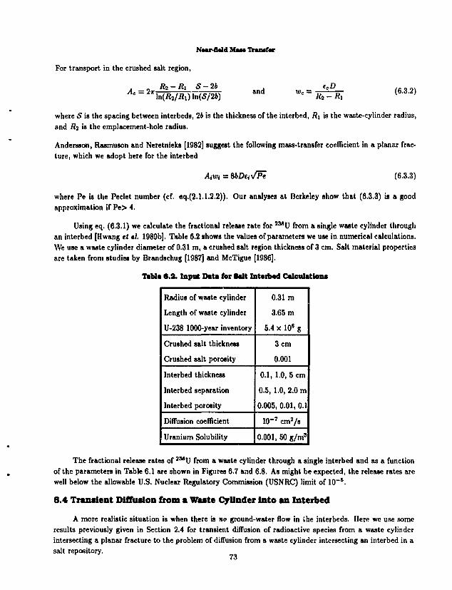
NMT-flald M*M Tk*n*f«r
For transport in the crushed salt region,
. „ Rj-Ri 5 - 2 6 ecD . . A° = 2*MR2/R1)Msm a n d *• = !£=*; < 6 - 3 - 2 >
where 5 is the spacing between interbeds, 26 is the thickness of the interbed, R\ is the waste-cylinder radius, and Rj is the emplacement-hole radius.
Andersson, Rasmuson and Neretnieks [1982] suggest the following mass-transfer coefficient in a planar fracture, which we adopt here for the interbed
AiWi = SbDuVPe (6.3.3)
where Pe is the Peclet number (cf. eq.(2.1.1.2.2)). Our analyses at Berkeley show that (6.3.3) is a good approximation if Pe> 4.
Using eq. (6.3.1) we calculate the fractional release rate for 2 M U from a single waste cylinder through an interbed [Hwang tt al. 1989b]. Table 6.2 shows the values of parameters we use in numerical calculations. We use a waste cylinder diameter of 0.31 m, a crushed salt region thickness of 3 cm. Salt material properties are taken from studies by Brandschug [1987] and McTigue [1986].
Itbte 6.2. Input DnU for Salt Int«rb«d Calculation*
Radius of waste cylinder
Length of waste cylinder
U-238 1000-year inventory
0.31m
3.65 m
5.4 x 10e g
Crushed salt thickness
Crushed salt porosity
3 cm
0.001
Interbed thickness
Interbed separation
Interbed porosity
0.1, 1.0, 5 cm
0.5, 1.0, 2.0 m
0.005, 0.01, 0.1
Diffusion coefficient lO" 7 cm 2/s
Uranium Solubility 0.001, 50 g/m 3
The fractional release rates of J M U from a waste cylinder through a single interbed and as a function of the parameters in Table 6.1 are shown in Figures 6.7 and 6.8. As might be expected, the release rates are well below the allowable U.S. Nuclear Regulatory Commission (USNRC) limit of 10~ s.
6.4 Transient Diffusion from a Waste Cylinder into an Interbed A more realistic situation is when there is no ground-water flow in the interbeds. Here we use some
results previously given in Section 2.4 for transient diffusion of radioactive species from a waste cylinder intersecting a planar fracture to the problem of diffusion from a waste cylinder intersecting an interbed in a salt repository.

n
Fractional release rate, per year
! a
2 CD
CD
* Z c 3 cr CD
Q Fractional release rate, per year
U solubility 50 ppm
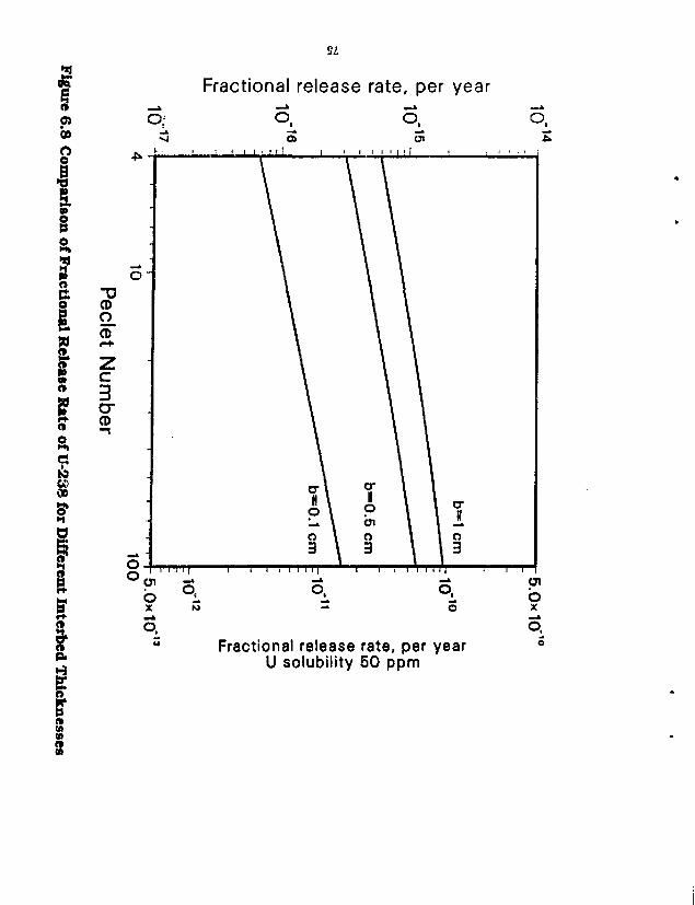
ez
* 1 0)
I § e
r i i I o
10 ee 00 3*
I I
i n w » o (A
Fractional release rate, per year
o . o .
o. o. Fractional release rate, per year
U solubility 50 ppm
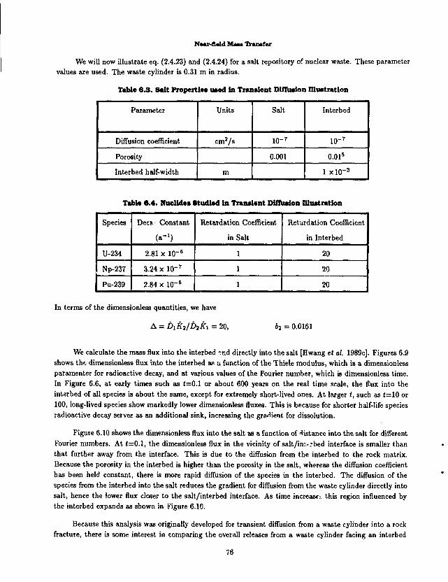
Naar-fialcl Man Transfer
We will now illustrate eq. (2.4.23) and (2.4.24) for a salt repository of nuclear waste. These parameter values are used. The waste cylinder is 0.31 m in radius.
Table 6.3. Salt Properties used in Transient Diffusion Illustration
Parameter Units Salt Interbed
Diffusion coefficient cm 2/s io- 7 io- 7
Porosity 0.001 0.015
Interbed half-width m 1 xlO- 3
Tabla 6.4. Nuclides Studied in Transient Diffusion Illustration
Species Dec? Constant
(a" 1)
Retardation Coefficient
in Salt
Retardation Coefficient
in Interbed
U-234 2.81 x 10- 6 1 20
Np-237 3.24 x 10- 7 1 20
Pu-239 2.84 x 10" 5 1 20
In terms of the dimensionless quantities, we have
A = Dikilbiki = 20, 62 = 0.0161
We calculate the mass flux into the interbed ^nd directly into the salt [Hwang et at. 1989c]. Figures 6.9 shows the dimensionless flux into the interbed as a function of the Thiele modulus, which is a dimensionless paramenter for radioactive decay, and at various values of the Fourier number, which is dimensionless time. In Figure 6.6, at early times such as (=0.1 or about 600 years on the real time scale, the flux into the interbed of all species is about the same, except for extremely short-lived ones. At larger (, such as (=10 or 100, long-lived species show markedly lower dimensionless fluxes. This is because for shorter half-life species radioactive decay serves as an additional sink, increasing the gradient for dissolution.
Figure 6.10 shows the dimensionless flux into the salt as a function of distance into the salt for different Fourier numbers. At (=0.1, the dimensionless flux in the vicinity of sa!t/im...-bed interface is smaller than that further away from the interface. This is due to the diffusion from the interbed to the rock matrix. Because the porosity in the interbed is higher than the porosity in the salt, whereas the diffusion coefficient has been held constant, there is more rapid diffusion of the species in the interbed. The diffusion of the species from the interbed into the salt reduces the gradient for diffusion from the waste cylinder directly into salt, hence the lower flux closer to the salt/interbed interface. As time increase: this region influenced by the interbed expands as shown in Figure 6.10.
Because this analysis was originally developed for transient diffusion from a waste cylinder into a rock fracture, there is some interest in comparing the overall releases from a waste cylinder facing an interbed
76

* * • »
1.6
^ 1.4-
• o o -£ 1.2
O 1
X 3
CO CO
_© c o
'co c E
0.8 -
S£ 0.6
0 .4 -
0.2
t « 0.1 ( *600 yr)
• -
237 Np
10
234 U -3 | ' ' ' " " ' . 2 | ' ' '
10 i i i | i i I i i i n ; —
10"' 10° I M i l l ]
10' Thiele modulus, A
Figure 6.9 Effect of Decay and Time on Mass Flux to the Interbed

600 yr)
t - 1
1
10
i 2 -V 2 D 2 c , /a
0 | I I l l l l | I—I I I l l l l | I I I I M i l l " I I I I l l l l | t i l l l l l l | I |
3.0*10"210"1 10° 101 102 1033.0*103
Distance from salt/interbed interface, meters
Figure 6.10 Diffusive Flux from the Waste Cylinder Directly into the Salt
4 * § •
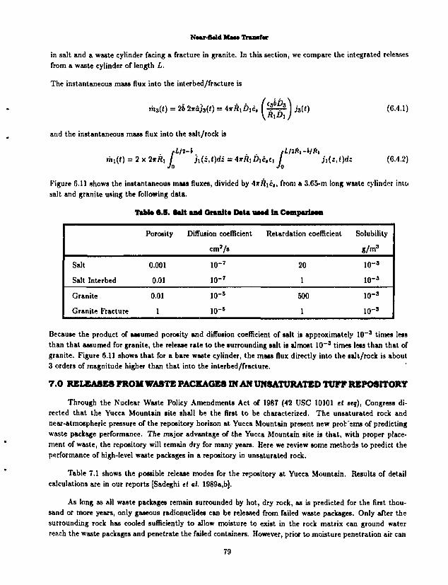
Naar-fiald MIH Trtaamtmt
in salt and a waste cylinder facing a fracture in granite. In this section, we compare the integrated releases from a waste cylinder of length L.
The instantaneous mass flux into the interbed/fracture is
m,(() = 26 2*0/3(1) = 4jrfl,6 Ic. V-^A h{t) (6.4.1) \R\DiJ
and the instantaneous mass flux into the salt/rock is
A/,/2-1 fL/i(i,-i/tt> nn(<) = 2 x 2*rt, / Ji(i,O<tt = 4*fl!0|C.ei / h{:J)d: (6.4.2)
Figure 6.11 shows the instantaneous mats fluxes, divided by -\xR\c,, from a 3.65-m long waste cylinder into salt and granite using the following data.
Tabte 6.5. Salt and Qrmnlta Data HM4 In Cawparia—
Porosity Diffusion coefficient
cm*/s
Retardation coefficient Solubility
SM3
Salt 0.001 10- 7 20 10" 3
Salt Interbed 0.01 io- r 1 10- 3
Granite 0.01 10" 5 500 lO" 3
Granite Fracture 1 10 _ s 1 10- 3
Because the product of assumed porosity and diffusion coefficient of salt is approximately 10~3 times less than that assumed for granite, the release rate to the surrounding salt is almost 10" 3 times less than that of granite. Figure 6.11 shows that for a bare waste cylinder, the mass flux directly into the salt/rock is about 3 orders of magnitude higher than that into the interbed/fracture.
7 . 0 RELEASES FROM WASTE PACKAGES IN AN UNSATURATED TUFF REPOSITORY
Through the Nuclear Waste Policy Amendments Act of 1987 (42 USC 10101 et seq), Congress directed that the Yucca Mountain lite shall be the first to be characterized. The unsaturated rock and near-atmospheric pressure of the repository horizon at Yucca Mountain present new profc'ems of predicting waste package performance. The major advantage of the Yucca Mountain site is that, with proper placement of waste, the repository will remain dry for many years. Here we review some methods to predict the performance of high-level waste packages in a repository in unsaturated rock.
Table 7.1 shows the possible release modes for the repository at Yucca Mountain. Results of detail calculations are in our reports [Sadeghi tl at. 1989a,b],
As long as all waste packages remain surrounded by hot, dry rock, as is predicted for the first thousand or more years, only gaseous radionuclides can be released from failed waste packages. Only after the surrounding rock has cooled sufficiently to allow moisture to exist in the rock matrix can ground water reach the waste packages and penetrate the failed containers. However, prior to moisture penetration air can
79

10"%
IO - 2 J
icrS
tf\
INTO GRANITE
10"
Into granite fracture
Into salt interbed T T m
16 2
Time Since Emplacement, years
i i n i I I i i i i 11111 i i i i 11111 i i i i • 1111 ,
101 102 103 104 106
Figure 6.11 Total Man Flux of a Stable Nuclide from a 3.65-m Long Waste Cylinder in Salt and Granite

N*ar-fl*ld Mas* TV»n»f«r
enter failed containers. Air inleakage can oxidize Zircaloy cladding and mobilize more gaseous carbon-14. Oxidation of the uranium dioxide can cause additional cladding failures. The oxidized uranium will be more soluble, and contained radionuclides can be dissolved more readily if later exposed to ground water.
Table 7.1. Release Modes at Tucca Mountain
Environment Species
Gaseous Low-Solubility Instant-Release Alteration-Controlled
Hot-Dry y/ No Release No Release No Release
Ambient y/
Wet Drip
or
Wet Continuous
Wet Drip
or
Wet Continuous
Wet Drip
or
Wet Continuous
Saturated No Release Wet Continuous Wet Continuous Wet Continuous
7.1 The Wet-Drip Scenario
At Yucca Mountain each waste package is to be emplaced in a borehole, with a 2-cm air gap between the container surface and the surrounding rock [USDOE 1988]. The 0.2-m air gap between the container and the surrounding rock is designed to keep the container from contacting the rock. Water will contact the waste package only if there is some variation of the local environment away from the design condition, e.g., dripping from overhead rock or contact with moist rock [O'Connell 1990]. Possible variations in rock permeability may divert water into fractures that intersect the emplacement hole, possibly resulting in drips onto the package [O'Connell and Drach 1986]. However, even when the surrounding rock has reached an equilibrium moisture content, the repository is not expected to be saturated. The drips are assumed to cause local cracks in the container. We conservatively assume that all of the water dripping onto the container enters the cracks s:.d contacts spent fuel, and we neglect protection of the UOj fuel by the Zircaloy cladding. For a scenario to predict the possible magnitude of radionuclide releases to ground water, the Lawrence Liverrnore National Laboratory assumes that ground water drips from the rock above the waste package and penetrates through cracks and holes in failed containers. If there arc no bottom-exit pathways, water can dissolve radionuclides as it slowly fills the container. Assuming that contaminated water can escape from other top penetrations and drip onto the rock below, the release rate after container overflow can be estimated for a low-solubility species by multiplying the volumetric flow rate by the elemental solubility and by the time-dependent atom fraction of the isotope in the element. The Zircaloy cladding is assumed to present no barrier to release of radionuclides to water within the container. Liquid within the container is expected to be well mixed at all times from diffusion and thermal convection. The water flow rate into the failed container is assumed to be the product of the ambient Darcy velocity in the surrounding tuff and the cross-sectional area of the waste package. Smaller or larger flow rates may occur, depending on the extent to which water is channeled transversely in fractures above the waste packages.
The results of Sadeghi ei al. [1989b] calculated for plutonium in spent fuel and borosilicate glass, are shown in Figure 7.1. The mass release rate of each isotope is normalized to the 1000-year inventory of that isotope. The solubilities are from Bruton's EQ3/6 calculations [Wilson and Bruton 1989; Bruton 1988]. The estimated void volume within the spent-fuel container is 1.5 m 3. For an estimated Darcy velocity
81
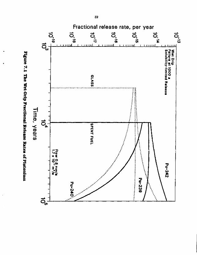
58
Fractional release rate, per year o.
I a a e I
f
I ^ « ' • " l ~ ~ l " " l *~\ ^ " l <o co <3 a> Si * to
I I I l l l l l l I I I I l l U i i i i m i l l i l l m i l l i i i m i l l i i i i n n
3 CD
< CD 0 ) —% CO

NMr-fUld H I H Trmtmttt
of 0.5 mm/a, [USDOE 1988] the spent-fuel-container fill time is about 8,000 years. Assuming first water penetration at 1,000 years, the first overflow release from the spent fuel container is at 9000 years. The release rate of 6,580-yr Pu-240 decreases rapidly with time because of decay, allowing greater concentrations of the longer-lived Pu-239 and Pu-242 within the constraints of elemental solubility. As 24,400-yr Pu-239 decays, greater solubility-limited concentrations of 379,000-yr Pu-242 are possible, and its release rate increases. The curves are calculated to 100,000 years to illustrate the effect of longer time periods that may be considered. For these parameters, the predicted fractional release rates for plutonium and other low-solubility actinides would fall below the USNRC fractional-release limits, even if those linvts were conservatively assumed to apply to individual waste packages rather than to the repository-average release rates.
Results for plutonium released from glass defense waste are also shown in Figure 7.1. The release begins earlier than for spent fuel because of the smaller void volume of 0.42 in3 within the defense waste package. The predicted fractional release rate of a species increases with solubility and decreases with increasing inventory. As compared with spent fuel, the lower solubility predicted for plutotiium in defense waste overcomes the lower inventory, resulting in a three-fold lower release rate than for spent fuel.
Fractional release rates of readily soluble cesium and iodine that exist in fuel-cladding gap, fuel plenum, and grain boundaries are shown in Figure 7.2 [Sadeghi tt al. 1989b]. The liquid in the failed container is assumed to be well mixed at all times, from diffusion and thermal convection, so the release rate falls off exponentially after the first overflow.
Some of the highly soluble species in the waste matrix may not be release-limited by their solubilities. Laboratory studies suggest that their release may be congruent with the alteration of the waste matrix when it reacts with water, such as conversion of UO2 in spent fuel to U3O7 and the conversion of silica in liorosilicate glass to a crystalline mineral phase. Present data are not sufficient to estimate alteration rates, but for illustration we assume a constant mass rate of alteration equivalent to a fractional rate of 0.001/a of the initial inventory of uranium in spent fuel or of silica in defense waste.
The predicted fractional rates [Sadeghi et al. 1989b] of Tc-99 released by waste-matrix alteration are shown in Figure 7.3 for spent fuel and defense waste. The first liquid overflow is at an average concentration resulting from the slow rise of liquid level in the container. Only at the time of overflow will all of the waste matrix h*ve been exposed to water for alteration and release. The average concentration of long-lived species in the filled container increases further with time, and their release rates increase, until all of the waste matrix has altered and all soluble constituents are dissolved. For the rate constant assumed here, the last waste-solid alteration will be complete l.'.'OO years after first overflow. The release then decreases exponentially with time as fresh ground water mixes uniformly with the container liquid. These results are only for illustration. Better data are needed to estimate alteration rates appropriate for this calculation.
The release rates of cesium and technetium could be limited instead by solubility. Low-solubility pollu-cite [(Cs.NaJjAljSUOu-HzO] can be formed by cesium and silica from borosilicate glass [Bennington, Beyer and Johnson, 1983]. Bruton's calculations show that water-waste reactions can result in an increasingly reducing environment [Wilson and Bruton 1989; Bruton 1988] that can promote a lower solubility of technetium. Also, the iron container is expected not to fail by uniform corrosion but by local penetrations, so iron-water reactions within the container can contribute further to a reducing environment.
The aiteration-contiolled release rates for borosilicate-glats waste show greater peak values than lor spent fuel and decay more rapidly after the peak. This is a consequence of the smaller void volume within
83

inn IIIIIIIII iniriiM IIIIIIIII IIIIIIIII IIIIIIIII IIIIIIIII IIIIIIIII IIIIIIIII
o 'o 'o 'o 'o 'o 'o 'o 'o v_ * T— x— t-~ T-" r— *"* t— t~- V-* r—
jeeA jed 'e;ej eseejej leuoiioejj 84

10"%
10_%
10 r IO
10°
Wet Drip Alteration Hate 0.001/a Container fails at 1000 a
GLASS
~i 1 1 1 — I — I I | T 1 1—I—I -r
10 Time since failure, years
10°
Figure 7.3 The Wet-Drip Fractional Release Rate of Tc-99

Nwtr-tMd Maw Trancf«r
the defense-waste container.
7.2 The Wet-Continuous Scenario
The wet-drip scenario assumes that there are no pathways for diffusive release to the surrounding rock. However, part or all of the degraded container can make contact with surrounding rock or with exfoliated rock and rubble that may fill the annular space around the container. Diffusive pathways through the degraded container and into the surrounding rock are possible. If a diffusive pathway exists, then all of the techniques reviewed in Sections 2 and 3 are applicable. We have shown [Sadeghi et ai. 1990] that diffusive mass transfer through the porous media surrounding the waste can result in release rates greater than those estimated for the wet-drip scenario, depending on the magnitude of the diffusion coefficient. Here we show the results of diffusive mass-transfer calculations, using analytic equations from Sections 2 and 3 (Sadeghi et al. 1989b], Conservatively, we neglect mass-transfer resistance from fuel cladding and failed metal containers,
Solubllltjr-Limlted Releases
The time-dependent fractional release rate of a low-solubility species from an equivalent spherical waste can be calculated from the equations in Section 2.1.2. The fractional release rate is the mass release rate divided by the 1000-year inventory. Decay within the waste solid is neglected. For a saturated repository, or if a significant portion of the degraded container is in contact with surrounding intact rock, we obtain the results from plutonium isotopes from spent fuel shown in Figure 7.4. Long-term release is greater for the shorter-lived species because decay steepens the concentration gradient at the waste surface. For the parameter values used, [USDOE 1988; Wilson and Bruton 1989] the predicted release rates are far below the regulatory limits but are greater than those predicted for a drip scenario.
If the annulus becomes filled with rubble and fines consolidated to the same consistency as intact rock, the consolidated annulus acts as a buffer. The resulting fractional release rate, calculated using eq. (2.3.1.9), across the original borehole surface is shown in Figure 7.5 for plutonium isotopes. The 2-cm buffer delays release of plutonium into the original rock, and it eliminates the early-time high release rate.
If the rubble and fines in the annulus do not consolidate, and if the repository is not saturated, diffusion through the rubble bed is inhibited by the small area of contact between individual rubble pieces [Sadeghi et ai 1990]. Assuming a 1,000-fold reduction in the effective mass transfer coefficient in the rubble compared to intact rock, we obtain the resulting time-dependent fractional releases of plutonium isotopes into the surrounding intact tuff are shown in Figure 7.6. The peak release rate is about 500-fold below that calculated in Figure 7.5.
Alteration-Controlled Releases
Soluble species in the spent-fuel matrix can be released directly to the rock by solid-phase alteration of spent-fuel matrix. If the release is congruent with alteration, the fractional release rate will equal the fractional alteration rate of the uranium. If the fractional alteration ra*« is as high as lO" 1 to 10~ 3/a, as might occur in an oxidizing environment, alteration-controlled release can be of concern in meeting regulatory limits.
86
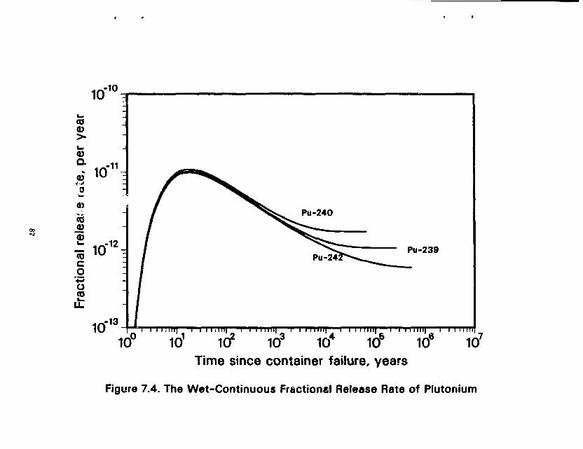
10 10
CO CD >
Pu-240
Pu-239
10' 1(7 10;
Time since container failure, years
I I I I 11! I inil) i i 11f• • 11 i i i I I I I I I
104 106 106 107
Figure 7.4. The Wet-Continuous Fractionel Release Rate of Plutonium

88
Fractional release rate, per year
<5" c ~i a - j bi
3« °"£
= o 3 5' c o c 0» 01 o o* 3 0»_ 30 2. a « 3 a O
<V
O-
H 3 (i) —* : CO qr 3 O -CD O —A :
o 3
<V i-+ 0> . 3 -erf
11 III
104
2. . c --» -© * —A :
<V CO
o 3 t 5' 3 o;

10 13
I I I I t i l l
10° 10'
Pu-240
Pu-242
I I I I I Ij I I I I I I
id 2 io" io" iow ia Time since container failure, years
i iinii i i i HIIII i i i Mini i i i inn' 10 4 10 5 10 6 107
Figure 7.6. The Wet-Continuous Fractional Release Rate of Plutonium 2 cm backfill, 1,000-fold reduction in diffusion coefficient

Near-Bald Mas* Transfer
P.O SUMMARY
The foregoing is a comprehensive review of much of our research results on predicting near-field mass transfer. Further work is in progress and will be published separately.
Readers should refer to the original reports for details of mathematical derivations:, methods of solutions and calculations.
ACKNOWLEDGEMENT
Work supported in part by the Director, Office of Civilian Radioactive Waste Management, Office of Systems Integration and Regulation, Licensing and Compliance Division, under contract DE-AC03-76SF00098.
NOTATION
A is the area over which mass transport is taking place a is the dimension of gap or void
B is the pore-pressure modulus, where — = 1 + e-pr-r.—Z~ in \
B is a geometrical factor b' is a constant involving materia) properties, eq. (6.1.2) b = R0 — R is the thickness of the backfill bx is the semiminor axis of a prolate spheroid i 2 = t3iKa/€iRiku eq. (2.4.16) 26 is the thickness of a rock fracture/salt interbed c is the concentration of the species ci is the concentration in the backfill (Layer 1) ci is the concentration in the rock (Layer 2) C3 is the concentration in the fracture c 4 is the concentration in Layer 1 after precipitation starts C5 is the concentration in Layer 2 after precipitation starts c„ is the mass of the species adsorbed on the solid phase per unit bulk dry mass of the [ orous material c° is the initial concentration of the species in the void water cr is the solubility limit after precipitation Cj is the saturation concentration c* is the average concentration of the nuclide outside of the backfill c* is the critical concentration c'(t) is the time-dependent well-mixed concentration of the soluble species in the water in the void c is the concentration in the unsaturated zone d is fluid diifusivity, eq. (6.1.2) D is the diffusion coefficient Df is the diffusion coefficient for the liquid continuum Vj is the one-dimensional finite domain E( i ) is the complete elliptic integral of the second kind, and £ is the eccentricity of a prolate spheroid / is the fractional dissolution rate of the species /(<), g(t) are dimensiocless functions of time
90
Naar-Oald MM* DruMfar
T is the saturation concentration in the solid phase G is the shear modulus Q{i) is the location of the saturation front h is a mass transfer coefficient jo is the experimental forward reaction rate of the dissolved species per unit surface area ji(z,t) is the dimensionless flux into the fracture/interbed j3(t) is the dimensionless flux directly into the rock/salt k is the permeability ki is the mass-transfer coefficient for the spherical waste surface kj is a reaction-rate constant K is the species retardation coefficient A'd is the sorption distribution coefficient K is the bulk modulus, eq. (6.1.2) AC/ is the fluid bulk modulus K,', K" are the solid bulk moduli L is the length of the waste cylinder M is the inventory M is the number of isotopes in an element m is the mass flux mj(t) is the rate of dissolution of the species from the waste matrix into the void volume V me is the mass transfer rate of the controller or dominant species M is the total mass loss from the surface of the waste solid M is the bulk density of the elemental species in the waste P is the relative pore pressure Pe= UR/D the Peclet number q(f, t) is the diffusive flux from the fracture to the rock through the interface Qa is the initial heat flux of the waste package (2„(<0 = ln(coth<;/2) rp is the location of the precipitation front R is the radius of spherical waste solid Ro is the radius of waste sphere including backfill Ri is the waste cylinder radius R? is the emplacement hole radius Rp is the location of the precipitation front S is the surface area of gap or void S is the spacing between interbeds Sh=kiR/eD is the Sherwood number t is time tp is the time of precipitation onset t, is the time necessary for the mass flux at the surface to reach within Ave percent of the steady-state value 7i is the breakthrough time T is the temperature U is the ground-water pore velocity upstream of the waste solid V is the volume of gap or void v is the Darcy velocity w is a mass transport coefficient in salt
91

N«ai>flald Mau Tramfcr
i is the distance from the rock/fracture interface a = joRjcDc, is the Thiele modulus aj is the fluid-phase thermal expansion coefficient a" is the second cubical thermal expansion coefficient of the solid 0=y/DoKc*/a? /?i -• y/KyK[ in eq. (2.3.1.9) 7 is the isotopic fraction S(j is the Kronecker delta
* = v f e e q ' ( ! m i )
c is the porosity of the rock <;" is the prolate spheroid surface coordinate 0 is relative temperature K is the thermal diffusivity A is the species decay constant A is the thermal conductivity It is the absolute viscosity u is Poisson's ratio for the solid phase vu is the undrained Poisson's ratio (4(c, c„) is the interphase reaction rate w = Ut/KR <TI and <r2 are tortuosity correction factors for the two layers T=(l + a):>Dt/KRi
Qi = K\R?/D Q2 = KXR/U is the Thiele modulus for convective mass transport u = A'ie,5/V, eq (3.2.11) p = cosh - 1 (l/£) prolate spheroid coordinate
SUBSCRIPTS
c crushed salt region e element i isotope or interbed s stable or solubility se elemental solubility f fluid phase s solid phase 1 backfill or Layer 1 or inner layer 2 rock or Layer 2 or outer layer
92
REFERENCES
Ahn, J., P. L. Chambre, and T. H. Pigford, Transient Diffusion From a Cylindrical Waste Solid Into Fractured Porous Rock, Rad. Waste Mgt & the Nucl. Fuel Cycle, 13, 263, 1989.
Ahn, J., P. L. Chambre, T. H. Pigford, and W. W.-L. Lee, Radionuclide Dispersion From Multiple Patch Sources Into a Rock Fracture, Report LBL-SS4S5, Lawrence Berkeley Laboratory, 1987.
Ahn, T. M., K. S. Czyscinski, E. M. Franz, C. J. Kiamut, B. S. Lee, N. S. Mclntyre, K. J. Swyler, and R. J. Wilke, Nuclear Waste Management Technical Support in the Development of Nuclear Waste Form Criteria for the NRC, Report NVREG/CR-2888-4, Brookhaven National Laboratory, 1982a.
Ahn, T. M., R. Dayal, and R. J. Wilke, Evaluation of Backfill as a Barrier to Radionuclide Migration in a High Level Waste Repository, Report NUREG/CR-SSSS. App. A, Brookhaven National Laboratory, 1982b.
Andersson, G., A. Rasmuson, and I. Neretnieks, Migration model for the near field, Final Report, Report SKBF/KBS Report 82-24, 1982.
Bennington, K. 0. , R. P. Beyer, and G. K. Johnson, Thermodynamics Properties of Pollucite, Report Report of Investigations 8779, U. S. Bureau of Mines, 1983.
Brandshaug, T., Estimate of Consolidation of Crushed Salt Around a Spent Fuel Waste Package, Report RSI-8J5, RE/SPEC Inc., 1987.
Browne, E., and R. B. Firestone, Table of Radioactive Isotopes, Wiley, New York, 1986.
Bruton, C. J., Geochemical Simulation of Dissolution of West Valley and DWPF Glasses in J-13 Water at 90 C, in Scientific Basis for Nuclear Waste Management XI, edited by M.J. Apted, and R.E. Westerman, Materials Research Society, 607, 1988.
Campbell, J. E., and R. M. Cranwell, Performance Assessment of Radioactive Waste Repositories, Science, 239, 1389, 1988.
Chambre, P. L., Y. Hwang, W. W.-L. Lee, and T. H. Pigford, Release Rates from Waste Packages in a Salt Repository, Trans. Am. Nucl. Soc, 55, 131, 1987.
Chambre, P. L., C. H. Kang, W. W.-L. Lee, and T. H. Pigford, Mass Transfer of Soluble Species Into Backfill and Rock, Trans. Amer. Nuc. Soc, 5S, 136, 1986.
Chambre, P. L., C. H. Kang, W. W.-L. Lee, and T. H. Pigford, The Role of Chemical Reaction in Waste-Form Performance, in Scientific Basis for Nuclear Waste Management XI, edited by M.J. Apted, and R.E. Westerman, Materials Research Society, 125, 1988.
Chambre, P. L., C. H. Kang, and T. H. Pigford, Flow of Ground Water Around Buried Waste, Thins. Am. Nuc. Soc, 52, 77, 1986.
Chambre, P. L., H. Lung, and T. H. Pigford, Time-Dependent Mass Transfer Through Backfill, Trans. Amer. Nucl. Soc, 46, 132, 1984.
Chambre, P. L., and T. H. Pigford, Prediction of Waste Performance in a Geologic Repository, in Scientific Basis for Nuclear Waste Management VIII, edited by G.L. McVay, Materials Research Society, 985, 1984.
Chambre, P. L., T. H. Pigford, W. W.-L. Lee, J. Ahn, S. Kajiwara, C. L. Kim, H. Kimura, H. Lung, W. J. Williams, and S. J. Zavoshy, Mass Transfer and Transport in a Geologic Environment, Report LBL-19480, Lawrence Berkeley Laboratory, 1985.
Chambre, P.L., T. H. Pigford, Y. Sato, A. Fujita, H. Lung, S. J. Zavoshy, and R. Kobayashi, Analytical Performance Models, Report LBL-14842, Lawrence Berkeley Laboratory, 1982.
R-l
Chambre, P. L., W. 3. Williams, C. L. Kim, and T. fl. Pigford, Time-Temperature Dissolution and Radionuclide Transport, 7Van5. Am. Nuc. Soc, 46, 131, 1984.
Garisto, F., Solid Dissolution: Effect of Mass Transport-Precipitation Coupling, Chem. Eng. Sci., 41, 3219, 1986.
Garisto, F., and N. C. Garisto, The Effect of Precipitation on Radionuclide Release from Used Fuel, in Snd Intl Conf. on Radioactive Waste Management, 645, 1986a.
Garisto, N. C , and F, Garisto, The Effect of Precipitation on the Lang-Term Release of Radionuclides from Used Fuel, Ann. Nuc. Energy, 18, 591, 1986b.
Garisto, N. C , and F. Garisto, Mass Transport-Precipitation Coupling ir ir . i i S> •turns, Report AECL-9562, 1988.
Garisto, N. C , K, B. Harvey, F. Garisto, and L. M. Johnson, Source Term nic; . < for the Assessment of Nuclear Fuel Waste, in Waste Management '86, ft, 397,1986.
Garisto, N. C , E. R. Vance, S. Stroes-Gascoyne, and L, H. Johnson, Instant-Release Fractions for the Assessment of Used Nuclear Fuel Disposal, Report AECL-9898, AECL, 1989.
Hwang, Y., P. L. Chambre, W. W. L. Lee, and T. H. Pigford, Pressure-Induced Brine Migration in Consolidated Salt in a Repository, Trans. Am. Nucl. Soc, 55, 132, 1987.
Hwang, Y., P. L. Chambre, T. H. Pigford, and W. W.-L. Lee, Pressure-driven Brine Migration in a Salt Repository, Report LBL-25768, Lawrence Berkeley Laboratory, 1989a.
Hwang, Y., W. W.-L. Lee, P. L. Chambre, and T. H. Pigford, Mass Transport in Salt Repositories: Steady-State Transport Through Interbeds, Report LBL-86704, Lawrence Berkeley Laboratory, 1989b.
Hwang, Y., W. W.-L. Lee, P. L. Chambre, and T. H. Pigford, Mass Transport in Salt Repositories: Transient Diffusion into Interbeds, Report LBL-96703, Lawrence Berkeley Laboratory, 1989c.
Hwang, Y., W. W.-L. Lee, P. L. Chambre, and T. H. Pigford, Release Rates in Salt by Diffusion, Report LBL-85767, Lawrence Berkeley Laboratory, 1989d.
Isayama, Y., W. W.-L. Lee, T. H. Pigford, and P. L. Chambre\ Isotopic Effects of Solubility-Limited Mass Transfer, 7Vsns. Am. Nuc. Soc, 60, 110, 1989.
Kang, C.-H., Mass Transfer and Transport of Radionuclides Through Backfill in a Geologic Nuclear Waste Repository, Ph. D., University of California, Berkeley, 1989.
Kang, C. H., P. L. Chambre, and T. H. Pigford, One-Dimensional Advective Transport with Variable Dispersion, Tram. Am. Nucl. Soc, 50, 140, 1985.
Kang, C. H., and W. W.-L. Lee, UCB-NE-108 User's Manual, Report LBL-S7044, Lawrence Berkeley Laboratory, 1989.
Kerrisk, J. F., Solubility Limits on Radionuclide Dissolution At a Yucca Mountain Repository, Report LA-9995-MS, Los Alamos National Laboratory, 1984.
Kerrisk, J. F., Solubility Limits on Radionuclide Dissolution, in Scientific Basis for Nuclear Waste Management VIII, edited by CM. Jantzen, J.A. Stone, and R.C. Ewing, Materials Research Society, 237, 1986.
Kim, C.-L., W. B. Light, P. L. Chambre, W. W.-L. Lee, and T. H. Pigford, Variable Temperature Effects on Release Rates of Readily Soluble Nuclides, in SPECTRUM '88, 536, 1988.
Kim, C.-L., P. L. Chambre, and T. H. Pigford, Mass-Transfer Limited Release of a Soluble Waste Species, Trans. Am. Nuc. Soc.,58, 80, 1986.
R-2
Kim, C. L., P. L. Chambre, W. W.-L. Lee, and T. H. Pigford, Radionuclide Transport From an Array of Waste Packages in a Geologic Repository, Trans. Am. Nucl. Soc, 54, 109, 1987.
Lee, W. W.-L., UCB-NE-102 User's Manual, Report LBL-S6700, Lawrence Berkeley Laboratory, 1989a.
Lee, W. W.-L., UCB-NE-107 User's Manual, Report LBL-S667S, Lawrence Berkeley Laboratory, 1989b.
Light, W. B., P. L. Chambre, T. H. Pigford, and W. W.-L. Lee, The Effect of Precipitation on Contaminant Dissolution and Transport: Analytic Solutions, Report LBL-25769, Lawrence Berkeley Laboratory, 1988.
Lung, H.-C, P. L. Chambre, T. H. Pigford, and W. W.-L. Lee, Transport of Radioactive Decay Chains in Finite and Semi-Infinite Porous Media, Report LBL-88987, Lawrence Berkeley Laboratory, 1987.
Lung, H. C , P. L. Chambre, and T. H. Pigford, Nuclide Migration in Backfill With a Nonlinear Sorption Isotherm, Trans. Amer. Nucl. Soc, 45, 107, 1983.
McTigue, D. F., Thermoelastic Response of Fluid-Saturated, Porous Rock, J. Geophy. Res., 91, B9, 9533, 1986.
Neretnieks, I., Transport of Oxidants and Radionuclides Through a Clay Barrier, Report KBS TR-79, 1978.
Nowak, E. J., The Backfill Barrier as a Component in a Multiple Barrier Nuclear Waste Isolation System, Report SAND 79-1109, Sandia National Laboratory, 1979.
O'Connell, W. J., Status of Integrated Performance Assessment of the Waste Packages and Engineered Barrier System, in International High-level Radioactive Waste Management Conference, 1990.
O'Connell, W. J., and R. S. Drach, Waste Package Performance Assessment: Deterministic System Model Program Scope and Specification, Report UCRL-58761, Lawrence Livermore National Laboratory, 1986.
Pederson, L. R., C. Q. Buckwalter, and G. L. McVay, The Effect of Surface Area to Solution Volume on Waste Glass Leaching, Nucl. Tech, 68, 151, 1983.
Pfannkuch, H. O., Contribution a l'etude des deplacement de fluides miscible dans un milieu poreux, Rev. Inst. Fr. Petrol., 8, 215, 1963.
Pigford, T. H., J. O. Blomeke, T. L. Brekke, G. A. Cowan, W. E. Falconer, N. J. Grant, J. R. Johnson, J. M. Matusek, R. R. Parizek, R. L. Pigford, and D. E. White, A Study of the Isolation System for Geologic Disposal of Radioactive Wastes, National Academy Press, Washington, D.C., 1983.
Pigford, T. H., and P. L. Chambre, Mass Transfer in a Salt Repository, Report LBL-19918, Lawrence Berkeley Laboratory, 1985.
Pigford, T. H., and P. L. Chambre, Near-Field Mass Transfer in Geologic Disposal Systems: a Review, in Scientific Basis for Nuclear Waste Management XI, edited by M.J. Apted, and R.E. Westerman, Materials Research Society, 125, 1988.
Pigford, T. H., P. L. Chambre, M. Albert, M. Foglia, M. Harada, F. Iwamoto, T. Kanki, D. Leung, S. Masuda, S. Muraoka, and D. Ting, Migration of Radionuclides Through Sorbing Media: Analytical Solutions - II, Report LBL-11616, Lawrence Berkeley Laboratory, 1980.
Pigford, T. H., P. L. Chambre, and S. J. Zavoshy, Effect of Repository Heating on Dissolution of Glass Waste, Trans. Am. Nucl. Soc, 44, 115, 1983.
Rai, D., and R. G. Strickert, Maximum Concentrations of Actimdes in Geologic Media, Trans. Amer. Nucl. Soc, 33, 185, 1980.
Roddy, J. W., H. C. Claiborne, R. C. Ashline, P. J. Johnson, and B. T. Rhyne, Physical and Decay Characteristics of Commercial LWR Spent Fuel, Report ORNL/TM-9591/V1&R1, Oak Ridge National Laboratory, 1986.
R-3

Ross, B., Models for Calculating Dissolution Rates of High-Level Waste, Nuclear Safety, 28, 362, 1987.
Sadeghi, M. M., W. W.-L. Lee, T. H. Pigford, and P. L. Chambre, The Effective Diffusion Coefficient for Porous Rubble, in 1990 American Nuclear Society Annual Meeting, 1990.
Sadeghi, M. M., T. H. Pigford, P. L. Chambre, and W. W.-L. Lee, Equations for Predicting Release Rates for Waste Packages in Unsaturated Tuff, Lawrence Berkeley Laboratory, 1989a.
Sadeghi, M. M., T. H. Pigford, P. L. Chambre, and W. W.-L. Lee, Prediction of Release Rates for a Waste Repository at Yucca Mountain, Lawrence Berkeley Laboratory, 1989b.
Scott, J. I., and C. M. Koplik, Analytic Models for Assessing the Performance of Engineered Barriers in a Basalt Repository, in Scientific Basis for Nuclear Waste Management VII, edited by G.L. McVay, Materials Research Society, 1077, 1984.
Sherwood, T. K., R. L. Pigford, and C. R. Wilke, Mass Transfer, McGraw-Hill, Now York, 1975.
U.S. Department of Energy, Environmental Assessment: Reference Repository Location, Hanford Site, Washington, Report DOE/RW-0010, 1986.
U.S. Department of Energy, Site Characterization Plan: Yucca Mountain Site, Nevada Research and Development Area, Nevada, Report DOE/RW-0199, 1988.
U.S. Nuclear Regulatory Commission, Disposal of High-Level Radioactive Wastes in Geologic Repositories -Technical Criteria, Code of Fed. Reg., 10, 60.113(a)(l)(ii)(B), 1983.
Van Luik, A. E., M. J. Apted, W. J. Bailey, J. H. Haberman, J. S. Shade, R. E. Guenther, R. 3. Seme, E. R. Gilbert, R. Peters, and R. E. Williford, Spent Nuclear Fuel as a Waste Form for Geologic Disposal: Assessment and Recommendations on Data and Modeling Needs, Report PNL-6SS9, Pacific Northwest Laboratory, 1987.
Wilson, C. N., and C. J. Bruton, Studies on Spent Fuel Dissolution Behavior Under Yucca Mountain Repository Conditions, Report PNL-SA-168SS, Pacific Northwest Laboratory, 1989.
Yung, S. C. , C. F. McLane, R. P. Anantatmula, R. T. Toyooka, and W. K. Terry, Waste Package Preliminary Reliability Analysis Report, Report SD-BWI-TI-S87, Rockwell, 1987.
Zavoshy, S. J., P. L. Chambre, and T. H. Pigford, Mass Transfer in a Geologic Environment, in Scientific Basis for Nuclear Waste Management VIII, edited by CM. Jantzen, J .A. Stone, and R.C. Ewing, Materials Research Society, 311, 1985.
R-4