a review of subsurface drip irrigation and its management€¦ · 1.3 advantages and disadvantages...
TRANSCRIPT

10
A Review of Subsurface Drip Irrigation and Its Management
Leonor Rodríguez Sinobas and María Gil Rodríguez Research Group “Hydraulic of Irrigation” Technical University of Madrid,
Spain
1. Introduction
According to the ASAE Standards (2005), subsurface drip irrigation SDI is “the application of water below the soil surface though emitters* with discharge rates generally in the same range as drip irrigation.” Thus, aside from the specific details pointed out in this chapter, an SDI unit is simply a drip irrigation network buried at a certain depth. There is a wide variety of plants irrigated with SDI all over the world such as herbaceous crops (lettuce, celery, asparagus and garlic), woody crops (citrus, apple trees and olive trees) and others such as alfalfa, corn, cotton, grass, pepper, broccoli, melon, onion, potato, tomato, etc. Over a quarter of a billion hectares of the planet are irrigated and entire countries depend on irrigation for their survival and existence. Growing pressure on the world's available water resources has led to an increase in the efficiency and productivity of water-use of irrigation systems as well as the efficiency in their management and operation. The efficiency of subsurface drip irrigation SDI could be similar to drip irrigation but it uses less water. It could save up to 25% - 50% of water regarding to surface irrigation. Throughout this chapter, the specific characteristics of SDI will be presented and some criteria for its design and management will be highlighted.
1.1 A bit of history
The first known reference of a subsurface irrigation comes from China more than 2000 years ago (Bainbridge, 2001) where clay vessels were buried in the soil and filled with water. The water moved slowly across the soil wetting the plants’ roots. SDI, as we know it nowadays, developed around 1959 in the US (Vaziri and Gibson, 1972), especially in California and Hawaii, as a drip irrigation variation. In the 60s, SDI laterals consisted of polyethylene PE or polyvinyl chloride PVC plastic pipes with punched holes or with punched emitters. These systems used to work at low pressures, depending on water quality and filtration systems. By the 70s, this method extended to crops as citrus, sugar cane, pineapple, cotton, fruit trees, corn, potato, grass and avocado. Its main disadvantages were: the difficult maintenance, the low water application uniformity and the emitters’ clogging due to, mainly, oxid and soil particles. Alternatively, the equipment for SDI installation in the field developed (Lanting, 1975), and the fertilizers’ injection with the irrigation systems started in Israel (Goldberg and
* Note: In SDI, the word emitter is used instead of dripper since the last has a lack of meaning as water does not drip as it does in drip irrigation.
www.intechopen.com

Water Quality, Soil and Managing Irrigation of Crops
172
Shmueli, 1970). Further, the quality of commercial emitters and laterals improved and SDI gained respect over other irrigation methods mainly due to the decrease of clogging. At the beginning of the 80s, factors such as: the reduction of the costs in pipes and emitters, the improvement of fertilizers application and the maintenance of field units for several years promoted the interest in SDI. This has been extended since then.
Fig. 1. Lateral of subsurface drip irrigation.
1.2 Subsurface drip Irrigation in the world
There is a general agreement about the spread of SDI however it is difficult to obtain data to
confirm this trend since the surface irrigated with SDI is counted as a drip irrigation in most
surveys. In the US, the USDA Farm and Ranch Irrigation Survey (USDA-NASS, 2009)
indicates that SDI comprises only about 27% of the land area devoted to drip and subsurface
drip irrigation. Nonetheless, this percentage is continuously increasing over drip irrigation
as farmers substitute their conventional drip irrigation methods by SDI systems. If this
framework continues in the future, SDI would still have a potential increase. In underdeveloped countries, there are many references about the so called low-cost SDI with rudimentary laterals and low emitter pressures that highlight even more, the SDI potential increase. Likewise, this is enhanced by the savings on water and energy.
1.3 Advantages and disadvantages
Experimental evidences of SDI advantages over other irrigation methods, specifically drip irrigation, are vast. Some advantages and drawbacks of this method, compiled by Lamm (2002) and Payero (2005), are shown below.
www.intechopen.com

A Review of Subsurface Drip Irrigation and Its Management
173
Advantages:
The efficiency of water use is high since soil evaporation, surface runoff, and deep percolation are greatly reduced or eliminated. In addition, the risk of aquifer contamination is decreased since the movement of fertilizers and other chemical compounds by deep percolation is reduced.
The use of degraded water. Subsurface wastewater application can reduce pathogen drift and reduce human and animal contact with such waters.
The efficiency in water application is improved since fertilizers and pesticides can be applied with accuracy. In widely spaced crops, a smaller fraction of the soil volume can be wetted, thus further reducing unnecessary irrigation water losses. Reductions in weed germination and weed growth often occur in drier regions.
Hand laborers benefit from drier soils by having reduced manual exertion and injuries. Likewise, double cropping opportunities are improved. Crop timing may be enhanced since the system need not be removed at harvesting nor reinstalled prior to planting the second crop. On the other hand, laterals and submains can experience less damage and the potential for vandalism is also reduced.
Operating pressures are often less than in drip irrigation. Thus, reducing energy costs. Drawbacks:
Water applications may be largely unseen, and it is more difficult to evaluate system
operation and water application uniformity. System mismanagement can lead to under
irrigation, less crop yield quality reductions, and over irrigation. The last may result in
poor soil aeration and deep percolation problems.
If emitter discharge exceeds soil infiltration, a soil overpressure develops around
emitter outlet, enhancing surfacing and causing undesirable wet spots in the field.
Timely and consistent maintenance and repairs are a requirement. Leaks caused by
rodents can be more difficult to locate and repair, particularly for deeper SDI systems.
The drip lines must be monitored for root intrusion, and system operational and design
procedures must employ safeguards to limit or prevent further intrusion. Roots from
some perennial crops may pinch drip lines, eliminating or reducing flows. Periodically,
the drip lines need to be flushed to remove accumulations of silt and other precipitates
that may occur in the laterals. Likewise, operation and management requires more
consistent oversight than some alternative irrigation systems. There is the possibility of
soil ingestion at system shutdown if a vacuum occurs, so air relief/vacuum breaker
devices must be present and operating correctly. Compression of laterals by soil
overburden can occur in some soils and at some depths, causing adverse effects on
the flow.
1.4 Components of SDI units
The typical SDI unit, contrarily to drip irrigation units, is a looped network. It is composed by a submain or feeding pipe, and a flushing pipe that connects all lateral ends (Fig. 1). The looped network enhances the hydraulic variability and thus, the flow variability within the unit is also improved. The pipes and laterals are buried at a certain depth, generally from 7 to 40 cm, supplying the water directly in the crop root area. The flushing pipe eliminates possible sediments or other water suspended elements. Two relief valves may be placed at the head and tail of the feeding and flushing pipes to release the air at the beginning of the irrigation, and to let it pass when irrigation stops. Thus, soil
www.intechopen.com

Water Quality, Soil and Managing Irrigation of Crops
174
particles are not introduced into the laterals. Alternatively, some flushing valves for the lateral end are also developed for that purpose (Fig. 3). A manometer and a flow meter are placed at the unit head to measure the inlet unit pressure and the total unit discharge, respectively. Filters are also installed at the unit head and additional containers with fertilizers and other chemical products are located there, as well.
Fig. 2. Scheme of a typical SDI unit.
Emitters in SDI are similar to drip irrigation, but they generally are impregnated with a
weed killer to reduce root intrusion at the emitter outlet. In countries where herbicides are
forbidden, commercial emitter models are developed with specific geometries to reduce the
risk of root intrusion. Likewise, there are some models with elements such as diaphragm
and geometries inducing vortical movement, to avoid the entrance and deposition of soil
particles (Fig. 3).
(a) (b)
Fig. 3. Elements of SDI units: (a) emitter models and (b) flushing bulb. (Courtesy of NaaDanJain Irrigation).
www.intechopen.com

A Review of Subsurface Drip Irrigation and Its Management
175
1.5 Field installation of subsurface drip irrigation units
The installation of SDI units in the field shows differences with conventional drip irrigation. In most cases, the soil is chiseled to a depth close to the crop roots length prior the layout of laterals. This will also favor the horizontal water movement. Then, the feeding and flushing pipes are laid on trenches dug following the lateral ends keeping an extra space for the connections between pipes and laterals. Once these are done, the other elements such as: valves, relief valves, flow meters can be installed. Finally, all the subsurface elements are buried. Among all the installation tasks, the difficult one corresponds to the deployment of laterals. These are introduced into the soil by one or several plows connected to a tractor (Fig. 4). Care must be taking to ensure the laterals are placed following a straight line and at a proper depth, and also that the lateral spacing stays constant.
Fig. 4. Installation of SDI.
2. Effect of soil on emitter discharge
One of the key differences between SDI and surface drip irrigation is that soil properties in fine-pore soils affect emitter discharge. A spherical-shaped saturated region of positive
www.intechopen.com

Water Quality, Soil and Managing Irrigation of Crops
176
pressure hs develops at the emitter outlet. Consequently the hydraulic gradient across the emitter decreases reducing emitter flow rate according to the following equation.
xsq k (h - h ) (1)
where q is the emitter flow rate, h is the working pressure head, and k and x are the emitter coefficient and exponent, respectively. In fine-pore soils, the overpressure hs increases rapidly at the beginning of irrigation until it stabilizes after, approximately, 10 to 15 minutes. Values of hs from 3 m up to 8 m have been recorded on single emitters in the field within a wide range of emitter discharges ( Shani et. al. 1996, Lazarovitch et al. 2005). However for similar flow rates and soils, these values were smaller, within an interval from 1 to 2 m, in laboratory tests since the soil structure increases the soil mechanical resistance to water pressure under field conditions (Gil et al. 2008). Emitter flow reaches a permanent value coinciding with the stabilization of hs. Sometimes, the overpressure produces what it is called a chimney effect or surfacing (Fig.2). Overpressures develop locally in the soil displacing the soil components and creating preferential paths. Soil surface is wetted and big puddles are also observed.
(a) b)
Fig. 5. Surfacing in SDI units: (a) wetted soil surface above the laterals and (b) detail of the wetted area.
Pressure-compensating and non-compensating emitters exhibit different performance. For non-compensating emitters, discharge reductions from 7 up to 50% have been measured in controlled conditions on single emitters in fine-coarse soils. However, the decrease is less than 4% in sandy soils. For pressure-compensating emitters, flow variation is negligible if hs stays below the lower limit of the emitter compensation range. Water movement in SDI can be considered as a buried point source (Fig. 6a). Philip (1992) developed an analytical expression to determine the pressure at the discharge point in a steady-state conditions that was applied by Shani and Or (1995) to relate hs with the soil hydrophysical properties and the emitter permanent flow rate q as
0s
0
2 · 1h
8 · ·s
rq
K r
(2)
where r0 is the spherical cavity radius around emitter outlet, Ks is the hydraulic conductivity of the saturated soil and is the fitting parameter of Gardner’s (1958) of the non-saturated hydraulic conductivity expression.
www.intechopen.com

A Review of Subsurface Drip Irrigation and Its Management
177
In moderate flows, hs is linear and q follows a straight line whose slope depends on r0, Ks
and . For a given discharge q and radius r0, the pressure hs is more sensitive to Ks and less
sensitive to .
(a) b)
Fig. 6. Water movement of SDI emitters in loamy soils: (a) wetting bulb and (b) detail of
horizontal cracks in the cavity. (Note: 0= initial soil water content and s= saturated soil).
Experiments carried out in uniform soil samples in pots show that the cavity shape tended
to be spherical at small emitter discharges (Gil et al. 2010). At higher emitter discharges,
horizontal cracks initially appear in the cavity, but slowly they fill with soil and, ultimately
resulting in a spherical cavity (Fig.6b). The radius of the cavity linearly increases with small
emitter discharges and stabilizes at higher discharges (Fig. 7).
Fig. 7. Variation of the radius spherical cavity with emitter discharge in uniform soils. (Source: Gil et al. 2011).
2.1 Water distribution variability
The main causes that affect flow rate variability in buried emitters are: hydraulic variation,
manufacturing variation, root intrusion, deposition of soil particles and the interaction of
soil properties. If the temperature is constant and emitter clogging is negligible, water
www.intechopen.com

Water Quality, Soil and Managing Irrigation of Crops
178
distribution in drip irrigation units follows a normal distribution. The emitter discharge
variability CVq will depend on the hydraulic variation and the manufacturing variation
CVm. This hypothesis is better suited when the emitter manufacturing variation is the main
cause of the final variation. Normal flow distribution in the unit is characterized by two
parameters: the mean and the standard deviation of flow (or its coefficient of variation).
Adding these two variations to Eq. [1], results in (Bralts et al. 1981):
·(1 · )xmq k h u CV (3)
where u is a normal random variable of mean 0 and standard deviation 1.
The coefficient of manufacturing variation CVm is a measure of flow variability of a random
emitters’ sample of the same brand, model and size, as produced by the manufacturer and
before any field operation or ageing has taken place (ASAE, 2003). For SDI units, Eq. [3]
transforms to
·(1 · )x
s mq k h h u CV (4)
The goal of irrigation systems is to apply water with high uniformity. The system design is
frequently based in a given target uniformity that is defined by uniformity indexes. One of
the common indexes is the coefficient of variation of emitter flow CVq (Keller and Karmelli
1975)
qCVq
q
(5)
where q is the flow standard deviation and q is the mean flow.
Other frequently used index is the Christiansen coefficient Cu (Christiansen 1942)
100 1q
Cuq
(6)
where qis the mean absolute flow standard deviation. A good irrigation performance requires water distribution uniformities characterized by Cu > 0.9 or CVq= 0.1, and emitters with CVm < 0.10. Observations on homogenous soils in pots, have shown that the interaction between the
effect of soil on emitter discharge in low infiltration soils would work as a self-regulated
mechanism (Gil et al. 2008). The soil overpressure would act as a regulator, and the emitters
with a greater flow rate in surface irrigation would generate a higher overpressure in the
soil, which would reduce the subsurface irrigation flow rate to a greater extent than in
emitters with a lower flow rate. Consequently, the flow emitter variability would be smaller
in buried emitters than in surface ones. Thus, for non-regulated emitters the uniformity of
water application in SDI laterals would be greater than the uniformity of surface drip lateral
irrigation in homogeneous soils as it is shown in Fig. 8.
For compensating emitters, the flow rate variability in SDI could be similar to the surface
drip irrigation in loamy and sandy soils if the head pressure gradient across the emitter and
www.intechopen.com

A Review of Subsurface Drip Irrigation and Its Management
179
the soil were above the lower limit of the emitter compensation range. Thus, the variability
of soil overpressure would be offset by the elastomer regulation.
Fig. 8. Coefficient of variation of flow CVq in laterals with 100 non regulated emitters of 2 L/h laid on a uniform loamy soil, considering hydraulic variation negligible (Note: r0 ,h0 and hs are expressed in m). (Source: Gil et al. 2008).
3. Field performance of subsurface drip irrigation
Increments between 2.8 % and 7.0 % on emitter flow-rate have been reported in laterals when non-regulated emitters were excavated (Sadler et al. 1995). The uniformity of water application in excavated drip tapes, after three years in the field, was lower than the new tapes deployed over the soil. Likewise, field evaluations of SDI laterals resulted in Cu within the interval 75-90 (Ayars et al. 2001; Phene et al. 1996). In loamy bare soils, regulated and non-regulated emitters have shown similar behaviour in evaluations carried out in two consecutive years (Rodríguez-Sinobas et al. 2009b). Lateral inflow decreases rapidly within the first 10 to 15 min of irrigation and it approaches a steady value as the time advances (see Fig. 9). Consequently, lateral head losses reduce and the head pressure at the lateral downstream increases. This performance highlights that overpressure hs at the emitter outlet increases at the start of the irrigation until it stabilizes confirming the trend observed in single non-regulated emitters but contradicting the behaviour observed in single regulated emitters. Meanwhile, the variation of inlet lateral flow is larger than in non-regulated emitters and differences among laterals are noticeable. Also, the flow in these laterals decreases as the inlet head reduces. In the one hand, the discharge of regulated emitters decreases over the operating time until it stabilizes. The elastomer material may suffer fatigue when being held under pressure and its structural characteristics may change (Rodríguez-Sinobas et al. 1999). When irrigation is shutdown pressure is cancelled and the elastomer relaxes and surmounts the deformation caused by pressure. The longer the time elapsed between successive irrigation events the longer the time for the elastomer to return to its initial condition. This behaviour would be conditioned by elastomer material and its relative size. On the other hand, soil particles suctioned when irrigation is shutdown, might deposit between the labyrinth and the elastomer and thus, cancelled out the self-regulatory effect.
www.intechopen.com

Water Quality, Soil and Managing Irrigation of Crops
180
Fig. 9. Variation of lateral inlet flow of a SDI unit laid on a loamy soil during irrigation (Note: Ri= lateral).
Evaluations performed on a seven years old SDI unit of regulated emitters showed that the
hydraulic variability was the major factor affecting emitter discharge, but the effect of the
emitter’s manufacturing and wear variation was smaller (Rodríguez-Sinobas et al. 2009b).
The uniformity of water application Cu varied between 82 and 92 and the degree of
clogging between 25 to 38%. The first improved when reducing pressure variability, thus the
www.intechopen.com
A Review of Subsurface Drip Irrigation and Its Management
181
emitters behaved as a non pressure-compensating too. Their performance might be affected
by: clogging (deposition of suspended particles, root intrusion) and entrapped air.
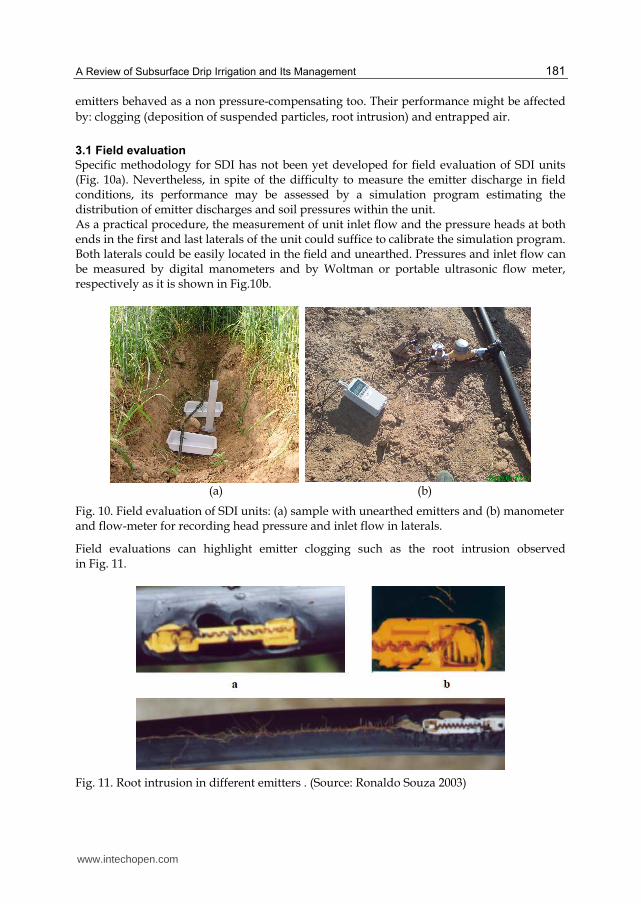
3.1 Field evaluation
Specific methodology for SDI has not been yet developed for field evaluation of SDI units (Fig. 10a). Nevertheless, in spite of the difficulty to measure the emitter discharge in field conditions, its performance may be assessed by a simulation program estimating the distribution of emitter discharges and soil pressures within the unit. As a practical procedure, the measurement of unit inlet flow and the pressure heads at both ends in the first and last laterals of the unit could suffice to calibrate the simulation program. Both laterals could be easily located in the field and unearthed. Pressures and inlet flow can be measured by digital manometers and by Woltman or portable ultrasonic flow meter, respectively as it is shown in Fig.10b.
(a) (b)
Fig. 10. Field evaluation of SDI units: (a) sample with unearthed emitters and (b) manometer and flow-meter for recording head pressure and inlet flow in laterals.
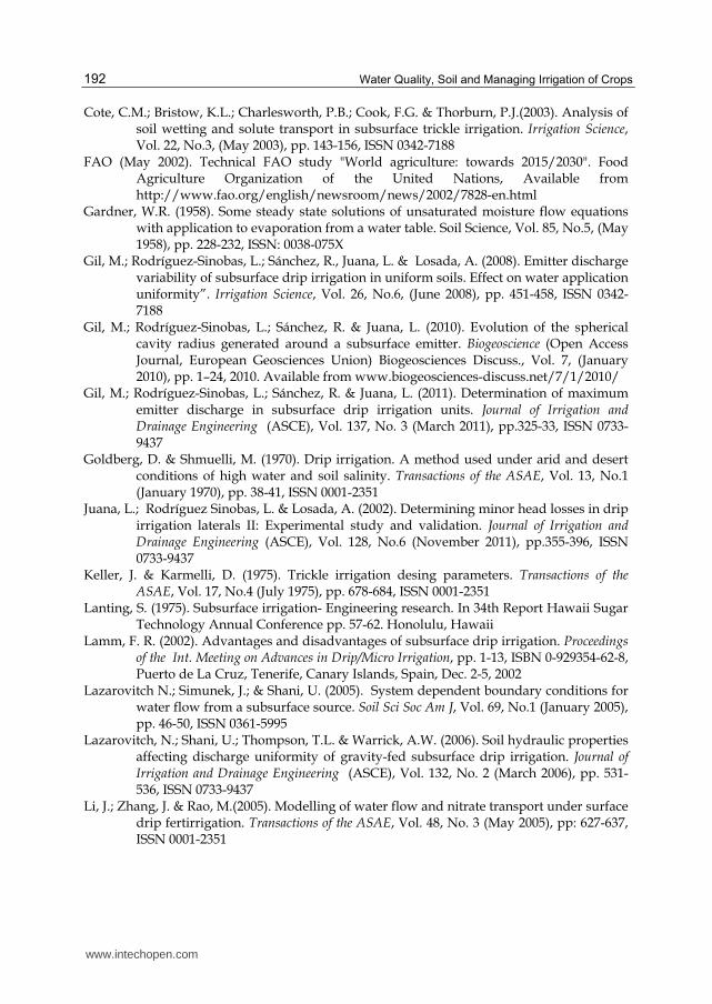
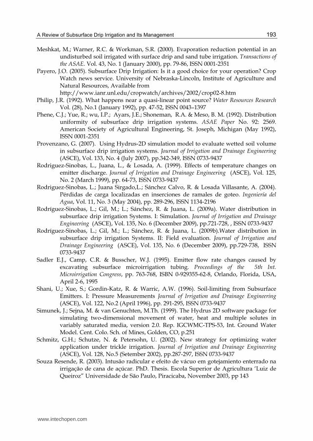
Field evaluations can highlight emitter clogging such as the root intrusion observed in Fig. 11.
Fig. 11. Root intrusion in different emitters . (Source: Ronaldo Souza 2003)
www.intechopen.com

Water Quality, Soil and Managing Irrigation of Crops
182
4. Simulating subsurface drip irrigation
As it was mentioned above, simulations are a tool for estimating the performance of laterals
and units. On the one hand, discharges and pressures of the emitters among the unit
(generally looped units) can be computed taking into account the soil properties. On the
other hand, the movement of water in the soil and wet bulb geometry can also be estimated.
4.1 Simulation of subsurface drip irrigation laterals and units
A computer program can be developed to predict water distribution along SDI laterals and
units. To do so, we would need to take into account:
Design variables: length and diameters of laterals; submain and flushing pipe; emitter
discharge; emitter’s manufacture and wear coefficient and local losses at the insertions
of the emitters and the laterals.
Operation variables: inlet pressure and irrigation time.
Soil properties: at least texture and saturated hydraulic conductivity and if possible, the
other soil parameters of Eq. [2]. When dealing with spatial variability, it is required the
couple of a specific geo-statistical modelling software and the one predicting water
distribution within the unit.
Thus for a target irrigation uniformity, different study cases can be simulated and then, the
selection of proper values for the design or operation variables could be achieved.
Moreover, the suitability of this method to different soil types and their best management
practices can be addressed prior the unit is laid on in the field.
4.1.1 Hydraulic calculation of laterals
In this chapter, we present a simulation program developed by Rodríguez-Sinobas el al.
2009a which calculates the flow rates for surface emitters in laterals with Eq. [3] and for
buried emitters with Eq. [4]. The overpressure hs at the emitter exit was obtained with Eq.
[2]. Likewise, the head pressure at each emitter insertion hi was determined by application
of the energy equation as follows:
1 1 0i i i ih h hf I s (7)
where hfi-i+1 is the head loss between two consecutive emitters i-i+1; I0 is the lateral slope
and s is the emitter spacing.
Flow regime in laterals is considered smooth turbulent with Reynolds numbers within the
range 3000 < R < 100 000 since most subsurface drip irrigation laterals are made of smooth
polyethylene pipe. Thus Blasius’ head loss equation provides an accurate estimation of the
frictional losses inside uniform pipes. Likewise, local head losses at emitter insertions are
included as an equivalent length le. Then head loss hfi-i+1 between two successive emitters i-
i+1 can be calculated as
1.75
0.25 11 4.75
0.0246 · · 1i i ei i
Q lhf s
sD (8)
where Qi-i+1 is the flow conveying in the uniform pipe between emitters i-i+1; D is the lateral
internal diameter and the kinematic water viscosity.
www.intechopen.com

A Review of Subsurface Drip Irrigation and Its Management
183
In most commercial models, local head losses at the emitter insertion are within the interval of 0.2 and 0.5 m (Juana et al. 2002). Lateral head losses hf can be calculated as
1.75
0.25 04.75
0.0246 · · 1 eQ lhf F L
sD (9)
where Q0 is the lateral inlet flow; L is the lateral length and F the reduction factor. The reduction factor F (Christiansen 1942) takes the form
2
1 1 1
1 2 6
mF
m N N
(10)
where N is the number of emitters and m is the flow exponent of the head loss equation. This formula applied to laterals with the first emitter located at a distant L/N from the inlet. In general, number of emitters in laterals is large, and water distribution is assumed to be continuous and uniform. Hence, F= 1/(1+m). As said, emitter discharge in SDI can be affected by soil properties. It can be influenced by
Ks and , each of them varying throughout the field. Furthermore, the discharge can be also affected by variation in cavity radius r0. Soil hydraulic properties from close points are expected to be more alike than those far apart, they can be correlated using variograms. Furthermore, these can aim at the estimation of soil properties distribution.
Examples
For the porpoise of illustration, the performance of a lateral in different uniform soils is represented in Fig. 12a, and the effect of soil heterogeneity is shown in Fig.12b. The comparison of the performance between SDI and surface laterals is addressed in all the examples. The uniformity index CVq is higher in SDI than in the surface drip irrigation in all uniform
soils except for the sandy one, where uniformities are alike. For a given r0 and h0, the
possible self-regulation due to the interaction between the emitter discharge and soil
pressure is observed in low saturated hydraulic conductivity soils (loamy and clay). The
larger the cavity radio the smaller the soil effect, and thus, the SDI lateral behaves as a
surface lateral. The irrigation uniformity index in non-uniform soils is less than in uniform
soils. It slightly reduces as r0 and h0 decrease.
For sandy soils the uniformity is very similar in both laterals; even the uniformity in the SDI
lateral is higher for certain values of r0 and h0.
In loamy soils, for higher r0 values, the uniformity reduces as emitter flow increases.
However, with small r0 this trend is not shown, and similar uniformities are observed
between the smaller emitter flows. The larger the cavity the smaller the soil effect, and thus
the SDI lateral would behave as a surface lateral. No difference in water application
uniformity is observed between surface and buried laterals in loamy soils for values of r0 >
0.01 m. On the contrary, for small r0 the self-regulating effect is predominant. Therefore, this
is enhanced by higher emitter flows since they develop higher soil overpressures.
For heterogeneous loamy soils the tendency is similar to the homogeneous soil: irrigation
uniformity decreases as emitter discharge increases (Fig. 12b). However in some scenarios,
the values of CVq are higher. The uniformity is similar in all the three discharges for r0 >
0.01; below this value, uniformity rapidly decreases.
www.intechopen.com

Water Quality, Soil and Managing Irrigation of Crops
184
Note: Units for r0 and h0 are expressed in m.
Fig. 12. Irrigation uniformity index CVq as a function of r0 and h0 in different soils for a SDI lateral with non-compensating emitters: (a) uniform soils; (b) non-uniform soils.
Uniformity of water application in all cases reduces as inlet pressure increases.
Consequently, it would be advisable to select emitters with small discharge, and to irrigate
with inlet pressure not very small (in this case above 10 m).
4.1.2 Hydraulic calculation of units
Typical SDI units are composed of a looped network (Fig. 2). Water can move either way
from head to downstream lateral and reverse. The hydraulic calculation of laterals can be
achieved as it was outlined in section 4.1.1. The inlet pressure h0 at each lateral would be
determined as
0 0 1 1 0i i Si i S Lh h hf I s (11)
www.intechopen.com

A Review of Subsurface Drip Irrigation and Its Management
185
where i and i+1 are sub-indices for two successive laterals; hfSi-i+1 are the head loss in the uniform pipe between laterals i-i+1; I0S is the submain slope and sL is the lateral spacing. hfSi-i+1 may be determined with Eq. [8] considering the flow conveying between the laterals i and i+1. Each lateral inflow can be calculated by adding the flow from all of its emitters. Local head losses at the connection of the lateral with the submain are smaller than those in laterals (Rodriguez-Sinobas et al. 2004), and could be left out in Eq. [8]. Two conditions are met for calculation of looped network. First, the sum of flows conveying along the submain equates the sum of the emitter’s flow throughout the unit. Second, the pressure at every location within the network is the same when calculated from head towards the downstream end of the lateral than reversed. The direction of flow in a loop network is not known. A minimum energy line with minimum pressures divides the flow coming from the lateral head and the one coming from its downstream end. Thus from this line, the network calculation is accomplished as two branched networks: one whose length corresponded to the distance from the lateral inlet up to energy line; and the other whose length corresponded to the distance from the downstream end of the lateral to that line This program predicts discharges and pressures from both directions. The iterative process stops when minimum pressures are met. If the value for minimum pressure from one way is larger than from the other, the energy line moves towards the least pressure. Likewise, the sum of the flows coming and exiting from the flushing pipe is zero. The program ouputs are: the flows and pressures at the inlet and downstream end of the laterals; the minimum energy line; the distribution of emitter discharges and emitter pressures; and the irrigation uniformity coefficient CVq. Simulations can be performed for irrigation units both laid on the surface and buried in the soil. In the last, emitter discharge is calculated with Eq. [4] and soil water pressure at the emitter outlet is calculated with Eq. (2). Soil variability may be determined as detailed for laterals but in this case, the variable will be two-dimensional.
Example
A looped unit operating at several pressures in a loamy soil is selected for illustration of the performance of a typical SDI unit in Fig.13. For all cases, irrigation uniformity improves with small emitter discharges. In non-uniform soils, the irrigation uniformity indexes are higher than in uniform soils, but their differences were small. Only the clay soil with the highest discharge displayed a significant difference. In summary, irrigation uniformity is very good for most of the typical selected scenarios. Nevertheless, for clay soils emitter discharge reduced 14 % and this should be taken into account in the management of the irrigation system. On the other hand, if higher emitter flows would have been selected, the unit would have performed worse.
4.2 Hydrus 2D/3D
The program HYDRUS-2D/3D (Simunek et al. 1999) includes computational finite element models for simulating the two- and three-dimensional movement of water, heat, and multiple solutes in variably saturated media. Thus it can simulate the transient infiltration process by numerically solving Richards’ equation. The program is recommended as a useful tool for research and design of SDI systems. This simulation program may be used for optimal management of SDI systems (Meshkat et al.
www.intechopen.com

Water Quality, Soil and Managing Irrigation of Crops
186
2000; Schmitz et al. 2002; Cote et al. 2003; Li et al. 2005) or for system design purposes (Ben-Gal et al. 2004; Provenzano 2007; Gil et al 2011).
Note: Units for r0 and h0 are expressed in m.
Fig. 13. Irrigation uniformity coefficient CVq as a function of r0 and h0 in a SDI lateral with non-compensating emitters of different discharges: (a) loamy uniform soil; (b) loamy non-uniform soil.
To simulate water movement in SDI emitters, a two-dimensional axis-symmetric water flow around a spherical surface may be simulated reproducing the hydraulic conditions. Simulations can considered a one-half cross section the soil profile. A sphere with a radius r0 can be placed at a given depth below the soil surface, simulating the emitter and the cavity formed around a subsurface source. A triangular mesh is automatically generated by the program. Dimensions of the finite-elements grid (triangles) may be refined around the emitter and other key points. Boundary conditions can be selected as follows: absence of flux across central axis and the opposite side; the atmospheric condition on the soil surface and free drainage along the bottom of soil profile. For compensating emitters, a constant flux boundary may be assumed around the
www.intechopen.com

A Review of Subsurface Drip Irrigation and Its Management
187
cavity—it corresponded to the emitter discharge. For non compensating emitters, a variable flux boundary condition, function of the soil-water pressure, could be assumed calculated from the x and k coefficients of the emitter discharge equation.
Examples
Fig. 14. Geometry, mesh and boundary conditions.
Fig. 15. Example of water distribution in a sandy soil after 4 h of irrigation (q = 10 L/h).
5. Criteria for the design and management of subsurface drip irrigation
In designing SDI systems variables such as emitter discharge, lateral depth and emitter spacing must be selected. Likewise, the management of these systems includes the selection of the operating pressure and the irrigation time. The inlet pressure in the irrigation unit determines the uniformity of water application whereas the irrigation time is a key factor to meet crop water and nutrient requirements
www.intechopen.com

Water Quality, Soil and Managing Irrigation of Crops
188
5.1 Determination of maximum emitter discharge Since soil properties may reduce emitter discharge, the maximum emitter flow rate can be selected by a method called ‘soil pits method’ (Battam et al. 2003). A steady water flow is introduced to the soil through a narrow polyethyene tube that is located underneath the soil, during a given time. The depth at which no surfacing occurs is taken as the minimum depth for SDI laterals. Other method proposed by Gil et al. (2011) is based on the following dimensionless emitter discharge equation:
* ( *)xq k h (12)
with q*= q/h0x and h*=(h0 -hs)/h0; where h0 is the emitter pressure. Values of pressure-discharge from several emitter compensating and non-compensating models, arranged according eq. [12], show the same trend. Each category follows, approximately, a single line that shows a linear relationship in flow rate variation below 50 %( see Fig.16).
Fig. 16. Variation of q* (q/h0x ) versus h* [(h0 -hs)/h0] for different emitter models. (Source: Gil el al. 2011).
From the above graph, a target uniformity for SDI design is selected and then, h* calculated. Considering a typical variation of q*= 10%, h*= 0.79 and 0.05 for non- compensating and compensating emitters, respectively. Then, the overpressure generated in the soilhs can be calculated from Eq. [12] for different h0 values. These would correspond to emitter pressures within the lateral to limit the reduction of emitter discharge to 10 %. However, the performance of pressure compensating emitters differs from the non-compensating. In theory, their flow rate keeps constant within their compensating interval but for other values, these would be affected by soil pressure. Thus, considering an emitter head h0= 10 m and h* = 0.05, h0 -hs = 0.5 m. For anti-drain emitters, this value would not be reached since once the pressure gradient is less than 2 m, the emitter would close its discharging orifice.
www.intechopen.com

A Review of Subsurface Drip Irrigation and Its Management
189
Once the valuehs is known, emitter flow rate could be calculated from its relation with q as the one depicted in Fig. 17. This relation depends upon soil hydraulic properties and it could be determined by numerical models simulating soil water movement. The maximum discharge qmax will be obtained by adding to the assigned value the discharge emitter variation desired (10% in the given example).
Fig. 17. Relation betweenhs andq for different soils considering a constant spherical radius r0. (Source: Gil el al. 2011).
5.2 Design and management of subsurface drip irrigation
Computer programs developed for the hydraulic characterization and prediction of water distribution in SDI units have been proved as a useful tool for the design and management of SDI systems under specific scenarios. In addition, these programs might be coupled with geostatistical modelling software for the inclusion of spatial distribution of soil variability. Results show that SDI irrigation is suitable for sandy soils and is also suitable for loamy soils under specific conditions. It is advisable to select emitters with small discharge (1 L/h and 2 L/h), and to irrigate with inlet pressures not very small. The uniformity of water application index CVq in non-uniform soils is less than in uniform soils (Fig. 13). It is higher in SDI than in the surface drip irrigation in all uniform soils except for the sandy one, where both uniformities are alike. On the other hand, the wetted bulb dimensions and its water distribution are two main factors determining emitter spacing and lateral depth. Both variables are selected in order to obtain an optimum water distribution within the crop root zone. The depth of wetting bulb coincides with the length of the plant roots. As an illustration, some guidelines for the project and management of SDI units in a uniform loamy soil are introduced to highlight the applicability of finite element models for simulating water movement in SDI. The example simulates a line source that would correspond to water movement in laterals with small emitter spacing. Thus, the wetted area follows a continuous line with variable width. Two irrigation times and three possible
www.intechopen.com

Water Quality, Soil and Managing Irrigation of Crops
190
lateral depths are compared considering an emitter pressure of 16 m and a uniform initial water content of 0.1 m3/m3. Fig. 18 shows that for this scenario, emitter depths deeper than 10 cm are recommended to prevent soil surface wetting for irrigation times higher than 30 min. Differences observed for 0.2 and 0.3 m depths were negligible.
Fig. 18. Wetting bulbs of drip and a SDI in uniform loamy soil for an emitter pressure of 16
m and initial soil water content 0= 0.1 .
Wetting bulbs could be simulated for different scenarios by numerical methods such as
Hydrus-2D. For each soil, selection of proper design variables (emitter spacing or lateral
depth) and/or operation variables (inlet head and irrigation time) could be guided by
figures, as those shown above, or by graphs showing wetting bulb dimensions for different
conditions.
6. Perspectives for subsurface drip irrigation
Irrigation will be one key factor to sustain food supply for the world increasing population. The technical FAO study "World agriculture: towards 2015/2030” (FAO 2002) highlights that production of staple crops must follow the same increasing trend than in the last decades. Therefore, their productivity should rise and, thus irrigation will play an important role but it will have to adjust to the conditions of water scarcity and environmental and ecological sustainability.
www.intechopen.com

A Review of Subsurface Drip Irrigation and Its Management
191
On the other hand, many areas in the world, as their economy develops, the urban activities expand increasing water demands and develop competing uses of limited water resources. Thus, it raises uncertainty whether the volume of water used in irrigated agriculture can be sustained. Within this framework, water conservation policies are developed by policymakers reinforcing the use of new technologies and more efficient irrigation methods. Farmers are encouraged to use irrigation methods that reduce water use and increase yield in order to allow water to flow to other economic sectors. In consequence, subsurface drip irrigation perspectives are promising. It shows higher capability for minimizing the loss of water by evaporation, runoff, and deep percolation in comparison to other methods. Thus, the irrigation water saved may become available for other uses. It may also lead to increase crop yields since it reduces fluctuations in soil water content and well aerated plan root zone. In addition, treated wastewaters could be used with risk reduction in human and animal health in arid areas with water scarcity. Moreover, it may reduce agrochemical application since agrochemicals are precisely distributed within the active roots zone. Finally, SDI efficiency, in some scenarios, is better than surface trickle irrigation, and it requires smaller inlet heads. Thus energy savings are also enhanced. Furthermore, SDI may eliminate anaerobic decomposition of plant materials and thus substantially reduce methane gas production.
7. Acknowledgment
We would like to thank the Spanish Ministry of Science and Technology (CICYT) for its support provided through project No. AGL2008-00153/AGR.
8. References
American Society of Agricultural Engineering (ASAE). (2005). ASAE standards engineering practices data. 43rd edition: 864. Michigan. (August 2005), ISBN 1892769476
American Society of Agricultural Engineering (ASAE). (2003). Design and installation of microirrigation systems. Standard EP-405.1, (February 2003), ISSN 0032-0889
Ayars, J.E., Schoneman, R.A., Dale, F., Meson, B. & Shouse, P. (2001). Managing subsurface drip irrigation in the presence of shallow ground water. Agricultural Water Managenemt., Vol. 47, No.3, ( April 2001), pp. 242-264, ISSN 0378-3774
Bainbridge, A. (2001). Buried clay pot irrigation: a little known but very efficient traditional method of irrigation. Agricultural Water Management, Vol. 48, No.2, (June 2001), pp. 79-88, ISSN 0378-3774
Batam, M.A., Sutton, B.G. & Boughton, D.G. (2003). Soil pit as a simple design aid for subsurface drip irrigation systems. Irrigation Science, Vol. 22, No. 3/46, (October 2003), pp. 135-141, ISSN 0342-7188
Bralts, V.F., Wu,I.P. & Gitlin, H.M. (1981). Manufacturing variation and drip irrigation uniformity. Transactions of the ASAE Vol. 24, No. 1, (January 1981) pp. 113-119, ISSN 0001-2351
Ben-Gal A., Lazorovitch, N. & Shani, U. (2004). Subsurface drip irrigation in gravel filled cavities. Vadose Zone Journal Vol. 3, pp. 1407-1413
Christiansen , J.E. (1942). Irrigation by sprinkling. University of California Agriculture Experiment Station Bulletin, 670
www.intechopen.com
Water Quality, Soil and Managing Irrigation of Crops
192
Cote, C.M.; Bristow, K.L.; Charlesworth, P.B.; Cook, F.G. & Thorburn, P.J.(2003). Analysis of soil wetting and solute transport in subsurface trickle irrigation. Irrigation Science, Vol. 22, No.3, (May 2003), pp. 143-156, ISSN 0342-7188
FAO (May 2002). Technical FAO study "World agriculture: towards 2015/2030". Food Agriculture Organization of the United Nations, Available from http://www.fao.org/english/newsroom/news/2002/7828-en.html
Gardner, W.R. (1958). Some steady state solutions of unsaturated moisture flow equations with application to evaporation from a water table. Soil Science, Vol. 85, No.5, (May 1958), pp. 228-232, ISSN: 0038-075X
Gil, M.; Rodríguez-Sinobas, L.; Sánchez, R., Juana, L. & Losada, A. (2008). Emitter discharge variability of subsurface drip irrigation in uniform soils. Effect on water application uniformity”. Irrigation Science, Vol. 26, No.6, (June 2008), pp. 451-458, ISSN 0342-7188
Gil, M.; Rodríguez-Sinobas, L.; Sánchez, R. & Juana, L. (2010). Evolution of the spherical cavity radius generated around a subsurface emitter. Biogeoscience (Open Access Journal, European Geosciences Union) Biogeosciences Discuss., Vol. 7, (January 2010), pp. 1–24, 2010. Available from www.biogeosciences-discuss.net/7/1/2010/
Gil, M.; Rodríguez-Sinobas, L.; Sánchez, R. & Juana, L. (2011). Determination of maximum emitter discharge in subsurface drip irrigation units. Journal of Irrigation and Drainage Engineering (ASCE), Vol. 137, No. 3 (March 2011), pp.325-33, ISSN 0733-9437
Goldberg, D. & Shmuelli, M. (1970). Drip irrigation. A method used under arid and desert conditions of high water and soil salinity. Transactions of the ASAE, Vol. 13, No.1 (January 1970), pp. 38-41, ISSN 0001-2351
Juana, L.; Rodríguez Sinobas, L. & Losada, A. (2002). Determining minor head losses in drip irrigation laterals II: Experimental study and validation. Journal of Irrigation and Drainage Engineering (ASCE), Vol. 128, No.6 (November 2011), pp.355-396, ISSN 0733-9437
Keller, J. & Karmelli, D. (1975). Trickle irrigation desing parameters. Transactions of the ASAE, Vol. 17, No.4 (July 1975), pp. 678-684, ISSN 0001-2351
Lanting, S. (1975). Subsurface irrigation- Engineering research. In 34th Report Hawaii Sugar Technology Annual Conference pp. 57-62. Honolulu, Hawaii
Lamm, F. R. (2002). Advantages and disadvantages of subsurface drip irrigation. Proceedings of the Int. Meeting on Advances in Drip/Micro Irrigation, pp. 1-13, ISBN 0-929354-62-8, Puerto de La Cruz, Tenerife, Canary Islands, Spain, Dec. 2-5, 2002
Lazarovitch N.; Simunek, J.; & Shani, U. (2005). System dependent boundary conditions for water flow from a subsurface source. Soil Sci Soc Am J, Vol. 69, No.1 (January 2005), pp. 46-50, ISSN 0361-5995
Lazarovitch, N.; Shani, U.; Thompson, T.L. & Warrick, A.W. (2006). Soil hydraulic properties affecting discharge uniformity of gravity-fed subsurface drip irrigation. Journal of Irrigation and Drainage Engineering (ASCE), Vol. 132, No. 2 (March 2006), pp. 531-536, ISSN 0733-9437
Li, J.; Zhang, J. & Rao, M.(2005). Modelling of water flow and nitrate transport under surface drip fertirrigation. Transactions of the ASAE, Vol. 48, No. 3 (May 2005), pp: 627-637, ISSN 0001-2351
www.intechopen.com
A Review of Subsurface Drip Irrigation and Its Management
193
Meshkat, M.; Warner, R.C. & Workman, S.R. (2000). Evaporation reduction potential in an undisturbed soil irrigated with surface drip and sand tube irrigation. Transactions of the ASAE. Vol. 43, No. 1 (January 2000), pp. 79-86, ISSN 0001-2351
Payero, J.O. (2005). Subsurface Drip Irrigation: Is it a good choice for your operation? Crop Watch news service. University of Nebraska-Lincoln, Institute of Agriculture and Natural Resources, Available from
http://www.ianr.unl.edu/cropwatch/archives/2002/crop02-8.htm Philip, J.R. (1992). What happens near a quasi-linear point source? Water Resources Research
Vol. (28), No.1 (January 1992), pp. 47-52, ISSN 0043–1397 Phene, C.J.; Yue, R.; wu, I.P.; Ayars, J.E.; Shoneman, R.A. & Meso, B. M. (1992). Distribution
uniformity of subsurface drip irrigation systems. ASAE Paper No. 92: 2569. American Society of Agricultural Engineering, St. Joseph, Michigan (May 1992), ISSN 0001-2351
Provenzano, G. (2007). Using Hydrus-2D simulation model to evaluate wetted soil volume in subsurface drip irrigation systems. Journal of Irrigation and Drainage Engineering (ASCE), Vol. 133, No. 4 (July 2007), pp.342-349, ISSN 0733-9437
Rodriguez-Sinobas, L., Juana, L., & Losada, A. (1999). Effects of temperature changes on emitter discharge. Journal of Irrigation and Drainage Engineering (ASCE), Vol. 125, No. 2 (March 1999), pp. 64-73, ISSN 0733-9437
Rodriguez-Sinobas, L.; Juana Sirgado,L.; Sánchez Calvo, R. & Losada Villasante, A. (2004). Pérdidas de carga localizadas en inserciones de ramales de goteo. Ingeniería del Agua, Vol. 11, No. 3 (May 2004), pp. 289-296, ISSN 1134-2196
Rodríguez-Sinobas, L.; Gil, M.; L.; Sánchez, R. & Juana, L. (2009a). Water distribution in subsurface drip irrigation Systems. I: Simulation. Journal of Irrigation and Drainage Engineering (ASCE), Vol. 135, No. 6 (December 2009), pp.721-728, , ISSN 0733-9437
Rodríguez-Sinobas, L.; Gil, M.; L.; Sánchez, R. & Juana, L. (2009b).Water distribution in subsurface drip irrigation Systems. II: Field evaluation. Journal of Irrigation and Drainage Engineering (ASCE), Vol. 135, No. 6 (December 2009), pp.729-738, ISSN 0733-9437
Sadler E.J., Camp, C.R. & Busscher, W.J. (1995). Emitter flow rate changes caused by excavating subsurface microirrigation tubing. Proceedings of the 5th Int. Microirrigation Congress, pp. 763-768, ISBN 0-929355-62-8, Orlando, Florida, USA, April 2-6, 1995
Shani, U.; Xue, S.; Gordin-Katz, R. & Warric, A.W. (1996). Soil-limiting from Subsurface Emitters. I: Pressure Measurements Journal of Irrigation and Drainage Engineering (ASCE), Vol. 122, No.2 (April 1996), pp. 291-295, ISSN 0733-9437
Simunek, J.; Sejna, M. & van Genuchten, M.Th. (1999). The Hydrus 2D software package for simulating two-dimensional movement of water, heat and multiple solutes in variably saturated media, version 2.0. Rep. IGCWMC-TPS-53, Int. Ground Water Model. Cent. Colo. Sch. of Mines, Golden, CO, p.251
Schmitz, G.H.; Schutze, N. & Petersohn, U. (2002). New strategy for optimizing water application under trickle irrigation. Journal of Irrigation and Drainage Engineering (ASCE), Vol. 128, No.5 (Setember 2002), pp.287-297, ISSN 0733-9437
Souza Resende, R. (2003). Intusão radicular e efeito de vácuo em gotejamiento enterrado na irrigação de cana de açúcar. PhD. Thesis. Escola Superior de Agricultura ‘Luiz de Queiroz” Universidade de São Paulo, Piracicaba, November 2003, pp 143
www.intechopen.com

Water Quality, Soil and Managing Irrigation of Crops
194
United State Deparment of Agriculture USDA-NASS. (2009). Farm and Ranch Irrigation Survey National Agricultural Statistic Service, Available from www.nass.usda.gov
Vaziri, C.M. & Gibson, W. (1972). Subsurface and drip irrigation for Hawaiian sugarcane. In: 31st Report Hawaii Sugar Technology Annual Conference, Honolulu, 1972. Proceedings. Honolulu: Hawaiian sugar Planters Assoc., 1972, pp.18-22
www.intechopen.com

Water Quality, Soil and Managing Irrigation of CropsEdited by Dr. Teang Shui Lee
ISBN 978-953-51-0426-1Hard cover, 242 pagesPublisher InTechPublished online 28, March, 2012Published in print edition March, 2012
InTech EuropeUniversity Campus STeP Ri Slavka Krautzeka 83/A 51000 Rijeka, Croatia Phone: +385 (51) 770 447 Fax: +385 (51) 686 166www.intechopen.com
InTech ChinaUnit 405, Office Block, Hotel Equatorial Shanghai No.65, Yan An Road (West), Shanghai, 200040, China
Phone: +86-21-62489820 Fax: +86-21-62489821
The book entitled Water Quality, Soil and Managing Irrigation of Crops comprises three sections, specifically:Reuse Water Quality, Soil and Pollution which comprises five technical chapters, Managing Irrigation of Cropswith four, and Examples of Irrigation Systems three technical chapters, all presented by the respective authorsin their own fields of expertise. This text should be of interest to those who are interested in the safe reuse ofwater for irrigation purposes in terms of effluent quality and quality of urban drainage basins, as well as tothose who are involved with research into the problems of soils in relation to pollution and health, infiltrationand effects of irrigation and managing irrigation systems including basin type of irrigation, as well as thesubsurface method of irrigation. The many examples are indeed a semblance of real world irrigation practicesof general interest to practitioners, more so when the venues of these projects illustrated cover a fair range ofclimate environments.
How to referenceIn order to correctly reference this scholarly work, feel free to copy and paste the following:
Leonor Rodríguez Sinobas and María Gil Rodríguez (2012). A Review of Subsurface Drip Irrigation and ItsManagement, Water Quality, Soil and Managing Irrigation of Crops, Dr. Teang Shui Lee (Ed.), ISBN: 978-953-51-0426-1, InTech, Available from: http://www.intechopen.com/books/water-quality-soil-and-managing-irrigation-of-crops/a-review-of-subsurface-drip-irrigation-and-its-management

© 2012 The Author(s). Licensee IntechOpen. This is an open access articledistributed under the terms of the Creative Commons Attribution 3.0License, which permits unrestricted use, distribution, and reproduction inany medium, provided the original work is properly cited.