a review of the geothermal reservoir well stimulation program
TRANSCRIPT
A REVIEW OF THE GEOTHERMAL RESERVOIR WELL STIMULATION PROGRAM
0. A. Campbell . A. R. Slnclalr
R.lJ. Hanold 0. J. Vstter Republic Geothermal, Inc.
Los Alamos National. Laboratory
Maurer Englneering, Inc.
Vetter Research
u
United S ta tes
ABSTRACT
Republic Geothermal, Inc., and s subcontractors have planned and executed four experimental fjracture stimulation treatments under the Department of Energy-funded Geothermal Reservoir Well Stimulation Program (GRWSP). The 2-year program, begun in February 1979, is Ulti- mately to include six full-scale field hydraulic and chemical stimula- tion experiments in geothermal wells. This paper describes the over- all program and the four treatments completed to date.
The GRWSP is organized into two phases. Phase I consists of litera- ture and theoretical studies, laboratory investigations, and numerical work. The main purpose of this work is to establish the technological bases for geothermal well stirnulation design. Phase I1 will include the planning, execution, and evaluation of six well stimulation treat-
.- which utilize the technology developed in Phase I.
Two stimulation experiments were performed at the Raft River, Idaho, known geothermal resource area (KGRA) in late 1979. This is a natu- rally fractured, hard rock reservoir with a relatively low geothermal resource temperature 149"Ck (300"F*). A conventional planar hydraulic fracture job was performed in Well RRGP-5 and a "Kiel" dendritic, or reverse flow, technique was utilized in Well RRGP-4.
In mid-1980, two stimulation experiments were performed at the East Mesa, California, KGRA. The stimulation of Well 58-30 provided the first geothermal well fracturing experience in a moderate temperature, 177"C* (350"F*), reservoir with matrix-type rock properties. The two treatments consisted of a conventional hydraulic fracture of a deep, low-permeability zone and a mini-frac "Kiel" treatment of a shallow, high-permeability zone in the same well.
The stimulation experiment results to date were evaluated using short-term production tests, conventional pressure transient analysis, interference pressure data, chemical' and radioactive tracers, borehole acoustic televiewer surveys and numerical models. This combination Of evaluation techniques yielded an interpretation of fracture geometry and productivity enhancement. However, the evaluation of artificially induced fractures in naturally fractured formations was found to lead to possibly non-unique solutions.
In all the field experiments, artificial fractures were created and well productivity was increased. A discussion of the prestimulation and poststimulation data and their evaluation are provided for each experiment in this report.
21-1

DISCLAIMER
This report was prepared as an account of work sponsored by an agency of the United States Government. Neither the United States Government nor any agency Thereof, nor any of their employees, makes any warranty, express or implied, or assumes any legal liability or responsibility for the accuracy, completeness, or usefulness of any information, apparatus, product, or process disclosed, or represents that its use would not infringe privately owned rights. Reference herein to any specific commercial product, process, or service by trade name, trademark, manufacturer, or otherwise does not necessarily constitute or imply its endorsement, recommendation, or favoring by the United States Government or any agency thereof. The views and opinions of authors expressed herein do not necessarily state or reflect those of the United States Government or any agency thereof.

DISCLAIMER Portions of this document may be illegible in electronic image products. Images are produced from the best available original document.

I
INTRODUCTION
The stimulation of geothermal wells presents some new and i challenging problems. can be expected. The behavior of stimulation fluids, frac proppants, and equipment at these temperatures in a hostile brine environment must be carefully evaulated before performance expectations can be determined. horizon of the formation, high-temperature chemical compatibility between the in situ materials and the stimulation materials must be verified. Perhaps most significant of all, in geothermal wells the required techniques must be capable of bringing about the production of very large amounts of fluid. This necessity for high flow rates represents a significant departure from conventional petroleum well stimulation and demands the creation of very high near-wellbore permeability and/or fractures with very high flow conductivity.
produce either hot water or steam from both matrix permeability and from natural fracture systems. are of common interest in geothermal fields today:
Formation temperatures in the 300-600°F range
In order to avoid possible damage to the producing
Stimulation treatments may be conducted in formations which
The following targets of opportunity
. Wells that did not intersect nearby major fracture systems:
- . Wells that can benefit from the establishment of high conductivity linear flow channels to improve flow capacity from surrounding localized regions of low permeability formation:
. Wells that suffered man-made damage during drilling, completion, or workover operations, including mud or cement invasion: and
. Wells that require periodic remedial treatment as a result of fluid ,production related damage .
If stimulation can reduce or eliminate the need for new wells or redrills in these situations, then the potential for improving geothermal development economics and extending the resource base is substantial .
DOE PROGRAM
Recognition of the potential benefits of developing a successful geothermal well stimulation capability led the Department of Energy/Division of Geothermal Energy (DOE/DGE) to sponsor the
21-2

Geothermal Reservoir Well S 1979. The principal purpose of the discussion below is to review the
ulation Program (GRWSP) beginning in
bp)accomplishments to date and the current status of the program.
An organization chart for the program is shown on Figure 1. The DOE/DGE provides overall program management and funding with technical advice from L o s Alamos Scientific Laboratory (LASL). The prime contractor is Republic Geothermal, Inc. (RGI). Vetter Research (VR) is the principal. subcontractor dealing with the high pressure/temperature chemical aspects of the program and tracer studies. Petroleum Training and Technical Services (PTTS) is responsible for most of the mathematical modeling efforts. Maurer Engineering (MEI), the third major subcontractor, is responsible for some of the basic laboratory testing of material properties and the recommendation of frac fluids and proppants for dealing with the high temperature environment of geothermal wells. Maurer's main functions are, however, the study of the hydraulic fracture mechanics and fracture design for each experiment.
The program is divided into two phases. Phase I is basically the engineering and laboratory studies, and Phase I1 mostly covers the field experiments. Phase I is now nearly complete and four of the six planned experiments of Phase If have been done. The main Phase I tasks are summarized on Table 1. Assessment of the state-of- the-art was one of the two main objectives of Phase I, i.e., to - review the oil and gas industry stimulation technology and see how'it might be applied to geothermal wells, to determine what additional technology is needed, and to conduct laboratory and engineering work to both evaluate and fill the needs for that additional technology. The second principal objective was to provide the program with a sound technical base for Phase 11.
As shown on Table 2, the first Phase I1 task was to logically select and propose geothermal reservoirs and specific well candidates for stimulation experiments. The jobs were then to be planned, conducted, and evaluated. The first field experiment was to be a conventional hydraulic fracture treatment in a relatively low temperature geothermal reservoir. Thus, techniques on the margins of the upper temperature limit of what is currently being done in the oil and gas industry could be used. complexity of successive experiments was intended, along with the inclusion of a variety of lithologies. The scope of work was not to include explosives, and the emphasis was to be on hydraulic fracturing in hot water reservoirs. The last task of Phase I1 is to disseminate the results of the work with project reports and symposia.
Increasing the temperature and
21-3

A second symposium covering the program will be held in May 1981 to summarize all the results of work performed under the contract.
PROPPANTS
A significant portion of the Phase I laboratory investigation effort has been directed at finding suitable proppants for hydraulic fracture stimulation use. Although sand is generally used as a proppant today in the oil and gas industry, it has not proven to be strong enough to withstand the conditions in most geothermal wells. Sand is definitely affected by temperature, particularly when tested in hot water or brine under stress. Figure 2 shows the effect of temperature on common frac sand (20/40 mesh). These results are short-term results and only suggest the severity of long-term field results.
There are several mechanisms that can destroy sand grains in the fracture. First, the sand is brittle and point-to-point loading can cause brittle failure. Second, sand is full of microfractures and faults which weaken the sand. Finally, when sand is stressed in a corrosive medium like hot water, stress corrosion cracking appears to destroy the sand at low closure stresses. High temperatures and high stresses combine to bring out the worst properties of sand and tend to emphasize the fact that sand is inadequate as an effective proppant under high temperature conditions.
The strongest proppant tested to date is resin-coated bauxite. It shows no temperature sensitivity or permeability decrease under load. The resin-coated sand i s not temperature or load sensitive, but does have a slightly lower permeability at any closure stress due to a slightly different distribution of particle sizes. Figure 3 shows the permeability of resin-coated bauxite and resin-coated sand under varying closure stress to 10,000 psi at 350'F. No temperature sensitivities were found, so tests at all temperatures gave the same results shown in Figure 3 within experimental scatter. One important point is that the resin-coated materials are cohesive; therefore, once emplaced in the fracture, flowback is reduced during production. Although slightly crushable, sintered bauxite is much stronger than sand and effectively inert in hot brines. Figure 3 shows how sin- tered bauxite permeability behaves under increasing closure stress. Its permeability exceeds that of resin-coated sand at lower closure stress, but drops below that of resin-coated sand at 10,000 psi.
21-4

FLUIDS
Many fluids and fluid systems have been tested under Phase I for Watek. soluble polymers are the main vis- weotherma1 applications.
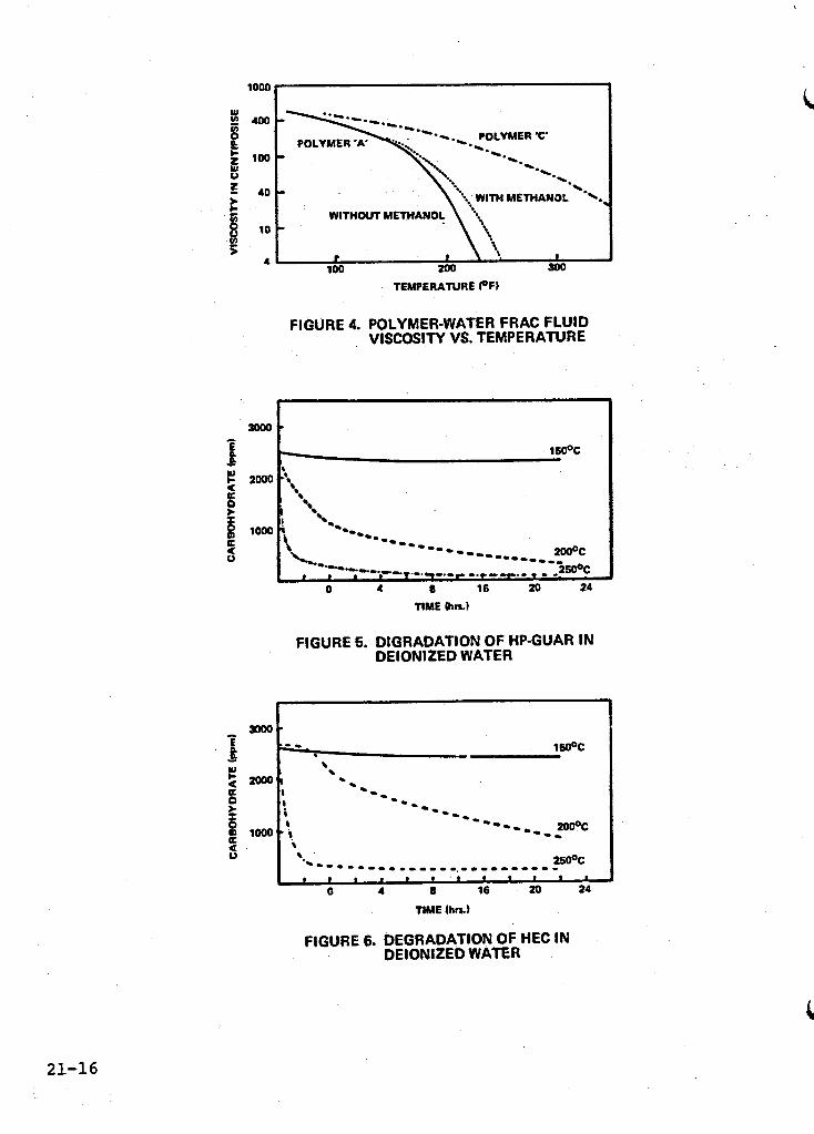
cosifiers for hydraulic fracturing. Above 250°F almost all polymer systems show a decline in viscosity. There are many techniques that can be used to delay this decline or degradation in properties. One such technique is the addition of a small amount of methanol to the polymer water solutions which has a stabilizing effect on the fluid. Other proprietary products are also available which can be added as high temperature stabilizers. Dissolved oxygen can cause polymer degradation, but by adding an oxygen scavenger to the water this- effect can be minimized. The effect of temperature on the viscosity of some proposed polymer-water frac fluid systems is illustrated in Figure 4. The rapid decline in viscosity of polymer "A" at temperatures above 200°F could result in poor proppant placement in a high-temperature geothermal stimulation treatment.
The type and amount of polymer determines the speed and extent of degradation. types, i.e., polysaccharides, modified celluloses and poly- acrylamides. These particular polymers are chosen because of their unique ability to viscosify water, and at the same time to reduce tubular friction and have a good tolerance to brine. In the case of geothermal wells, an ideal frac fluid would retain its desirable properties at the high temperature until it has done its job of placing the proppant in the fracture.
Polymers used in fracturing are of three basic
. I
A series of static aging tests have been performed to try to understand the degradation of these polymers and its relationship to viscosity, plugging, and exposure time'. Solutions mixed at 0.25 wt percent of polymer were aged in a stirred reaction vessel at 150, 200 and 250°C for 22 hours. Samples were taken from the vessels at 0, 0.5, 1.0, 3.0, 6.0, and 22.0 hours and analyzed. The samples were tested for carbohydrate content (CHO) and total organic carbon content (TOC), and w e r e then characterized w i t h h igh pressure l iqu id chromatography (HPLC) for molecular weight changes.
Typical results of these aging tests for two common frac polymers, uncrosslinked hydroxypropyl guar gum (HP Guar) and hydroxyethyl cellulose (HEC), are shown in Figures 5 and 6. These graphs show, as expected, that as the temperature is increased the polymer degrades to noncarbohydrate material. The HEC did not degrade significantly until after three hours at 200'C.
21-5

The uncrosslinked HP Guar, began to degrade to noncarbohydrate material immediately upon heating. Also, there was a corresponding.. drop in TOC content which coincided with the formation of particula$rd matter in the samples. Non-soluble carbonaceous material formed as the HP Guar was being heated to 200°C.
unchanged in molecular weight distribution after 22 hours at 15OoC, but does change to some extent at 200" and 250°C. The HP Guar changes to some extent at 150°C and then is changed dramatically at 200" and 250°C. These results report static test data which do not represent actual flow conditions that may be more severe.
Results from the HPLC showed that the HEC remains relatively
Flow tests in cores and sand packs have shown plugging tendencies from the degradation products of HP Guar at 150°C. This corresponds to the rapid change in molecular weight and drop in CHO and TOC resulting from the formation of non-soluble particulate matter from the HP Guar. Similar flow tests run with the HEC do not show a plugging tendency. On the other hand, experience has shown that it is very difficult to achieve predictable properties with HEC when mixed under typical field conditions. Crosslinking of HP Guar, which is now being tested in the laboratory, may offer the advantages of easy and reliable field handling coupled with temperature stability comparable to HEC.
These and other chemical tests can be of value in better defining the degradation of water-soluble polymers. They are useful not only for a fundamental understanding of frac fluid behavior, but help to select or reject fluids for specific applications. Moni- toring the produced fluid returns after an experiment for amount and level of degradation products may be quite important to help evaluate the job.
STIMULATION TREATMENTS AT RAFT RIVER
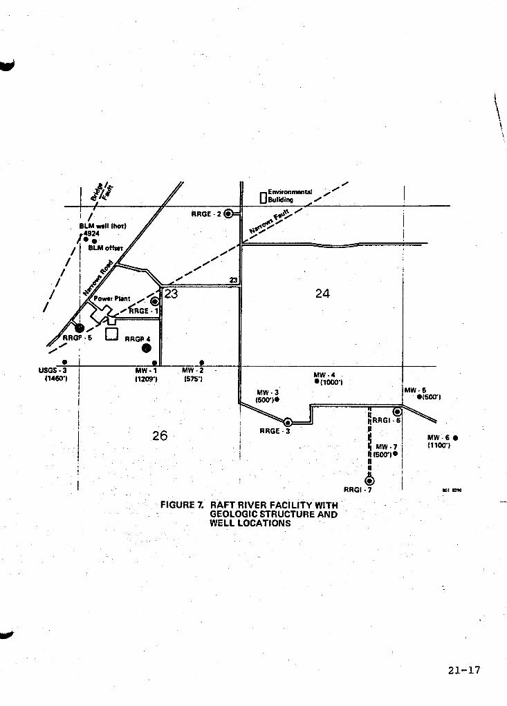
Raft River, Idaho, is a low-temperature (260-290°F) hydrothermal resource. Wells RRGE-1 and RRGE-2 (see Figure 7) are the best producing wells in the field and appear to intersect a natural fracture zone in the quartz monzonite reservoir. These fractures have high transmissibility, with a permeability-thickness (kh) of greater than 5 0 Darcy-feet. Wells RRGE-3, RRGP-4, and RRGP-5 are less productive and were all considered for stimulation. RRGP-4 and RRGP-5 were chosen as the best two candidates for stimulation because RRGE-3 is further from the best producing wells and its mechanical configuration is very complex. There are two major faults running through the field. The Narrows Fault lies between Wells RRGE-1 and RRGE-2, and trends roughly east-west. Well RRGP-4 is approximately 1/2 mile south of RRGE-1 and the Narrows Fault. The Bridge Fault is on the east side of the field and trends northeast-southwest. Well RRGP-5 lies between the two faults, near their intersection.
Wells
2i-6

Before stimulation, RRGP-4 was essentially non-productive. RRGP-5 , however, was capable of flowing at a stabilized rate of 140 spm and produced more than 600 gpm with a pump. This is adequate grs roductivity, but the production came from the upper portion of the completion interval, and the produced fluid temperature of 255°F was undesirably low. field and the proximity of Wells RRGP-4 and RRGP-5 to the Bridge and Narrows Faults, it was considered likely that highly productive fractures existed near the wells. Hydraulic fracture treatments in the deeper intervals were chosen as the best means to connect the wells with major productive fractures and to achieve the desired produced fluid temperatures of 270'F dr greater. Although on the upper temperature margins of conventional oil field fracturing technology, no special techniques or materials were thought to be necessary for Raft River.
Based on the performance of the better wells in the
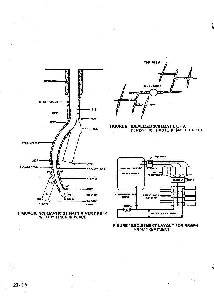
The mechanical configuration of Well RRGP-4 is shown in Figure 8. Because of rough hole conditions and the.perceived unreliability of available high temperature open-hole packers, it was necessary to cement a 7-inch liner in leg B. This shut off leg A and isolated a 195-foot.open-hole interval at the bottom of the well for hydraulic fracture treatment.
The technique employed was a four-stage dendritic fracture treatment. It was chosen because, if dendritic fracturing was achieved, it offered the best chance of intersecting major natural fractures. The main Concern was that a single, planar fracture might only parallel and not intersect the principal natural fractures. The main proponent of branched or dendritic fracturing has been Kiel. An estimated 750 Kiel fracs have been run to date. Dendritic fractures are caused by pulsing the formation with reverse flow which causes formation spalling and diversion of the fracture wings by downhole stress modification. Methods to predict the extent and direction of the fractures are still being worked upon: hewever, the best results have been reported in naturally fractured formations where major and minor fracture' systems already exist but may not have flow capability. Multiple pumping periods are used with each stage utilizing a low-viscosity fluid, sand slug88 and several flow-back periods. High flow rates and friction reduction are used in these treatments. An idealized schema a dendritic fracture system is depicted in Figure 9.
and utilize a light polymer gel frac fluid (HP Guar) carrying a relatively w concentration of proppant. The treatment included 50,400 Ibs of 100-mesh sand added for leak-off control and 58,000 lbs
The 7,900-barrel t tment was pumped a rate (50 bpm)
21-7
of 20-40 mesh sand proppant. Use of both sand and HP Guar was considered acceptable here because of the relativley low temperature,- The equipment layout for the frac treatment is shown in Figure 10.
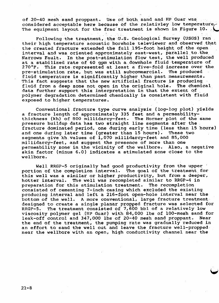
Following the treatment, the U.S. Geological Survey (USGS) ran their high temperature acoustic borehole televiewer and observed that the created fracture extended the full 195-foot height of the open interval and was oriented approximately east-west, parallel to the Narrows Fault. In the post-stimulation flow test, the well produced at a stabilized rate of 60 gpm with a downhole fluid temperature of 270OF. This rate represented at least a five-fold increase over the pre-stimulation rate, but was still subcommercial. The produced fluid temperature is significantly higher than past measurements. This fact suggests that the new artificial fracture is producing fluid from a deep zone not open in the original hole. data further support this interpretation in that the extent of polymer degradation determined chemically is consistent with fluid exposed to higher temperatures.
a fracture length of approximately 335 feet and a permeability- thickness (kh) of 800 millidarcy-feet. The Horner plot of the same pressure buildup data has two straight line segments after the fracture dominated period, one during early time (less than 15 hours) and one during later time (greater than 15 hours). segments give kh values of 1,070 millidarcy-feet and 85,000 millidarcy-feet, and suggest the presence of more than one permeability zone in the vicinity of the wellbore. Also, a negative skin factor (minus 6.0) indicates a stimulated zone close to the wellbore.
The chemical
Conventional fracture type curve analysis (log-log plot) yields
These two
Well RRGP-5 originally had good productivity from the upper '
portion of the completion interval. The goal of the treatment for this well was a similar or higher productivity, but from a deeper, hotter interval. The well was recompleted similar to RRGP-4 in preparation for this stimulation treatment. The recompletion consisted of cementing 7-inch casing which excluded the existing producing interval and left a 216-foot open-hole interval near the bottom of the well. A more conventional, large fracture treatment designed to create a single planar propped fracture was selected for RRGP-5. The treatment consisted of 7,600 bbl of a relatively low viscosity polymer gel (HP Guar) with 84,000 lbs of 100-mesh sand for leak-off control and 347,000 lbs of 20-40 mesh sand proppant. Near the end of the treatment, the pumping rate was gradually reduced in an effort to sand the well out and leave the fracture well-propped near the wellbore with an open, high conductivity channel near the
21-8

top. A s the rate approached zero, the wellhead pressure dropped to zero psig indicating that communication with the major natural 'acture system had been achieved, Also, a significant pressure sponse was noted in RRGE-1.
Following the treatment, the USGS borehole televiewer showed that the created fracture spanned the upper 135 feet of the open interval. The fracture was oriented nostheast-southwest, parallel to the Bridge Fault. In the post-stimulation production test, the well stabilized very rapidly at a 200 gpm rate with a 30 psia wellhead pressure. The produced fluid temperature was unchanged from the pre-stimulation flow. Following the natural flow test, a pump was installed in the well and it produced more than 650 gpn. Chemical analysis of the produced fluid indicated a relatively low rate of polymer degradation in the reservoir, confirming that the frac fluid traveled upward into a cooler portion of the reservoir.
the fracture treatment went upward to the original producing interval. The Horner plot of the pressure buildup data shows only a short transition phase between the fracture dominated period and the late time constant pressure period. Estimates of the late time .formation kh were large--greater than 100 Darcy-feet. The Horner analysis indicates a very large positive skin factor. factor is not due to formation damage but rather to the limited entry nature of the completion.
Pressure buildup and temperature data also suggest strongly that
This skin
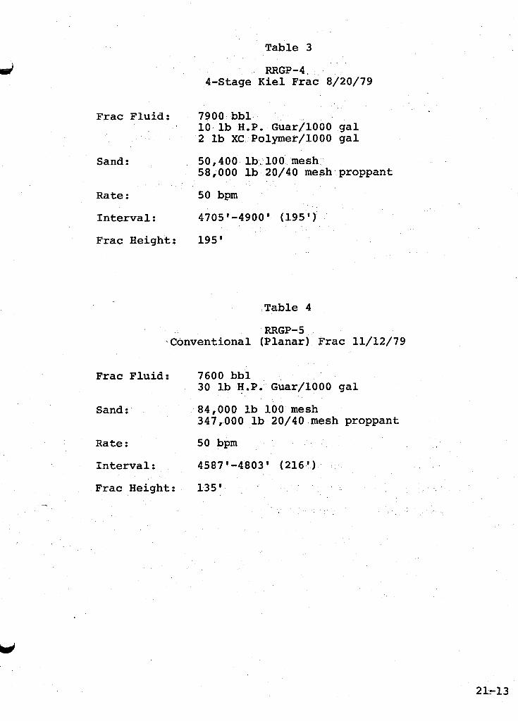
In summary, RRGP-4 and RRGP-5 were successfully recompleted and fracture treated, although the desired stimulation results were not achieved. Well RRGP-4 w a s stimulated from a productivity index of essentially 0 to 0.6 gpm per psi. Well RRGP-5 has a post-stimulation PI of 2.0 gpm per psi, only slightly higher than before the treat- ment, and no significant increase in temperature was achieved. Summaries of the stimulation treatments are presented in Tables 3 and 4.
STIMULATION TREATMENTS AT EAST MESA
The East Mesa field, in the Imperial Valley of California, is a moderate temperature reservoir producing from a sandstone and siltstone matrix. Several features of East Mesa made it an excellent choice for the second set of field experiments. The reservoir is known in more detail than most other geothermal reservoirs and this in-depth knowledge provides a sound basis for designing and evaluating stimulation treatments. The moderate temperature range (32O0-35O0F) was the next logical step from Raft River conditions in the evaluation of fracture fluids, proppants, and mechanical
U
21-9

I--
1
equipment. The selection of a matrix-type reservoir was also important at this stage of the program. successfully predicted in matrix-type reservoirs in the petroleum industry, and the existing interpretive techniques should transfer to geothermal reservoirs. Furthermore, the reservoir fluids, with a total dissolved solids content of about 2,000 mg/l, are not expected to chemically interfere with the stimulation fluids or tracers.
Fracture geometry has been
dps
Well 58-30, selected for these experiments, is ideally suited Unlike many other geothermal wells at East Mesa and mechanically.
elsewhere, it is completed with a cemented, jet perforated liner. This afforded an opportunity to easily and cheaply isolate zones o f a size that can be effectively treated and evaluated. The first treat- ment was a conventional planar type hydraulic fracture of a 250-foot low permeability sandstone interval near the bottom of the well. This zone has good sand development, but the permeability has been severely reduced because of authigenic cementation by carbonate minerals. Porosity is still high enough, however, to provide good storage capacity. A fracture treatment of this zone is intended to create a high conductivity linear flow channel in the low permeability area surrounding the well, in a manner similar to that desired in conventional oil and gas well stimulations, thereby enhancing the flow capacity. The treatment consisted of 2,800 barrels of a viscous crosslinked polymer frac fluid and 163,000 lbs of sand. the treatment.
The fluid was pumped at an average rate of 40 bpm during
The second treatment was a dendritic type fracture treatment in a shallower, cooler, higher permeability, 300-foot interval of the same well. This upper zone, drilled with a predominantly bentonitic mud system, has good sands (high porosity and permeability) which show permeability impairment near the wellbore. zones should break through the mud and cement damage near the wellbore such that fluid can more easily flow into the well from the formation. The treatment consisted of 10,300 barrels of low viscosity frac fluid (HI? Guar) and 44,000 lbs of 100-mesh sand pumped in five stages at an average rate of 48 bpm. The job was terminated before completing an originally planned eight stages and 15,600 barrels because the rate/pressure history of the job indicated there was little to be gained by pumping the last three stages. The 100-mesh sand was used as a fluid-loss control agent in the 50 md permeable sandstone interval that was fractured.
to evaluate the fracture experiment on the upper zone. section of the well, from 6,547 feet to TD, was sanded back to
A mini-frac of tkiese
From July 25 to August 2, 1980, the well was production tested The lower
21-10

prevent flow from the lower frac zone. The well flowed an average of 135,000 lbs per hour. Reservoir pressure buildup data show the total open interval permeability-thickness was 9,881 md-ft, or approxi- mately a 2.5-fold increase in productivity for the upper frac zone. This analysis indicates the shallow hydraulic stimulation treatment of the high permeability, upper interval was very successful. The upper zone treatment to correct near wellbore damage is of particular importance because such mud and cement damage is believed to be a common cause of impairment in Imperial Valley wells.
Well clean-out operations were initiated in August to remove the sand covering the lower frac zone. nitrogen) parted and left approximately 5,170 ft of tubing in the hole. Fishing and clean-out operations were in progress at the time of reporting. A production test of the entirqwellbore will be performed to evaluate the lower frac job. Summaries of the stimulation treatments are presented in Tables 5 and 6.
The coil tubing (used to inject
CONCLUSIONS
An effective stimulation treatment requires the interaction of four separate items:
0
0 Frac fluids Proppants
Planned and properly engineered procedures. 0 Equipment 0
While there are good fluid systems and proppants available, only judicious combinations and a well thought-out procedure which uses all of these materials and available equipment to best advantage will result in an optimum stimulation treatment. Generally, high flow rates and convective cooling can be used either with conventional (planar) fracturing or with a dendritic fracturing technique. Many of today's fluid systems have been tested to above 400°F. Some fluids have survived quite well. Current tests on proppants have shown temperature sensitivities in sand; however, there are resin- coated materials and sintered bauxite which are not very temperature sensitive. fluid systems and proppants to geothermal wells because temperature, water chemistry, and formation properties vary greatly from field to field.
Much more work is required in the specific application of
I
21-11

21-12
Table 1
Major Tasks Phase I
Technology Review
Technology Transfer Equipment Review - Surface Equipment Review - Downhole
Stimulation Materials Evaluation
Fracture Fluid Evaluation Fracture Proppant Evaluation Recent Stimulation Technology Development
Chemical Stimulation Analysis Analysis
Numerical Simulation
Numerical Model Development Numerical Analysis
Table 2
Major Tasks - Phase I1
Planning Field'Experiments
Reservoir Identification, Evaluation and Qualification
Well Identification, Evaluation and Qualification Prepare Specific Well Experiment Environmental and Permitting Field Experiment Administration Planning Specifications and Subcontracting
Field Experiment and Analysis
Design and Provide Surface Production Facilities Field Experiment and Production Testing Monitoring and Data Collection Data Analysis and Interpretation Radioactive Tracers
Project Reporting and Management
Geothermal Well Stimulation Symposium
,
Table 3
RRGP-4, 4-Stage K i e l F r a c 8/20/79
F r a c F l u i d : 7900 bbl 1 0 l b HOP. Guar/1000 ga l 2 I b XC Polymer/1000 ga l
58,000 l b 20/40 mesh proppant Sand : 50,400 lb..100 mesh
R a t e : 50 bpm
I n t e r v a l : 4705'-4900' (195 ' )
F r a c Height : 195 '
7
Table 4
RRGP-5 \Conventional (P lanar ) F r a c 11/12/79
F r a c F l u i d : 7600 bbl 30 l b H.P. G u a r f l O O O gal
347,000 lb 20/40 mesh proppant Sand : 84,000 l b 100 mesh
R a t e : 50 bpm
I n t e r v a l : 4587'04803' (216 ' )
F r a c Height : 135 '
21-13

1 I
I 21-14
Table 5
East Mesa 58-30 (Deep Zone) Conventional (Planar) Frac 7/3/79 ii
Frac Fluid: 2800 bbl Crosslinked polymer gel 20 lb calcium carbonate/1000 gal
(fluid loss additive in prepad and pad)
Sand : 44,500 lb 100 mesh 59,200 lb 20/QO mesh 60,000 lb 20/40 mesh "Supersand"
Rate : 40 bpm
Interval : 6587'-6834' (247'
Formation: 350OF-15 md
Table 6
East Mesa 58-30 (Shallow Zone) 5-Stage Kiel Frac 7/6/80
Frac Fluid: 10,300 bbl 10 lb H.P. Guar/1000 gal 2 lb XC Polymer/1000 gal 20 lb calcium carbonate/1000 gal
(fluid loss additive)
Sand : 44,000 lb 100 mesh
Rate : 48 bpm
Interval : 4952'-5256' (304')
Formation: 325OF-50 md

I I : ’ I
i
FIGURE 1. PROJECT ORGANIZATION, GEOTHERMAL RESERVOIR WELL STIMULATION PROGRAM
5000 . 10000 0
CLOSURE STRESS (oil) ’ CLOSURE STRESS (psi)
FIGURE 2. TEMPERATURE EFFECTS ON FIGURE 3. PERMEABILITY VS. CLOSURE 2WO BRADY TEXAS GAND 8 STRESS FOR TEMPERATURE
INSENSITIVE PROPPANTS
21-15
W
! E E L x 5
W 0
- B W
8 s a 5
1 - W c
0 a a
i a a 0
'OW I loo
40
10
4
.. POLYMER %'
WITH METHANOL WITHOUT METHANOL
TEWERATURE (OF)
FIGURE 4. POLYMER-WATER FRAC FLUID . VISCOSITY VS. TEMPERATURE
TIME (hrs.)
FIGURE 5. DIORADATION OF HP-GUAR IN DEIONIZED WATER
\ 25ooc .~--.-..-.-...............- * * I I * * ' I I I I ' '
0 4 E 16 20 24
FIGURE 6. DEGRADATION OF HEC IN DEIONIZED WATER
21-16
I I
. 26 i MW-6 0 I1 100')
I ! i a I
I RRGl - 7
FIGURE 7. RAFT RIVER FACILITY WITH GEOLOGIC STRUCTURE AND WELL LOCATIONS
21-17
B TOP VIEW !
13 3 W C I S l N G
- 1887’
KICK-OFF 3555 UICK-OFF 3526
~ T D S 1 1 0
N 1 0 0 W
FIGURE 8. SCHEMATIC OF WITH 7” LINER
RAFT RIVER IN PLACE
FIGURE 9. IDEALIZED SCHEMATIC OF A DENDRITIC FRACTURE (AFTER KIEL)
- - 24,- W LINED PI1
WATER SU?PLV
--+ CRAC TANKS
RRGP-4
FIGURE 10.EQUIPMENT LAYOUT FOR RRGP-4 FRAC TREATMENT
8 .
21-18