a review of the proposed kisi offset-secant method for ... · size-independent linear-elastic...
TRANSCRIPT
A Review of the Proposed KIsi Offset-Secant Method for
Size-Independent Linear-Elastic Toughness Evaluation
Mark James1
Doug Wells2
Phillip Allen2
Kim Wallin3
1 Arconic Technology Center
2 NASA MSFC/Damage Tolerance Assessment Branch
3VTT Nuclear Safety, VTT, Finland
1
https://ntrs.nasa.gov/search.jsp?R=20170005327 2019-03-25T13:04:08+00:00Z

2
Contents
• Size Dependence in KIc per E399
• The KIsi Proposal
• Questions of Linear Elasticity and Plasticity
• An Evaluation of KIsi for Plasticity
• Analytical Assessments
• Model Scaling •Size independent parameters
• Material Space
• Results
• Conclusions

• Toughness test results for KIc from ASTM E399 are dependent upon specimen
size for Type I force-displacement curves due to R-curve effects.• Wallin, K. R. W., “Critical Assessment of ASTM E399.” Fatigue and Fracture Mechanics:
34th Volume, ASTM STP 1461, S.R. Daniewciz, J.C. Newman, and K.H. Schwalbe, Eds,
ASTM International, 2004.
3
Size Dependence in KIc per E399:
E399, Type I Assessment:
• 5% offset secant
• Assumes all compliance change is
due to crack extension
• Corresponds to crack extension
equal to approximately 2% of the
specimen’s original ligament, bo.
CMOD, v
Fo
rce,
P
5% Offset Secant
PQ
Pmax
Measured KIc is a function of
specimen size based on bo
Type I, Rising R-Curve Behavior
Pmax/PQ ≤ 1.1

4
A proposed toughness measure without size dependence: KIsi (Wallin, 2004)
• A new optional toughness parameter, KIsi , does not replace KIc in E399
• Utilizes an offset secant that is a function of the specimen size (bo)
• Targets a consistent 0.5mm of predicted crack extension.
• Reduces the specimen size dependence in the toughness result
The KIsi Proposal
Two Proposed validity changes:
1. Ligament requirement
From: bo ≥ 2.5(K/sys)2
To: bo ≥ 1.1(K/sys)2.
2. Remove requirement that Pmax/PQ ≤ 1.1
CMOD, v
Fo
rce,
P
Variable Offset Secant
PQ
This methodology also assumes
that all compliance change is due
to crack extension.

5
The KIsi Proposal, Continued
• For E399 KIc assessment, the offset secant
DC = 5% for all specimens.
• For KIsi, DCsi is proposed to follow this
convention for the C(T) specimen:
DCsi = 135/(W-a) (for mm dimensions)
• For common E399 inch-sized specimens
with a/W = 0.5:
W = 25.4 mm (1 inch), DCsi = 10.6%
W = 50.8 mm (2 inch), DCsi = 5.3%
W = 101.6 mm (4 inch), DCsi = 2.7%
Dv
CMOD, v
Fo
rce
oo
o
vC
P
100i oi
o
C CC
C
D
The KIsi Variable Secant
Change in compliance (DC):
• Percent increase in compliance (or percent decrease in slope) of the force vs.
displacement trace with respect to the initial linear portion of test record
DC = DCcrack ext + DCplasticity + DCexperimental error
6
Questions of Linear-Elasticity and Plasticity
*Wang, Yangyi, “A Two Parameter Characterization of Crack Tip Fields and Applications to Cleavage Fracture,” PhD Diss, MIT, 1991
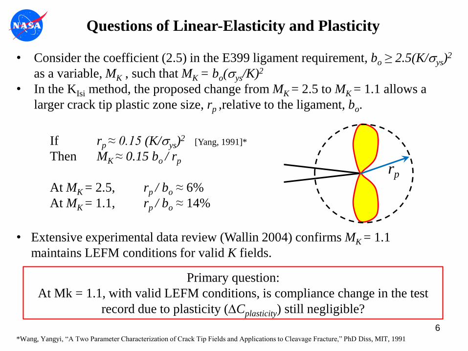
• Consider the coefficient (2.5) in the E399 ligament requirement, bo ≥ 2.5(K/sys)2
as a variable, MK , such that MK = bo(sys/K)2
• In the KIsi method, the proposed change from MK = 2.5 to MK = 1.1 allows a
larger crack tip plastic zone size, rp ,relative to the ligament, bo.
If rp ≈ 0.15 (K/sys)2 [Yang, 1991]*
Then MK ≈ 0.15 bo / rp
At MK = 2.5, rp / bo ≈ 6%
At MK = 1.1, rp / bo ≈ 14%
rp
• Extensive experimental data review (Wallin 2004) confirms MK = 1.1
maintains LEFM conditions for valid K fields.
Primary question:
At Mk = 1.1, with valid LEFM conditions, is compliance change in the test
record due to plasticity (DCplasticity) still negligible?

Objectives of current study:
1. Determine if compliance change in the force (P) versus CMOD (v) record
due to plasticity (DCplasticity) makes the KIsi variable offset secant method
incompatible with MK = 1.1.
The method is incompatible if DCplasticity ≥ DCsi with MK ≥ 1.1
2. Confirm assumptions that linear elastic-conditions prevail at MK = 1.1
such that the crack tip fields remain K-dominant.
Approach:
1. Evaluate DC in P-v record with finite element models over a substantial
material property space as deformation increases to MK = 1.1
There is no DCcrack_extension contribution in the finite element model
2. Evaluate the contribution of plasticity to crack driving force (through
KJplastic) as deformation increases to MK = 1.1.
7
An Evaluation of KIsi for Plasticity
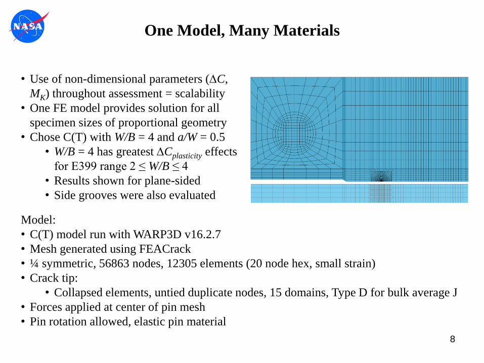
• Use of non-dimensional parameters (DC,
MK) throughout assessment = scalability
• One FE model provides solution for all
specimen sizes of proportional geometry
• Chose C(T) with W/B = 4 and a/W = 0.5
• W/B = 4 has greatest DCplasticity effects
for E399 range 2 ≤ W/B ≤ 4
• Results shown for plane-sided
• Side grooves were also evaluated
8
One Model, Many Materials
Model:
• C(T) model run with WARP3D v16.2.7
• Mesh generated using FEACrack
• ¼ symmetric, 56863 nodes, 12305 elements (20 node hex, small strain)
• Crack tip:
• Collapsed elements, untied duplicate nodes, 15 domains, Type D for bulk average J
• Forces applied at center of pin mesh
• Pin rotation allowed, elastic pin material
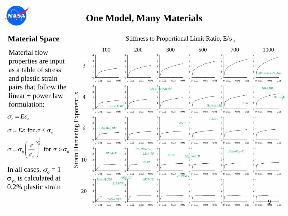
Material Space
o oEs
1
for
for
o
n
o o
o
Es s s
s s s s
Material flow
properties are input
as a table of stress
and plastic strain
pairs that follow the
linear + power law
formulation:
In all cases, so = 1
sys is calculated at
0.2% plastic strain
0 0.01 0.03 0.05
0
1
2
3
4
0 0.01 0.03 0.05
0
1
2
3
4
0 0.01 0.03 0.050
1
2
3
4
0 0.01 0.03 0.050
1
2
3
4
0 0.01 0.03 0.05
0
1
2
3
4
0 0.01 0.03 0.05
0
1
2
3
4
0 0.01 0.03 0.05
0
1
2
3
4
0 0.01 0.03 0.05
0
1
2
3
4
0 0.01 0.03 0.050
1
2
3
4
0 0.01 0.03 0.050
1
2
3
4
0 0.01 0.03 0.05
0
1
2
3
4
0 0.01 0.03 0.05
0
1
2
3
4
0 0.01 0.03 0.05
0
1
2
3
4
0 0.01 0.03 0.05
0
1
2
3
4
0 0.01 0.03 0.050
1
2
3
4
0 0.01 0.03 0.050
1
2
3
4
0 0.01 0.03 0.05
0
1
2
3
4
0 0.01 0.03 0.05
0
1
2
3
4
0 0.01 0.03 0.05
0
1
2
3
4
0 0.01 0.03 0.05
0
1
2
3
4
0 0.01 0.03 0.050
1
2
3
4
0 0.01 0.03 0.050
1
2
3
4
0 0.01 0.03 0.05
0
1
2
3
4
0 0.01 0.03 0.05
0
1
2
3
4
0 0.01 0.03 0.05
0
1
2
3
4
0 0.01 0.03 0.05
0
1
2
3
4
0 0.01 0.03 0.050
1
2
3
4
0 0.01 0.03 0.050
1
2
3
4
0 0.01 0.03 0.05
0
1
2
3
4
0 0.01 0.03 0.05
0
1
2
3
4
20
10
6
4
3
100 200 300 500 700 1000
Str
ain
Har
den
ing
Ex
po
nen
t, n
Stiffness to Proportional Limit Ratio, E/so
2219-T8
2195-T8
300 series SS. Ann
2219-T8 FSWeld
Ti-6-4 STA
7050-T7Mar-M-250
AirMet-100
A514
A537
A572
A36
1010 HR
6061-T6Al 5000’s
Hastelloy-XIN718 STA
Haynes 188
Be
Cu-Be TF00
4340
Mg, AZ31BHP9-4-30
9
One Model, Many Materials
10
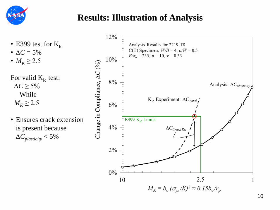
Results: Illustration of Analysis
• E399 test for KIc
• DC = 5%
• MK ≥ 2.5
For valid KIc test:
DC ≥ 5%
While
MK ≥ 2.5
• Ensures crack extension
is present because
DCplasticity < 5%

11
Results: KIsi Trouble at MK = 1.1
• DCsi shown for W = 25,
50, 75, 100, and 125mm
• MK = 1.1 limit shown
Proposed KIsi method:
DC ≥ DCsi
While
MK ≥ 1.1
Issue:
• DCplasticity > DCsi
With MK ≥ 1.1
• Does not ensure crack
extension!
• Confirmation:
• Plastic contribution to KJ
is small, LEFM is good
to MK = 1.1!

100 200 300 500 700 10000
1
2
3
4
5
6
7
E / sprop lim
%K
J p
last
ic a
t Mk
= 1.
1
n=3
n=4
n=6
n=10
n=20
12
Results: Material Influence
100 200 300 500 700 10000
2
4
6
8
10
12
E / sprop lim
% C
ompl
ianc
e C
hang
e at
Mk
= 1.
1
n=3
n=4
n=6
n=10
n=20
KIsi
W = 1
KIsi
W = 2
KIsi
W = 4
%DC at MK = 1.1All Materials
Plastic Contribution to KJ at MK = 1.1All Materials
• Plasticity effects on compliance reflect plastic contribution to KJ
• Influence of strain hardening depends upon E/so ratio
• Low hardening (n = 20) eliminates effects of E/so ratio
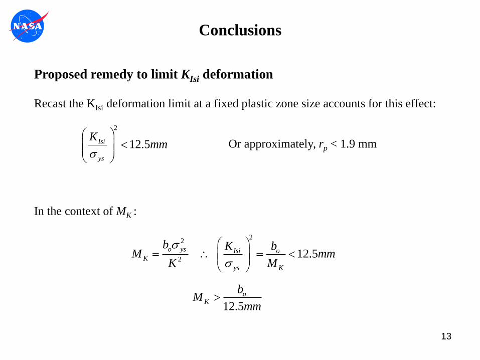
Proposed remedy to limit KIsi deformation
Recast the KIsi deformation limit at a fixed plastic zone size accounts for this effect:
13
2
12.5Isi
ys
Kmm
s
In the context of MK :
22
2 12.5
o ys Isi oK
ys K
b K bM mm
K M
s
s
12.5
oK
bM
mm
Conclusions
Or approximately, rp < 1.9 mm

0.811.11.522.5468100
2
4
6
8
10
12
MK = b
o s
ys
2 / K2
%D
in C
ompl
ianc
e,
%K
J p
last
ic,
%A
ppar
ent C
rack
Ext
.
%D in Compliance
%Plastic in KJ
% Apparent Crack Ext.
KIsi
W = 1 (25mm)
KIsi
W = 2 (51mm)
KIsi
W = 4 (102mm)
KIc
Bounds
14
2
12.5Isi
ys
Kmm
s
Conclusions
15
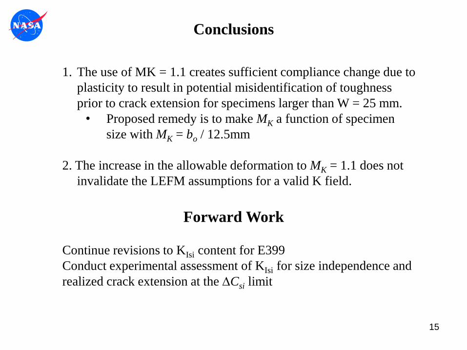
Conclusions
1. The use of MK = 1.1 creates sufficient compliance change due to
plasticity to result in potential misidentification of toughness
prior to crack extension for specimens larger than W = 25 mm.
• Proposed remedy is to make MK a function of specimen
size with MK = bo / 12.5mm
2. The increase in the allowable deformation to MK = 1.1 does not
invalidate the LEFM assumptions for a valid K field.
Forward Work
Continue revisions to KIsi content for E399
Conduct experimental assessment of KIsi for size independence and
realized crack extension at the DCsi limit

Back-up
• Model compliance confirmation
• W/B = 4 versus W/B = 2
• 3D versus Plane Strain Effects
• Side Groove Effect for W/B = 4
16
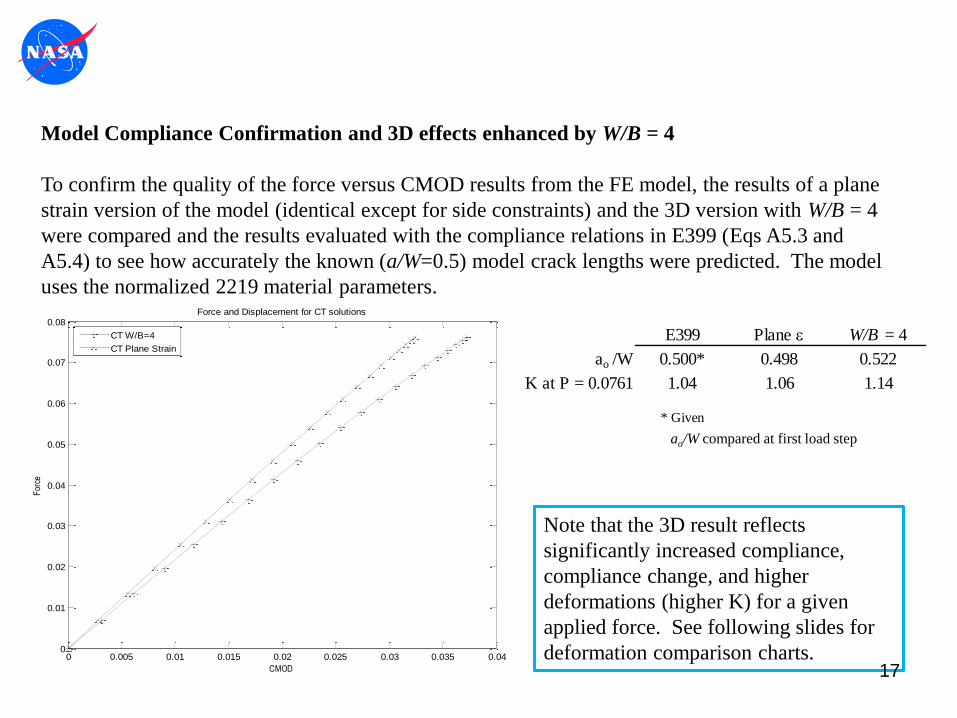
Model Compliance Confirmation and 3D effects enhanced by W/B = 4
To confirm the quality of the force versus CMOD results from the FE model, the results of a plane
strain version of the model (identical except for side constraints) and the 3D version with W/B = 4
were compared and the results evaluated with the compliance relations in E399 (Eqs A5.3 and
A5.4) to see how accurately the known (a/W=0.5) model crack lengths were predicted. The model
uses the normalized 2219 material parameters.
0 0.005 0.01 0.015 0.02 0.025 0.03 0.035 0.040
0.01
0.02
0.03
0.04
0.05
0.06
0.07
0.08
CMOD
For
ce
Force and Displacement for CT solutions
CT W/B=4
CT Plane Strain
E399 Plane W/B = 4
ao /W 0.500* 0.498 0.522
K at P = 0.0761 1.04 1.06 1.14
* Given
Note that the 3D result reflects
significantly increased compliance,
compliance change, and higher
deformations (higher K) for a given
applied force. See following slides for
deformation comparison charts.
ao/W compared at first load step
17
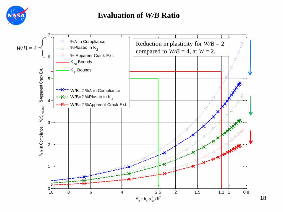
180.811.11.522.546810
0
1
2
3
4
5
6
7
MK = b
o s
ys
2 / K2
%D
in C
ompl
ianc
e,
%K
J p
last
ic,
%A
ppar
ent C
rack
Ext
.
%D in Compliance
%Plastic in KJ
% Apparent Crack Ext.
KIsi
Bounds
KIc
Bounds
W/B=2 %D in Compliance
W/B=2 %Plastic in KJ
W/B=2 %Apparent Crack Ext.
Reduction in plasticity for W/B = 2
compared to W/B = 4, at W = 2.W/B = 4
Evaluation of W/B Ratio

190.811.11.522.546810
0
1
2
3
4
5
6
7
MK = b
o s
ys
2 / K2
%D
in C
ompl
ianc
e,
%K
J p
last
ic,
%A
ppar
ent C
rack
Ext
.
%D in Compliance
%Plastic in KJ
% Apparent Crack Ext.
KIsi
Bounds
KIc
Bounds
Plane Str, %D in Compliance
Plane Str. %Plastic in KJ
Plane Str. %Apparent Crack Ext
W/B = 4Reduction in plasticity for plane strain
compared to W/B = 4, at W = 2.
3D effects are significant at
deformations higher than MK = 2.5
Evaluation of W/B = 4 versus Plane Strain

20
Side Grooved Specimen:
To evaluate the effects of the side-
grooved geometry on the force-
CMOD non-linearity due to
plasticity, a model with side-
grooves was run using the
normalized 2219-T8 material
model.
Dimensions:
W = 2
a/W = 0.5
B = 0.5
BN = 0.4
Be = 0.48
SG angle = 90°
Modeled with quarter
symmetry
Evaluation of Side Groove Effects
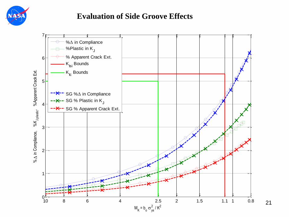
21
Reduction in plasticity is not
significant for side grooves on
W/B = 4, at W = 2.
0.811.11.522.5468100
1
2
3
4
5
6
7
MK = b
o s
ys
2 / K2
%D
in C
ompl
ianc
e,
%K
J p
last
ic,
%A
ppar
ent C
rack
Ext
.
%D in Compliance
%Plastic in KJ
% Apparent Crack Ext.
KIsi
Bounds
KIc
Bounds
SG %D in Compliance
SG % Plastic in KJ
SG % Apparent Crack Ext.
Evaluation of Side Groove Effects

Model Scaling:Given the objective of KIsi is to reduce specimen size dependence, to
evaluate the method, either models need to be run at different sizes,
shown to be scalable, or evaluated by parameters that are size
independent.
22
22
2 2 2
oo o
o oCT o o
o o o
bb
BbP b
W a b b
ss
s
To evaluate scaling, consider the characteristic load expression for the
C(T) specimen, reduced for a/W=0.5, W/B=4, and choosing ligament bo
as a characteristic length:
For two different size C(T) specimens (subscripts 1 and 2) with the same
proportional geometry and material, forces may be scaled relative to their
respective characteristic loads:
222 2 21 2 2
2
1 2 1 1 1 1
and for =CT o o
CT CT CT o o
P b bP P P
P P P P b b 2
2 1P P
Following similar logic, 1
2 1 2 1 2 and and C
v v K K C
2 2 2
1 1
2 122 2
11
so o ys o ys o ys
K K K
b b bM M M
K KK
s s s
1 1
2 11
100
i o
i io
C C
C CC
D D
Given this, we confirm the deformation parameter MK is size independent: …and the % change in compliance is size independent:
Only one model for the C(T) geometry W/B=4 with a/W=0.5 is required to study size effects.
0 0.01 0.02 0.03 0.04 0.05 0.06 0.07 0.080
0.05
0.1
0.15
0.2
0.25
0.3
0.35
CMOD
For
ce
Scaling of Force and Displacement for CT solutions
CT W = 2
CT W = 4
W = 2 result sclaed to W = 4
Two separate models, W=2 and W=4.
Force versus CMOD results are plotted.
W=2 results are scaled by = 2
and plotted as open circles.
See discussion on
following chart.
22

Executive Summary:The proposed size-independent linear-elastic fracture toughness, KIsi, for potential inclusion in ASTM
E399 targets a consistent 0.5mm crack extension for all specimen sizes through an offset secant that is
a function of the specimen ligament length. The KIsi method also includes an increase in allowable
deformation, and the removal of the Pmax/PQ criterion. A finite element study of the KIsi test method
confirms the viability of the increased deformation limit, but has also revealed a few areas of concern.
Findings:
1. The deformation limit, bo ≥ 1.1(KI /sys)2 maintains a K-dominant crack tip field with limited
plastic contribution to the fracture energy.
2. The three dimensional effects on compliance and the shape of the force versus CMOD trace are
significant compared to a plane strain assumption
3. The non-linearity in the force versus CMOD trace at deformations higher than the current limit
of 2.5(KI /sys)2 is sufficient to introduce error or even “false calls” regarding crack extension
when using a constant offset secant line. This issue is more significant for specimens with W ≥ 2
inches.
4. A non-linear plasticity correction factor in the offset secant may improve the viability of the
method at deformations between 2.5(KI /sys)2 and 1.1(KI /sys)
2 .
23

24
Conclusions:
1. The deformation limit, bo ≥ 1.1(KI /sys)2 maintains a K-dominant crack tip field with limited
plastic contribution to the fracture energy, i.e. the plastic portion of KJ ≈ 5%
2. The three dimensional effects on compliance and the shape of the force versus CMOD trace
are significant compared to a plane strain assumption (see back-up charts). Plane strain is
assumed in the compliance relations and offset slope percentage in E399
3. The non-linearity in the force versus CMOD trace at deformations higher than the current
limit of 2.5(KI /sys)2 is sufficient to introduce error or even “false calls” regarding crack
extension when using a constant offset secant line. This issue is more significant for
specimens with W ≥ 2 inches. Side grooving the specimen does not significantly effect the
non-linearity in the trace (see back-up charts).
4. The ability for the proposed KIsi method to collapse size-dependence in historical data may be
related to specimens having been sized close to the 2.5(KI /sys)2 limit. The success of the
method for specimens with deformations closer to 1.1(KI /sys)2 at toughness may not be
robust.
5. A non-linear plasticity correction factor in the offset secant may improve the viability of the
method at deformations between 2.5(KI /sys)2 and 1.1(KI /sys)
2 .