a review on evaluation of pv models based … 2 issue 12.pdfthe three level space vector modulation...
TRANSCRIPT

NOVATEUR PUBLICATIONS INTERNATIONAL JOURNAL OF INNOVATIONS IN ENGINEERING RESEARCH AND TECHNOLOGY [IJIERT]
ISSN: 2394-3696 VOLUME 2, ISSUE 12, DEC.-2015
1 | P a g e
A REVIEW ON EVALUATION OF PV MODELS BASED ON AN
INTEGRATION USING A NEW CONFIGURATION OF A
THREE-LEVEL INVERTER
Rashmi B. Chaudhari
PG Student,
Department of Electrical Engineering,
NMU University, Bhusawal, India,
Prof.G.K.Mahajan
Guide,
Department of Electrical Engineering,
NMU University, Bhusawal, India,
Prof.A.P.Chaudhari
HOD,
Department of Electrical Engineering,
NMU University, Bhusawal, India,
ABSTRACT
The effect of linear imbalances and nonlinear loads on the voltage balance of the neutral-point-
clamped converters is described in this paper. The Neutral-Point-Clamped inverters are used in
the multilevel inverters for high power applications. In this paper a three level NPC inverter that
couple accommodate with solar photovoltaic (PV) and battery storage in grid connected system.
The three level space vector modulation technique (SVPWM) is proposed. The SVPWM correct
the ac voltage under unbalance dc voltage condition.SV-PWM strategy makes it possible to
control the neutral point voltage by optimum choice of switch sequence for any position and
length of output voltage vector. The control scheme has capability to control the power delivery
between the solar PV, battery, and grid, it simultaneously provides maximum power point
tracking (MPPT) operation for the solar PV. The results of matlab modeling of the system detail
the comparative operation of inverter topologies which are the conventional two level inverters
and multilevel inverter topology to reduce total harmonic distortions in grid voltage and
electromagnetic interference. Three-level NPC voltage source inverter that can integrate both
renewable energy and battery storage on the dc side of the inverter has been presented. The
effectiveness of the proposed methodology is investigated by the simulation of several scenarios,
including battery charging and discharging with different levels of solar irradiation.
KEYWORDS - Solar photovoltaic (PV), Battery storage, Space vector modulation (SVM),
three level NPC inverter.

NOVATEUR PUBLICATIONS INTERNATIONAL JOURNAL OF INNOVATIONS IN ENGINEERING RESEARCH AND TECHNOLOGY [IJIERT]
ISSN: 2394-3696 VOLUME 2, ISSUE 12, DEC.-2015
2 | P a g e
INTRODUCTION
Nowadays the demand for power is increases all over the world and this cannot be met by the
conventional sources because it going to be vanishes. And also there are so many environmental
problems, energy crises due to the conventional power generation [1]. This can be replace by
using the renewable energy sources like solar photovoltaic (PV) wind sources etc. for generation
of electricity.
Advance power electronic configuration are to be used for developing energy from the
renewable energy sources. The maximum energy from solar PV are utilize by using the power
electronic systems [2]-[3]. For three phase application, two types of power electronic
configuration are required to transfer the power to the grid: 1) single stage conversion 2) double
stage conversion.
In single stage conversion, only one converter is sufficient to fulfil the requirement of double
stage converter. Hence this system will have lower cost and higher efficiency but the complex
method is required. For three phase high power applications in industry, single stage conversion
of solar PV is achieved by using the voltage source converter (VSC)[4].
In double stage conversion for solar PV two steps are applied i.e. firstly dc/dc converter is used
and second stage is dc/ac inverter. In first stage the function of dc/dc converter is to facilitate the
maximum power point tracking (MPPT) of the PV array to produce the appropriate dc voltage
for dc/ac inverter. In second stage i.e. inversion stage, the inverter produce the three phase
sinusoidal voltage and current and also reduces the harmonic content in the grid injected voltage
and current afterwards it transfer power to load connected grid.
Due to the unpredictable and fluctuating nature of solar PV the output of this system is never be
constant. To overcome this difficulty a battery storage system is employed. It can boost the
system flexibility and also increase the availability of the system [2]. Generally the grid
connected solar PV system require a two converters first which control the charging and
discharging of the battery storage system and another converter is required to convert dc/ac
power conversion for grid.This paper is concern with the design and study of a grid connected
three phase solar PV system integrated with battery storage by using single three level NPC
inverter having the capability of MPPT and ac side current control and also having the ability of
controlling the charging and discharging of battery storage.
Since the introduction in 1981 [5] three level neutral point clamped (NPC) voltage source
inverter are widely used in high power applications, it having the advantages over the
conventional two level inverter for high power applications. To increase the performance of this
converter, the voltages of two series connected dc link capacitors must be cramped to one half
the level of dc link voltage. Most of the industry need to increase the efficiency and ants to
reduce the production costs and this can be achieve by increasing the installation of high power
electrical equipment and another way is to develop the multilevel inverter in the system.

NOVATEUR PUBLICATIONS INTERNATIONAL JOURNAL OF INNOVATIONS IN ENGINEERING RESEARCH AND TECHNOLOGY [IJIERT]
ISSN: 2394-3696 VOLUME 2, ISSUE 12, DEC.-2015
3 | P a g e
STRUCTURE OF NEW CONTROL STRATEGY
A. Three Level Inverter
Fig. 1 shows the typical three level neutral point clamped NPC inverter, they have been widely
used in several application such as motor drives, STATCOM, HVDC, Pulsewidth modulation
(PWM), active power filters (APF), renewable energy applications, etc.The main advantages of
these inverters are improving quality of voltage waveforms and an increase in the dc-link voltage
for a given blocking voltage capacity of the semiconductors. The converter has two capacitors in
the DC side to produce the three-level AC side phase voltages. Normally, the capacitor voltages
are assumed to be balanced, since it has been reported that unbalance capacitor voltages can
affect the AC side voltages and can produce unexpected behavior on system parameters such as
even-harmonic injection and power ripple [6].
Several methods have been introduced to balance the capacitor voltage [5], [6], [7]. They are as
follows:
Various strategies have been proposed to balance the capacitor voltages using modulation
algorithms; one among them is sinusoidal carrier-based PWM (SPWM) or Space Vector Pulse-
Width Modulation (SVPWM) [8], it is explain in next section.
(a) (b)
Fig.1 (a) ATypical three level NPC inverter, (b) Space vector diagram of the NPC inverter
B. Different Capacitors Voltages
In SVPWM, most of the strategies are based on injecting the appropriate zero-sequence signal in
to the modulation signals to balance the DC-link capacitors [9].
In vector control theory, ideally, the inverter must be able to generate the voltage output
instantaneously, following the reference vector (��������������� ), generated by the control system.
However, because of the limitation of the switches in the inverter, it is not possible to guarantee
that any requested vector can be generated; as a matter of fact, only a limited number of vectors
(27 vectors for three-level inverter) can be generated.
To overcome such difficulties, in any space vector modulation scheme such as SVPWM and
SVPWM, the reference vector, is generated by selecting the appropriate available vectors in each

NOVATEUR PUBLICATIONS INTERNATIONAL JOURNAL OF INNOVATIONS IN ENGINEERING RESEARCH AND TECHNOLOGY [IJIERT]
ISSN: 2394-3696 VOLUME 2, ISSUE 12, DEC.-2015
4 | P a g e
time frame in such a way that the average of the applied vectors must be equal to the reference
vector.
Equation (1) shows the mathematical relation between the timing of the applied vectors and the
reference vector:
(1)
Where Tsis the time frame and preferred to be as short as possible. Tiis the corresponding time
segment for selected inverter vector Viand n is the number of applied vectors.
Generally, the reference vector is generated by the three nearest different vector (n = 3), and (1)
can be converted to three different equation with three variables T1, T2, and T3to be calculated.
Fig. 1(b) shows the space vector diagram of a three-level inverter for balanced dc-link capacitors
[5] this diagram shows, the numbers associated with each vectors represent the commutation
state of the inverter for phase a, b and c respectively; 0 indicates that the corresponding phase is
connected to the bottom of the DC-link, 1 to the NP and a 2 to the top.
It consist of four sets of vectors having their effect on different capacitor voltages. There are six
large vectors (200, 220, 020, 022, 002, and 202), six medium vectors (210, 120, 021, 012, 102,
and 201), the short or redundant vectors (100-211, 110- 221, 010-121, 011-122, 001-112, and
101-212), and three zero vectors (000, 111, and 222). Unlike the zero and large vectors, the
medium vectors produce voltage imbalances on the capacitors caused by the connection of one
phase to the NP. Proper selection of the short vectors can contribute to compensate for such
imbalances.
For generating���������������, when one of the selections (������), is a short vector, then there are two choices
that can be made which can produce exactly the same effect on the ac side of the inverterin the
three wire connection (if voltages are balanced).Capacitor balancing in most reported three-level
NPC inverter applications is achieved by the proper selection of the short vectors.
Fig.2 A grid connected three-wire three-level inverter.

NOVATEUR PUBLICATIONS INTERNATIONAL JOURNAL OF INNOVATIONS IN ENGINEERING RESEARCH AND TECHNOLOGY [IJIERT]
ISSN: 2394-3696 VOLUME 2, ISSUE 12, DEC.-2015
5 | P a g e
Fig. 3. Vector diagram in the first sector of Fig. 1 (b) showing the change of the vectors
using balanced dc and unbalanced dc assuming Vc1 <Vc2.
Fig.2 shows dc and ac side of inverter which is connected to the grid through three level NPC
inverter. The dc side system shown by N consists of solar PV, a rectifying circuit, a battery
storage. The unbalancing of capacitor voltages causes the short and medium vector is of different
magnitude and angles as shown in fig. 1(b). Fig.3 shows the case where Vc1< Vc2. The
vector���Iis related to the switching stage, it can be calculated as:
���I= �
( VaN + � VbN + ��VcN) (2)
Where � = ��� � and VaN, VbN and VcNare the voltages of each phase with respect to N. The
vectors in the first sector is calculated by using equation (2) and the result are given from in (3) –
(9) these equation shows that the magnitude and angles of the vector is depending on the value of
capacitor voltages, similarly the vectors in the other sector is also calculated.
���sd1 = h (3)
���su1 = 1 - h (4)
����1 = 1 (5)
���l2 = �
� +
√
� j (6)
��� sd2 = h( �
� + √
� j ) (7)
��� su2 = ( 1 – h ) ( �
� + √
� j ) (8)
��� m1 = ( 1 - �
� ) + ℎ √
� � (9)
PROPOSED TOPOLOGY TO INTEGRATE SOLAR PV AND BATTERY
STORAGE
The two new configuration of a three level NPC inverter is integrated with battery storage and
solar PV as shown in fig. (4). Fig shows that there is no extra converter is required and this can
increase the overall efficiency of the system for both high and low power applications. Fig 4(a)
shows the basic configuration of the grid connected three level NPC inverter with battery storage
and solar PV. The power is transfer from system to the grid allowing the charging and
discharging of the battery by the control system.
NOVATEUR PUBLICATIONS INTERNATIONAL JOURNAL OF INNOVATIONS IN ENGINEERING RESEARCH AND TECHNOLOGY [IJIERT]
ISSN: 2394-3696 VOLUME 2, ISSUE 12, DEC.-2015
6 | P a g e
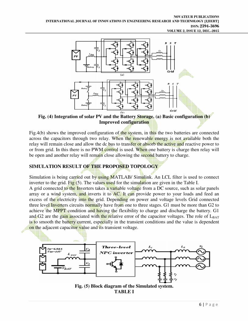
Fig. (4) Integration of solar PV and the Battery Storage. (a) Basic configuration (b)
Improved configuration
Fig.4(b) shows the improved configuration of the system, in this the two batteries are connected
across the capacitors through two relay. When the renewable energy is not available both the
relay will remain close and allow the dc bus to transfer or absorb the active and reactive power to
or from grid. In this there is no PWM control is used. When one battery is charge then relay will
be open and another relay will remain close allowing the second battery to charge.
SIMULATION RESULT OF THE PROPOSED TOPOLOGY
Simulation is being carried out by using MATLAB/ Simulink. An LCL filter is used to connect
inverter to the grid. Fig (5). The values used for the simulation are given in the Table I.
A grid connected to the Inverters takes a variable voltage from a DC source, such as solar panels
array or a wind system, and inverts it to AC. It can provide power to your loads and feed an
excess of the electricity into the grid. Depending on power and voltage levels Grid connected
three level Inverters circuits normally have from one to three stages. G1 must be more than G2 to
achieve the MPPT condition and having the flexibility to charge and discharge the battery. G1
and G2 are the gain associated with the relative error of the capacitor voltages. The role of LBAT
is to smooth the battery current, especially in the transient conditions and the value is dependent
on the adjacent capacitor value and its transient voltage.
Fig. (5) Block diagram of the Simulated system.
TABLE I

NOVATEUR PUBLICATIONS INTERNATIONAL JOURNAL OF INNOVATIONS IN ENGINEERING RESEARCH AND TECHNOLOGY [IJIERT]
ISSN: 2394-3696 VOLUME 2, ISSUE 12, DEC.-2015
7 | P a g e
PARAMETERS OF THE SIMULATED SYSTEM
Fig. (6) shows the inverter waveforms with respect to phase and reference.Fig.6(a) shows the
line to line voltage Vab, fig.6(b) shows the phase to midpoint voltage Vao, fig. 6(c), (d) and (e)
shows the reference voltage to neutral.
Fig. (6) Simulated inverter waveforms. (a) Vab-Phase to phase inverter voltage. (b) Vao-Inverter
phase voltage reference to midpoint. (c) Filtered VoN- Filtered inverter phase voltage reference to
midpoint. (d) Filtered VoN-Filtered midpoint voltage reference to neutral. (e) Filtered VaN-
Filtered phase voltage reference to neutral.

NOVATEUR PUBLICATIONS INTERNATIONAL JOURNAL OF INNOVATIONS IN ENGINEERING RESEARCH AND TECHNOLOGY [IJIERT]
ISSN: 2394-3696 VOLUME 2, ISSUE 12, DEC.-2015
8 | P a g e
CONCLUSION A novel topology for a three-level NPC voltage source inverter that can integrate both renewable
energy and battery storage on the dc side of the inverter has been presented. An unbalance three
level vector modulation technique is used that can generate the correct ac voltage under any
unbalanced conditions. A new algorithm is proposed to control the power flow between the solar
PV, grid, and battery storage. The MPPT is used for the smooth and reliable operation for the
solar PV. The results show the proposed system will control the balance and unbalance voltage
levels from the solar irradiance.
REFERANCES 1] O. M. Toledo, D. O. Filho, and A. S. A. C. Diniz, “Distributed photo voltaic generation and
energy storage systems: A review,” Renewable Sustainable Energy Rev., vol. 14, no. 1, pp. 506–
511, 2010.
2] A. Yazdani and P. P. Dash, “A control methodology and characterization of dynamics for a
photovoltaic (PV) system interfaced with a distribution network,” IEEE Trans. Power Del., vol.
24, no. 3, pp. 1538–1551, Jul. 2009.
3] M. A. Abdullah, A. H. M. Yatim, C. W. Tan, and R. Saidur, “A review of maximum power
point tracking algorithms for wind energy systems,” Renewable Sustainable Energy Rev., vol.
16, no. 5, pp. 3220–3227, Jun. 2012.
4] A. Yazdani, A. R. Di Fazio, H. Ghoddami, M. Russo, M. Kazerani, J. Jatskevich, K. Strunz, S.
Leva, and J. A. Martinez, “Modeling guidelines and a benchmark for power system simulation
studies of three-phase single-stage photovoltaic systems,” IEEE Trans. Power Del., vol. 26, no.
2, pp. 1247–1264, Apr. 2011.
5] S. Burusteta, J. Pou, S. Ceballos, I. Marino, and J. A. Alzola, “Capacitor voltage balance
limits in a multilevel-converter-based energy storage system,” in Proc. 14th Eur. Conf. Power
Electron. Appl., Aug./Sep. 2011, pp. 1–9.
6] L. Xinchun, Shan Gao, J. Li, H. Lei, and Y. Kang, “A new control strategy to balance neutral-
point voltage in three-level NPC inverter,” in Proc.IEEE 8th Int.Conf. Power Electron .ECCE
Asia, May/Jun. 2011, pp. 2593 – 2597.
7] A. Lewicki, Z. Krzeminski, and H. Abu-Rub, “Space-vector pulsewidth modulation for three-
level npc converter with the neutral point voltage control,” IEEE Trans. Ind. Electron., vol. 58,
no. 11, pp. 5076–5086, Nov. 2011.
8] J. Wei-dong, D. Shao-wu, C. Liu-chen, Y. Zhang, and Q. Zhao, “Hybrid PWM strategy of
SVPWM and VSVPWM for NPC three-level voltage source inverter,” IEEE Trans. Power
Electron., vol. 25, no. 10, pp. 2607–2619, Oct. 2010.
9] J. Zaragoza, J. Pou, S. Ceballos, E. Robles, C. Jaen, and M. Corbalan, “Voltage-balance
compensator for a carrier-based modulation in the neutral-point-clamped converter,” IEEE
Trans. Ind. Electron., vol. 56, no. 2, pp. 305–314, Feb. 2009.