a review on mobile technology evolution, …data.conferenceworld.in/icstm2/p21-32.pdfa review on...
TRANSCRIPT
21 | P a g e
A REVIEW ON MOBILE TECHNOLOGY
EVOLUTION, ROF AND ROFSO SYSTEM
Sonal Gupta1, Parvin Kumar Kaushik
2, Sanjay Kumar Sharma
3
1PG Scholar,
2Assistant Professor,
3Head of Department, Dept of ECE,
Krishna Institute OF Engineering & Technology, Ghaziabad, (India)
ABSTRACT
Mobile communications and wireless networks are developing at a wondering speed, with evidences of
significant growth in the areas of mobile subscribers , mobile and wireless access networks, mobile services and
applications. The worldwide revolution in mobile and internet technology have changed our way of living life.
Every new technology has come to hide the drawbacks of previous technology.
This paper deals with the review and comparative analysis of Mobile Technology Evolution: First Generation,
Second Generation, Third Generation, Fourth Generation , Radio over Fiber (RoF) and Radio on Fiber over
optics (RoFSO) .
Keywords: 1G, 2G, 3G ,4G, RoF ,RoFSO.
I. INTRODUCTİON
The growth in telecommunication industry is very sharp during last little decades. The main contribution in this
growth of industry is wireless mobile communication industry. The growth of this industry has experienced
several generations. These generations are 1G, 2G, 3G, and 4G. Each generation have some standards,
capacities, techniques and new features which differentiate it from previous generations. The last few years have
witnessed a phenomenal growth in the wireless industry, both in terms of mobile technology and its subscribers.
The ever-increasing demand for capacity and quality in wireless communication links has continued to inspire
researchers to innovate new design methodologies and concepts over wireless systems and networks with the
ultimate aim of achieving a next-generation network. Among the emerging technologies the RoF and RoFSO
are described in this article. RoF technologies can realize a cost effective universal platform for future
ubiquitous wireless services. RoF can be extended into RoFSO (Radio on Free Space Optics) which provide a
free space for heterogeneous wireless services in Free Space Optics or millimeter wave radio.
II. EVOLUTION OF MOBILE NETWORKS
Mobile Cellular Network evolution has been categorized in to „generations‟. On a worldwide basis, ITU-R
defines technology families and associates specific parts of the spectrum with these families. From the
technology and standards angle, three main organizations have recently been developing standards relevant to
IMT requirements, and these organisations continue to shape the landscape of mobile radio systems as shown in
Figure 1.1. The uppermost evolution track shown in Figure 1.1 is that developed in the 3rd Generation

22 | P a g e
Partnership Project (3GPP), which is currently the dominant standards development group for mobile radio
systems. Within the 3GPP evolution track, three multiple access technologies are evident: the „Second
Generation‟ GSM/GPRS/EDGE family was based on TDMA/FDMA; the „Third Generation‟ UMTS family
marked the entry of Code Division Multiple Access (CDMA) into the 3GPP evolution track, becoming known
as Wideband CDMA or simply WCDMA; finally LTE has adopted, which is the access technology dominating
the latest evolutions of all mobile radio standards.
Timeline Approx.
1980 1995 2000 2005 2010 2015
Figure 1. Approximate Timeline of the Mobile Communications Standards Landscape
AMPS
TACS
GSM
GPRS
EDGE
UMTS
HSPA
HSPA HSPA
+
LTE LTE
Advance
TD-SCDMA
1G 2G 3G 4G
3GPP
IS-
95
CDMA
2000 CDMA
EVDO
CDMA
EVDO(R
ev. A)
CDMA
EVDO(R
ev.B)
3GPP2
802.16.2004
Fixed
WiMAX
802.16 e
Mobile
WiMAX
802.16 m
IEEE

23 | P a g e
III. THE FIRST GENERATION
The First generation of wireless telecommunication technology is known as 1G was introduced in 1980. Here
basically, radio signals were transmitted in „Analogue‟ form and expectedly, one was not able to do much other
than sending text messaging and making calls. But the biggest disadvantage, however came in the form of
limited network availability, as in the network was available only within the country. The 1G first generation
mobile wireless communication system was analog system, which was based on a technology known as
Advance Mobile Phone Service (AMPS)
3.1 AMPS
The AMPS system was frequency modulation radio system using frequency division multiple access (FDMA)
with channel capacity of 30 KHz and frequency band was 824-894 MHz. The first generation has some
specifications which are as following.
Genera
tion
Data
Capac
ity
Technol
ogy
Standar
d
Multiple
Switchin
g
Service Main
Networ
k
Hand
Off
Frequency
1G
2 Kbps Analog
Wireless
AMPS FDMA Circuit Voice
Only
PSTN Horizo
ntal
800-900
Mhz
IV. THE SECOND GENERATION
Second-generation (2G) mobile systems were introduced in the end of 1980s. Compared to first-generation
systems, second-generation (2G) systems use digital multiple access technology, such as TDMA (time division
multiple access) and CDMA (code division multiple access). Consequently, compared with first-generation
systems, higher spectrum efficiency, better data services, and more advanced roaming were offered by 2G
systems.
4.1 GSM
GSM (Global System for Mobile communications), initiated by the European Commission, is the second-
generation mobile cellular system aimed at developing a Europe-wide digital cellular system.. The main
objective of GSM is to remove any incompatibility among the systems by allowing the roaming phenomenon
for any cell phone.
One of the basic aims was to provide a system that would enable greater capacity to be achieved than the
previous first generation analogue systems. GSM achieved this by using a digital TDMA (time division multiple
access approach). By adopting this technique more users could be accommodated within the available
bandwidth. In addition to this, ciphering of the digitally encoded speech was adopted to retain privacy.
The table below summarises the main points of the GSM system specification, showing some of the highlight
features of technical interest.

24 | P a g e
SPECIFICATION SUMMARY FOR GSM CELLULAR SYSTEM
Multiple access technology
FDMA / TDMA
Duplex technique
FDD
Uplink frequency band
890-915 MHz (basic 900 MHz band only)
Downlink frequency band
933-960 MHz (basic 900 MHz band only)
Channel spacing
200 kHz
Modulation
GMSK
GSM Network Architecture
The GSM network architecture as defined in the GSM specifications can be grouped into four main areas:
Mobile station (MS)
Base-Station Subsystem (BSS)
Network and Switching Subsystem (NSS)
Operation and Support Subsystem (OSS)
The different elements of the GSM network operate together and the user is not aware of the different entities
within the system.
Mobile station (MS)
Mobile stations (MS), mobile equipment (ME) or as they are most widely known, cell or mobile phones are the
section of a GSM cellular network that the user sees and operates. In recent years their size has fallen
dramatically while the level of functionality has greatly increased. A further advantage is that the time between
charges has significantly increased.
Base Station Subsystem (BSS)
The Base Station Subsystem (BSS) section of the GSM network architecture that is fundamentally associated
with communicating with the mobiles on the network. It consists of two elements:
25 | P a g e
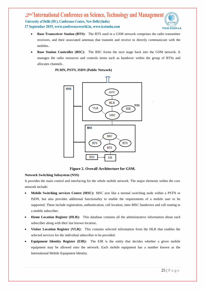
Base Transceiver Station (BTS): The BTS used in a GSM network comprises the radio transmitter
receivers, and their associated antennas that transmit and receive to directly communicate with the
mobiles..
Base Station Controller (BSC): The BSC forms the next stage back into the GSM network. It
manages the radio resources and controls items such as handover within the group of BTSs and
allocates channels .
PLMN, PSTN, ISDN (Public Network)
Figure 2. Overall Architecture for GSM.
Network Switching Subsystem (NSS)
It provides the main control and interfacing for the whole mobile network. The major elements within the core
network include:
Mobile Switching services Centre (MSC): MSC acts like a normal switching node within a PSTN or
ISDN, but also provides additional functionality to enable the requirements of a mobile user to be
supported. These include registration, authentication, call location, inter-MSC handovers and call routing to
a mobile subscriber.
Home Location Register (HLR): This database contains all the administrative information about each
subscriber along with their last known location..
Visitor Location Register (VLR): This contains selected information from the HLR that enables the
selected services for the individual subscriber to be provided.
Equipment Identity Register (EIR): The EIR is the entity that decides whether a given mobile
equipment may be allowed onto the network. Each mobile equipment has a number known as the
International Mobile Equipment Identity.

26 | P a g e
Authentication Centre (AuC): The AuC is a protected database that contains the secret key also
contained in the user's SIM card. It is used for authentication and for ciphering on the radio channel.
Gateway Mobile Switching Centre (GMSC): The GMSC is the point to which a ME terminating call is
initially routed, without any knowledge of the MS's location.
Operation and Support Subsystem (OSS)
The OSS or operation support subsystem is an element within the overall GSM network architecture that is
connected to components of the NSS and the BSC. It is used to control and monitor the overall GSM network
and it is also used to control the traffic load of the BSS.
4.2 IS-95
IS-95 was the first CDMA mobile phone system to gain widespread use and it is found widely in North
America. Its brand name is cdmaOne and the initial specification for the system was IS95A, but its performance
was later upgraded under IS-95B. Apart from voice the mobile phone system is also able to carry data at rates
upto 14.4 kbps for IS-95A and 115 kbps for IS-95B.
IS95 specification summary
PARAMETER DETAILS
Multiple Access Scheme CDMA
Channel bandwidth 1.25 MHz
Data rate 14.4 kbps for IS-95A & 115 kbps for IS-95B
V. THE THIRD GENERATION
Third Generation Technology was developed in order to face up to the new requirements of services what were
coming, as high-quality images and video or to provide access to the Web with higher data rates. The data-
handling capabilities of second-generation systems are limited and was necessary other mobile technology.
Although many proposals were submitted there were several that were considerably more important than others.
These included:
UMTS / WCDMA: The Universal Mobile Telecommunications System using wideband CDMA was the
successor to the highly successful GSM system that was initially deployed around Europe, but was
spreading rapidly worldwide.
CDMA2000: This scheme was the successor to the cdmaOne system defined under Interim Standard IS-95
which was the first system to be deployed using CDMA technology.
5.1 UMTS
UMTS uses Wideband CDMA - WCDMA - as the radio transmission standard. It employs a 5 MHz channel
bandwidth. Using this bandwidth it has the capacity to carry over 100 simultaneous voice calls, or it is able to
carry data at speeds up to 2 Mbps in its original format.. A new introduction for UMTS is that there are
specifications that allow both Frequency Division Duplex (FDD) and Time Division Duplex (TDD) modes.
27 | P a g e
UMTS WCDMA specification summary
The UMTS WCDMA system offered a significant improvement in capability over the previous 2G services.
PARAMETER SPECIFICATION
Data rate 2048 kbps low range, 384 kbps urban and outdoor
RF channel bandwidth 5 MHz
Multiple access scheme CDMA
Duplex schemes FDD and also TDD
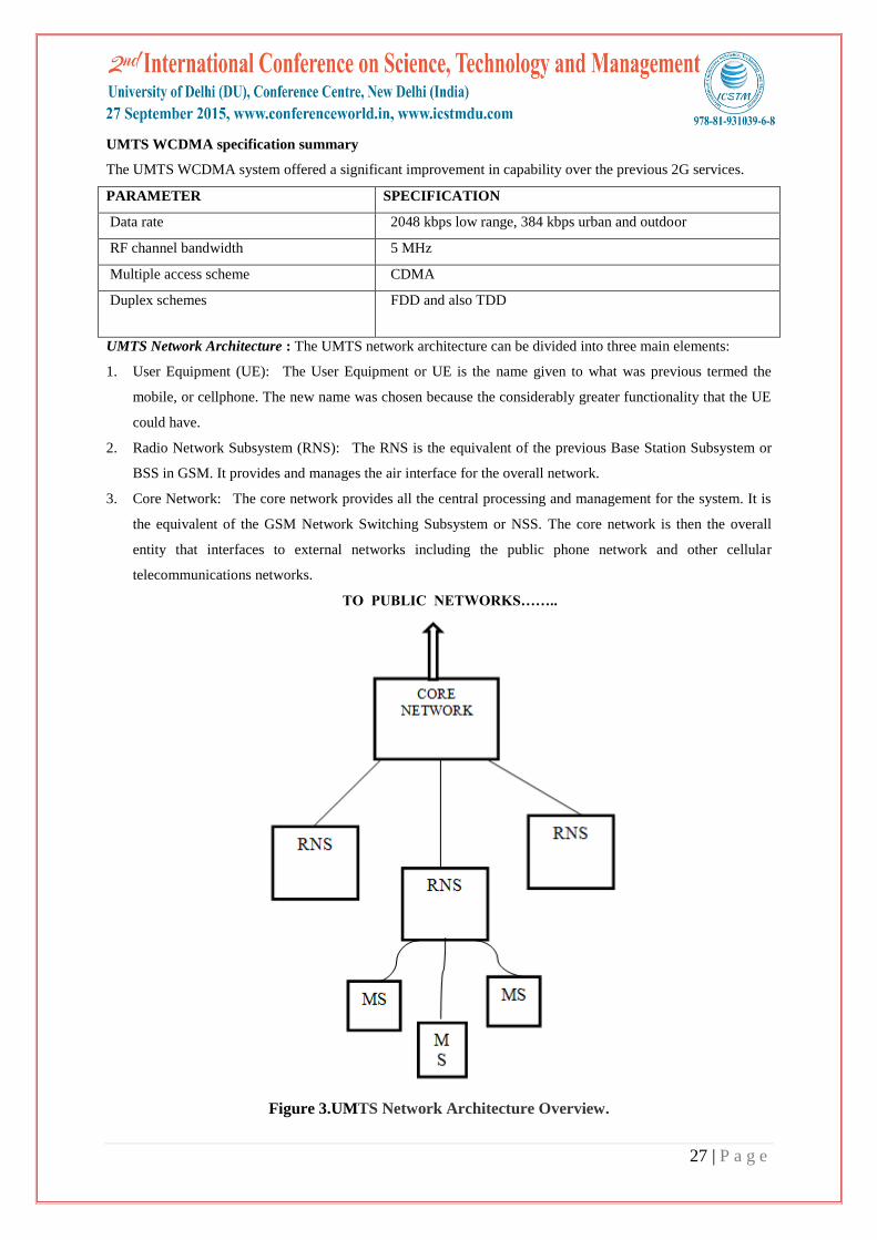
UMTS Network Architecture : The UMTS network architecture can be divided into three main elements:
1. User Equipment (UE): The User Equipment or UE is the name given to what was previous termed the
mobile, or cellphone. The new name was chosen because the considerably greater functionality that the UE
could have.
2. Radio Network Subsystem (RNS): The RNS is the equivalent of the previous Base Station Subsystem or
BSS in GSM. It provides and manages the air interface for the overall network.
3. Core Network: The core network provides all the central processing and management for the system. It is
the equivalent of the GSM Network Switching Subsystem or NSS. The core network is then the overall
entity that interfaces to external networks including the public phone network and other cellular
telecommunications networks.
TO PUBLIC NETWORKS……..
Figure 3.UMTS Network Architecture Overview.

28 | P a g e
5.2 3G LTE Long Term Evolution
LTE, Long Term Evolution, the successor to UMTS and HSPA is now being deployed and is the way forwards
for high speed cellular services. In its first forms it is a 3G or as some would call it a 3.99G technology, but with
further additions the technology can be migrated to a full 4G standard and here it is known as LTE Advanced.
The UMTS cellular technology upgrade has been dubbed LTE - Long Term Evolution. The idea is that 3G LTE
will enable much higher speeds to be achieved along with much lower packet latency.
LTE Network Architecture
The high-level network architecture of LTE is comprised of following three main components:
The User Equipment (UE).
The Evolved UMTS Terrestrial Radio Access Network (E-UTRAN).
The Evolved Packet Core (EPC).
The User Equipment (UE)
The internal architecture of the user equipment for LTE is identical to the one used by UMTS and GSM which
is actually a Mobile Equipment (ME). The mobile equipment comprised of the following important modules:
Mobile Termination (MT): This handles all the communication functions.
Terminal Equipment (TE): This terminates the data streams.
Universal Integrated Circuit Card (UICC): This is also known as the SIM card for LTE equipments. It
runs an application known as the Universal Subscriber Identity Module (USIM).
The E-UTRAN (The access network)
The E-UTRAN handles the radio communications between the mobile and the evolved packet core and just has
one component, the evolved base stations, called eNodeB or eNB. Each eNB is a base station that controls the
mobiles in one or more cells. The base station that is communicating with a mobile is known as its serving eNB.
The Evolved Packet Core (EPC) (The core network)
The evolved packet core communicates with packet data networks in the outside world such as the internet,
private corporate networks or the IP multimedia subsystem. The interfaces between the different parts of the
system are denoted Uu, S1 and SGi as shown in figure:
S1 SGi
Signals
Traffic
Figure 4. LTE Network Architecture Overview.
EU E-UTRAN EPC
Servers
PDNs
29 | P a g e
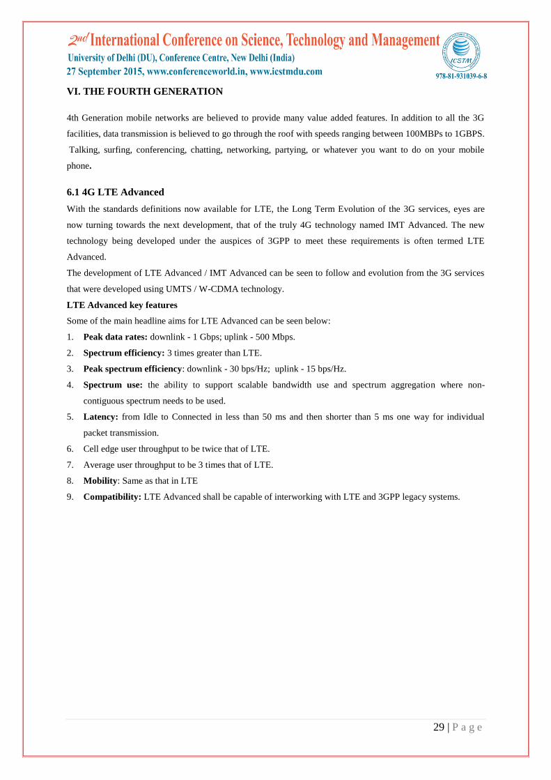
VI. THE FOURTH GENERATION
4th Generation mobile networks are believed to provide many value added features. In addition to all the 3G
facilities, data transmission is believed to go through the roof with speeds ranging between 100MBPs to 1GBPS.
Talking, surfing, conferencing, chatting, networking, partying, or whatever you want to do on your mobile
phone.
6.1 4G LTE Advanced
With the standards definitions now available for LTE, the Long Term Evolution of the 3G services, eyes are
now turning towards the next development, that of the truly 4G technology named IMT Advanced. The new
technology being developed under the auspices of 3GPP to meet these requirements is often termed LTE
Advanced.
The development of LTE Advanced / IMT Advanced can be seen to follow and evolution from the 3G services
that were developed using UMTS / W-CDMA technology.
LTE Advanced key features
Some of the main headline aims for LTE Advanced can be seen below:
1. Peak data rates: downlink - 1 Gbps; uplink - 500 Mbps.
2. Spectrum efficiency: 3 times greater than LTE.
3. Peak spectrum efficiency: downlink - 30 bps/Hz; uplink - 15 bps/Hz.
4. Spectrum use: the ability to support scalable bandwidth use and spectrum aggregation where non-
contiguous spectrum needs to be used.
5. Latency: from Idle to Connected in less than 50 ms and then shorter than 5 ms one way for individual
packet transmission.
6. Cell edge user throughput to be twice that of LTE.
7. Average user throughput to be 3 times that of LTE.
8. Mobility: Same as that in LTE
9. Compatibility: LTE Advanced shall be capable of interworking with LTE and 3GPP legacy systems.

30 | P a g e
Table 1. Comparison Table for Different Generations
Technology 1G 2G 3G 4G
Design Began 1970 1980 1990 2000
Implementation 1981 1991 2001 2010
Services Analog voice Digital voice, short
message
Higher capacity,
data rates up to 2
Mbps
Higher capacity,
completely IP-
Oriented,
multimedia, data to
hundreds of
megabits
Standards AMPS, ETACS, NMT
etc.
TDMA,CDMA,GSM WCDMA,
CDMA-2000
Single standard
Data Rate NA 14.4 kbps 2 Mbps >200 Mbps
Multiplexing FDMA TDMA, CDMA CDMA OFDM
Core Network PSTN PSTN Packet network Internet
Handoff
Horizontal only Horizontal &
Vertical
Horizontal &
Vertical
Horizontal &
Vertical
VII. RADIO OVER FIBER (RoF)
Radio-over-fiber (RoF) technology has emerged as a cost effective approach in which the central site and
multiple number of remote sites are connected by using optical fiber. RoF technology is a technology by which
microwave signals are distributed by means of optical components and techniques. If the application area is in a
„Global System for Mobile communications network, then the central site could be the Mobile Switching
Centre (MSC) and the remote site the base station (BS).. For a multifunctional RoF system, the choice of the
electrical signal at the input depends on the type of functionality of the system. The electrical signal is
modulated with the optical carrier signal. The modulated signal is carried over optical fiber link to the remote
stations. Here, the original data is recovered from the modulated signal by using photo detector. Avalanche
photo detector is commonly used. The benefits of the RoF system are low attenuation loss , large bandwidth,
easy installation and maintenance operational flexibilities. Some of the Rof technology include mobile radio
communication, satellite communications, broadband access Multipoint Video Distribution Services, (MVDS)
Mobile Broadband System (MBS) and wireless LANs over optical networks.
VIII. RADIO OVER FREE SPACE OPTICAL (RoFSO)
Free Space Optics (FSO) is a line of sight technology which involves the transfer of data from one point to
another point using optical radiation in free space . The intensity and phase of the optical carrier signal can be
modulated based on the message signal. FSO provides the flexibility of wireless communication and the speed
of fiber optic communication. An FSO unit consists of optical transceivers with a laser transmitter and a receiver

31 | P a g e
to provide full duplex connectivity between them. Each FSO unit uses a high power opticalsource and a lens that
transmits the lights through the atmosphere to another lens receiving the signal. The advantages of FSO are high
bit rate, ease of deployment, license free operation, high transmission security, full duplex transmission and
protocol transparency. Shielding from electro-magnetic interference should also be mentioned as a significant
advantage in saturated RF spectrum environments. Important features of FSO include huge modulation
bandwidth, narrow beam size, low cost, easy implementation and unlicensed spectrum.
RoFSO is the technology in which it is possible to transmit and receive multiple RF signals simultaneously over
FSO links using wavelength division multiplexing (WDM) technology. RoFSO can be used as a backup of RoF
technology, in case of failure or absence of the fiber network . A simplified block diagram for radio over free
space optical communication system is shown in Figure.
RF OUTPUT SIGNAL
Figure 5. Block Diagram of RoFSO Communication System.
OPTICAL
MODULATOR
TRANSMITTER
FREE SPACE
CHANNEL
RECIEVER
RF INPUT
SIGNAL
OPTICAL
CARRIER
SIGNAL

32 | P a g e
Table 2: Performance Comparison of RoF Using Multimode Optical Fibre and RoFSO as
Signal Distribution Mechanisms.
Parameter RoF RoFSO
Attenuation (electrical)
over 50m
0.1dB 20-40dB
3dB bandwidth over 50m 10GHz possible
(typical commercial
System 3GHz (approx..))
10GHz (limited
by laser)
Maximum range several km 50-100m
Estimate variable cable Cost $0.68/m Nothing
Estimated capital equip-
ment cost
$420 $500 (target)
Estimated installation
Weight
<20kg/m Nothing
Ease of installation Moderate High
Layout exibility Low High
1X. CONCLUSION
This paper given a close survey of development of mobile technologies and also the journey from 1G to
4G.Modern society is increasingly reliant on fast and ubiquitous access to wireless networks. As a result there is
a huge demand on wireless networks and to avoid capacity shortfall, new strategies and technologies must be
developed urgently. Therefore, attention must be turned to the design of wireless delivery infrastructure to
enable further significant improvements in capacity. This is particularly important in indoor environments .
For this problem, the radio-over-fibre (RoF) technology, have been a popular infrastructure solution to improve
coverage for wireless systems. RoF can be extended into RoFSO (Radio on Free Space Optics) which provide a
free space for heterogeneous wireless services in Free Space Optics.
REFERENCES
[1] Rappaport, T.S. Wireless Communications : Principles and Practice. Prentice Hall. Upper Saddle River,
N.J. 1996.
[2] 3GPP, Technical Specification Group Services and System Aspects, Service aspects; Services and Service
Capabilities (Release 99), Report TS 22.105, V3.10.0, Oct. 2001 (http://www.3gpp.org/).
[3] R. Karthikeyan and Dr. S. Prakasam, “A Survey on Radio over Fiber (RoF) for Wireless Broadband
Access Technologies”, International Journal of Computer Applications (0975-8887), Volume 64, No. 12,
February 2013.
[4] Schiller, J. “Mobile Communications”. Ed. Addison-Wesley.
[5] Sesia,S. Toufik,I. and Baker,M. ,” LTE – The UMTS Long Term Evolution” Second Edition.