a first look at applications and the icofoam/cavity work...
TRANSCRIPT

CFD with OpenSource Software, 2015
©Håkan Nilsson, Chalmers / Applied Mechanics / Fluid Dynamics 1
A first look at applications
and the icoFoam/cavity work procedure
CFD with OpenSource Software, 2015
©Håkan Nilsson, Chalmers / Applied Mechanics / Fluid Dynamics 2
Applications: Solvers and Utilities
• OpenFOAM is first and foremost a C++ library, used primarily
to create executables, known as applications. The applications
fall into two categories: solvers, that are each designed to solve
a specific continuum mechanics problem; and utilities, that are de-
signed to perform tasks that involve data manipulation.
• Special applications for pre- and post-processing are included in
OpenFOAM. Converters to/from other pre- and post-processors are
available.
• OpenFOAM is distributed with a large number of applications, but
soon any advanced user will start developing new applications for
his/ her special needs. The basic way to do this is to find and copy
an application that almost does what is needed, and then to modify
it by copy/paste from other applications that has some features
that are needed.
We will now have a look at how to use this in practice. NOTE that the output of the commands
in the following slides might not be exactly the same in all versions of OpenFOAM, but the
general procedures are the same.

CFD with OpenSource Software, 2015
©Håkan Nilsson, Chalmers / Applied Mechanics / Fluid Dynamics 3
The icoFoam/cavity tutorial
• Basic procedure when running a tutorial, in this case icoFoam/cavity:
cp -r $FOAM_TUTORIALS/incompressible/icoFoam/cavity $FOAM_RUN
run
cd cavity
You have copied the cavity tutorial and moved to $FOAM_RUN/cavity
• The mesh is defined by a dictionary that is read by the blockMesh utility
blockMesh
You have now generated the mesh in OpenFOAM format. Check the output from blockMesh!
• Check the mesh by
checkMesh
You see the mesh size, the geometrical size and some mesh checks (e.g. cell volumes).
• This is a case for the icoFoam solver, so run
icoFoam >& log&
You now ran the simulation in background using the settings in the case, and forwarded
the errors and standard output to the $FOAM_RUN/cavity/log file, where the Courant
numbers and the residuals are shown.

CFD with OpenSource Software, 2015
©Håkan Nilsson, Chalmers / Applied Mechanics / Fluid Dynamics 4
Application parameters
Most OpenFOAM applications take parameters. Use the -help flag to get info:
• blockMesh -help
(do it and look at the output in the terminal window)
The [-case dir] is the most common one, and with that you can specify the path to
the case directory if you do not want to move to that case directory.
• checkMesh -help
(do it and look at the output in the terminal window)
• icoFoam -help
(do it and look at the output in the terminal window)

CFD with OpenSource Software, 2015
©Håkan Nilsson, Chalmers / Applied Mechanics / Fluid Dynamics 5
A graphical view of the icoFoam/cavity tutorial
• We will now have a quick look at the results using paraFoam:
paraFoam
Click on ’Last Frame’:
Click Apply.
Color by Pressure using Display/Color by
Move, rotate and scale the visualization using the mouse
• We will learn how to use paraFoam more further on.
• Exit paraFoam: File/Exit
• The results may also be viewed using third-party products:
foamToEnsight etc., type: foamTo[TAB] to see alternatives.
There is also a direct reader for Ensight - see the UserGuide.
• For post-processing in Fluent, run:
foamMeshToFluent, and foamDataToFluent (controlDict is
used to specify the time step, and a foamDataToFluentDict dic-
tionary is required - see the UserGuide).
CFD with OpenSource Software, 2015
©Håkan Nilsson, Chalmers / Applied Mechanics / Fluid Dynamics 6
icoFoam/cavity tutorial - What did we do?
• We will have a look at what we did when running the cavity
tutorial by looking at the case files.
• First of all it should be noted that icoFoam is a Transient solver
for incompressible, laminar flow of Newtonian fluids
• The case directory originally contains the following sub-directories:
0, constant, and system. After our run it also contains the out-
put 0.1, 0.2, 0.3, 0.4, 0.5, and log
• The 0* directories contain the values of all the variables at those
time steps. The 0 directory is thus the initial condition.
• The constant directory contains the mesh and a transportProperties
dictionary for the kinematic viscosity.
• The system directory contains settings for the run, discretization
schemes, and solution procedures.
• The icoFoam solver reads the files in the case directory and runs
the case according to those settings.
CFD with OpenSource Software, 2015
©Håkan Nilsson, Chalmers / Applied Mechanics / Fluid Dynamics 7
icoFoam/cavity tutorial - The constant directory
• The constant/transportProperties file is a dictionary for the dimen-
sioned scalar nu.
• The polyMesh directory originally contains the blockMeshDict dictio-
nary for the blockMesh mesh generator, and now also the mesh in Open-
FOAM format.
• We will now have a quick look at the blockMeshDict dictionary in order
to understand what mesh we have used.
CFD with OpenSource Software, 2015
©Håkan Nilsson, Chalmers / Applied Mechanics / Fluid Dynamics 8
icoFoam/cavity tutorial - blockMeshDict dictionary
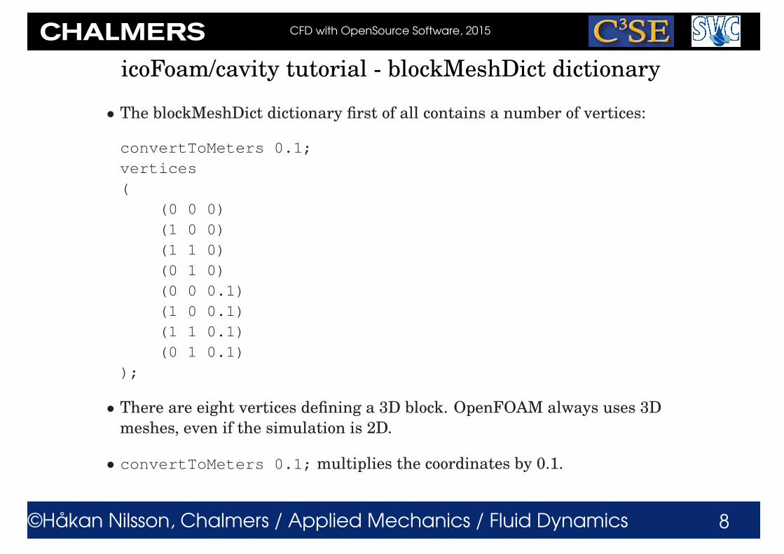
• The blockMeshDict dictionary first of all contains a number of vertices:
convertToMeters 0.1;
vertices
(
(0 0 0)
(1 0 0)
(1 1 0)
(0 1 0)
(0 0 0.1)
(1 0 0.1)
(1 1 0.1)
(0 1 0.1)
);
• There are eight vertices defining a 3D block. OpenFOAM always uses 3D
meshes, even if the simulation is 2D.
• convertToMeters 0.1; multiplies the coordinates by 0.1.
CFD with OpenSource Software, 2015
©Håkan Nilsson, Chalmers / Applied Mechanics / Fluid Dynamics 9
icoFoam/cavity tutorial - blockMeshDict dictionary
• The blockMeshDict dictionary secondly defines a block and the mesh from
the vertices:
blocks
(
hex (0 1 2 3 4 5 6 7) (20 20 1) simpleGrading (1 1 1)
);
• hex means that it is a structured hexahedral block.
• (0 1 2 3 4 5 6 7) is the vertices used to define the block. The order
of these is important - they should form a right-hand system! See the
UserGuide.
• (20 20 1) is the number of mesh cells in each direction.
• simpleGrading (1 1 1) is the expansion ratio, in this case equidis-
tant. The numbers are the ratios between the end cells along three edges.
See the UserGuide.

CFD with OpenSource Software, 2015
©Håkan Nilsson, Chalmers / Applied Mechanics / Fluid Dynamics 10
icoFoam/cavity tutorial - blockMeshDict dictionary
The blockMeshDict dictionary finally defines three patches:
boundary
(
movingWall
{
type wall;
faces
(
(3 7 6 2)
);
}
fixedWalls
{
type wall;
faces
(
(0 4 7 3)
(2 6 5 1)
(1 5 4 0)
);
}
frontAndBack
{
type empty;
faces
(
(0 3 2 1)
(4 5 6 7)
);
}
);
CFD with OpenSource Software, 2015
©Håkan Nilsson, Chalmers / Applied Mechanics / Fluid Dynamics 11
icoFoam/cavity tutorial - blockMeshDict dictionary
• Each patch defines a type, a name, and a list of boundary faces
• Let’s have a look at the fixedWalls patch:
fixedWalls{
type wall;
faces
(
(0 4 7 3)
(2 6 5 1)
(1 5 4 0)
);}
• wall is the type of the boundary.
• fixedWalls is the name of the patch.
• The patch is defined by three sides of the block according to the list, which
refers to the vertex numbers. The order of the vertex numbers is such that
they are marched clock-wise when looking from inside the block. This is
important, and unfortunately checkMesh will not check this.
CFD with OpenSource Software, 2015
©Håkan Nilsson, Chalmers / Applied Mechanics / Fluid Dynamics 12
icoFoam/cavity tutorial - blockMeshDict dictionary
• There are two empty sub-dictionaries in the icoFoam/cavity tutorial:
edges();
mergePatchPairs();
• edges(); is used to define shapes of the edges if they are not straight
- polySpline, polyLine, line, simpleSpline, arc. We will use arc
later on.
• mergePatchPairs(); is used to stitch two blocks that are not connected,
but share the same physical surface at a patch of each block. This means
that both blocks have a patch which is defined with four vertices in the
same location as the corresponding patch in the neighbouring block, but
the vertices are not the same in both blocks. It should be possible to stitch
non-conformal meshes so the number of nodes and the distribution of the
nodes do not have to be the same on both sides. This can also be done for
two separate meshes, using the stitchMesh utility. We will do that later.

CFD with OpenSource Software, 2015
©Håkan Nilsson, Chalmers / Applied Mechanics / Fluid Dynamics 13
icoFoam/cavity tutorial - blockMeshDict dictionary
• To sum up, the blockMeshDict dictionary generates a block with:
x/y/z dimensions 0.1/0.1/0.01
20×20×1 cells
wall fixedWalls patch at three sides
wall movingWall patch at one side
empty frontAndBack patch at two sides
• The type empty tells OpenFOAM that it is a 2D case, i.e. the equations
will not be solved for in the direction of the empty patches. In fact, the
discretization will explicitly neglect the third direction, which makes the
numerical problem purely 2D.
• Read more about blockMesh yourself in the UserGuide.
• You can also convert mesh files from third-party products - see the User-
Guide. If you use ICEM, a good procedure is to write a Fluent mesh file
(*.msh) and convert it with fluentMeshToFoam or fluent3DMeshToFoam.
CFD with OpenSource Software, 2015
©Håkan Nilsson, Chalmers / Applied Mechanics / Fluid Dynamics 14
icoFoam/cavity tutorial - the mesh
• blockMesh uses the blockMeshDict to generate some files in the
constant/polyMesh directory:
boundary faces neighbour owner points
• In the following slides we will discuss them...

CFD with OpenSource Software, 2015
©Håkan Nilsson, Chalmers / Applied Mechanics / Fluid Dynamics 15
icoFoam/cavity tutorial - the boundary file
• The boundary file shows the definitions of the patches, for instance:
movingWall
{
type wall;
inGroups 1(wall);
nFaces 20;
startFace 760;
}
• The faces are numbered, starting with the internal faces, following with
the boundary faces. That is why the first patch starts with face 760.
• The movingWall patch has 20 faces, and the next patch starts at face
780.
• Each patch can be put inGroups for pre- and post-processing purpose.
Each patch can thus be in several groups. The patchGroup generated
by this makes e.g. setting of boundary conditions easier. A patch bound-
ary condition definition takes precedence over a patchGroup boundary
condition. The patchGroups are also listed in paraFoam.

CFD with OpenSource Software, 2015
©Håkan Nilsson, Chalmers / Applied Mechanics / Fluid Dynamics 16
icoFoam/cavity tutorial - the points file
• The points file shows the positions of all the points in the mesh:
882
(
(0 0 0)
(0.005 0 0)
(0.01 0 0)
(0.015 0 0)
...
)
• There are 882 points in this case.
• The points have an internal number: 0, 1, 2, ..., 881
CFD with OpenSource Software, 2015
©Håkan Nilsson, Chalmers / Applied Mechanics / Fluid Dynamics 17
icoFoam/cavity tutorial - the faces file
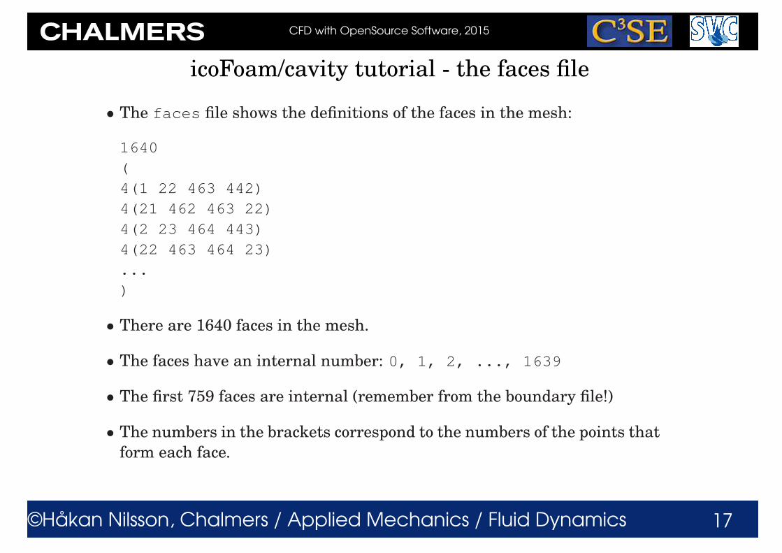
• The faces file shows the definitions of the faces in the mesh:
1640
(
4(1 22 463 442)
4(21 462 463 22)
4(2 23 464 443)
4(22 463 464 23)
...
)
• There are 1640 faces in the mesh.
• The faces have an internal number: 0, 1, 2, ..., 1639
• The first 759 faces are internal (remember from the boundary file!)
• The numbers in the brackets correspond to the numbers of the points that
form each face.
CFD with OpenSource Software, 2015
©Håkan Nilsson, Chalmers / Applied Mechanics / Fluid Dynamics 18
icoFoam/cavity tutorial - the owner file
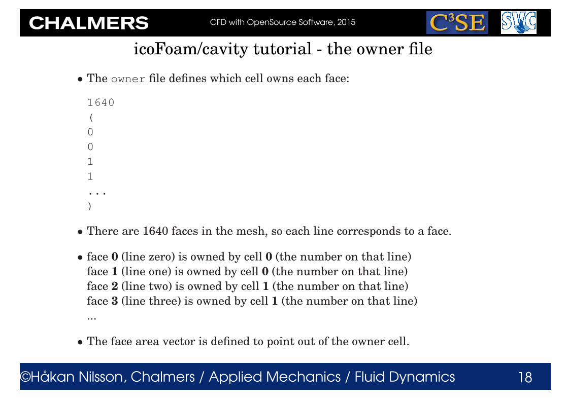
• The owner file defines which cell owns each face:
1640
(
0
0
1
1
...
)
• There are 1640 faces in the mesh, so each line corresponds to a face.
• face 0 (line zero) is owned by cell 0 (the number on that line)
face 1 (line one) is owned by cell 0 (the number on that line)
face 2 (line two) is owned by cell 1 (the number on that line)
face 3 (line three) is owned by cell 1 (the number on that line)
...
• The face area vector is defined to point out of the owner cell.

CFD with OpenSource Software, 2015
©Håkan Nilsson, Chalmers / Applied Mechanics / Fluid Dynamics 19
icoFoam/cavity tutorial - the neighbour file
• The neighbour file defines which cell is the neighbour of the owner of
each face:
760
(
1
20
2
21 ...
)
• There are 760 internal faces in the mesh. The boundary faces only have
an owner cell.
• face 0 is owned by cell 0 (as before), and cell 1 is the neighbouring cell
face 1 is owned by cell 0 (as before), and cell 20 is the neighbouring cell
face 2 is owned by cell 1 (as before), and cell 2 is the neighbouring cell
face 3 is owned by cell 1 (as before), and cell 21 is the neighbouring cell
...
• The face area vector is defined to point into the neighbour cell.

CFD with OpenSource Software, 2015
©Håkan Nilsson, Chalmers / Applied Mechanics / Fluid Dynamics 20
icoFoam/cavity tutorial - The system directory
• The system directory consists of three set-up files:
controlDict fvSchemes fvSolution
• controlDict contains general instructions on how to run the case.
• fvSchemes contains instructions on which discretization schemes that
should be used for different terms in the equations.
• fvSolution contains instructions on how to solve each discretized lin-
ear equation system. It also contains instructions for the PISO pressure-
velocity coupling.

CFD with OpenSource Software, 2015
©Håkan Nilsson, Chalmers / Applied Mechanics / Fluid Dynamics 21
icoFoam/cavity tutorial - The controlDict dictionary
• The controlDict dictionary consists of the following lines:
application icoFoam;
startFrom startTime;
startTime 0;
stopAt endTime;
endTime 0.5;
deltaT 0.005;
writeControl timeStep;
writeInterval 20;
purgeWrite 0;
writeFormat ascii;
writePrecision 6;
writeCompression off;
timeFormat general;
timePrecision 6;
runTimeModifiable true;

CFD with OpenSource Software, 2015
©Håkan Nilsson, Chalmers / Applied Mechanics / Fluid Dynamics 22
icoFoam/cavity tutorial - The controlDict dictionary
• application icoFoam;
Was previously used to tell the GUI FoamX in OpenFOAM-1.4.1 (and ear-
lier) to use the set-up specifications of the icoFoam solver.
Is used for the Allrun scripts in the tutorials directory, but it will not influ-
ence the solution as long as you manually start the case with the correct
solver.
• The following lines tells icoFoam to start at startTime=0, and stop at
endTime=0.5, with a time step deltaT=0.005:
startFrom startTime;
startTime 0;
stopAt endTime;
endTime 0.5;
deltaT 0.005;

CFD with OpenSource Software, 2015
©Håkan Nilsson, Chalmers / Applied Mechanics / Fluid Dynamics 23
icoFoam/cavity tutorial - The controlDict dictionary
• The following lines tells icoFoam to write out results in separate di-
rectories (purgeWrite 0;) every 20 timeStep, and that they should
be written in uncompressed ascii format with writePrecision 6.
timeFormat and timePrecision are instructions for the names of the
time directories.
writeControl timeStep;
writeInterval 20;
purgeWrite 0;
writeFormat ascii;
writePrecision 6;
writeCompression off;
timeFormat general;
timePrecision 6;
I recommend the use of writeCompression on; and writeFormat ascii;,
which does not fill up your hard drive, and you can still open the files with
vim. For fine dynamic meshes, it is recommended to use the binary for-
mat, to avoid deterioration of the mesh.

CFD with OpenSource Software, 2015
©Håkan Nilsson, Chalmers / Applied Mechanics / Fluid Dynamics 24
icoFoam/cavity tutorial - The controlDict dictionary
• runTimeModifiable true; allows you to make modifications to the
case while it is running.

CFD with OpenSource Software, 2015
©Håkan Nilsson, Chalmers / Applied Mechanics / Fluid Dynamics 25
Specifying a maximum Courant number and varying time steps
• Some solvers, like the interFoam solver allows a varying time step, based
on a maximum Courant number. Some extra entries should then be added
to the controlDict dictionary:
adjustTimeStep on;
maxCo 0.5;
maxAlphaCo 0.2;
maxDeltaT 1;
• The solver is then told to adjust the time step so that the output still
occurs at specific times using:
writeControl adjustableRunTime;
writeInterval 0.05;

CFD with OpenSource Software, 2015
©Håkan Nilsson, Chalmers / Applied Mechanics / Fluid Dynamics 26
icoFoam/cavity tutorial - A dictionary hint
• If you don’t know which entries are available for a specific key word in a
dictionary, just use a dummy and the solver will list the alternatives, for
instance:
stopAt dummy;
When running icoFoam you will get the message:
dummy is not in enumeration
4
(
endTime
writeNow
noWriteNow
nextWrite
)
and you will know the alternatives.
This does not work for all entries for some reason. In some cases, a mes-
sage is written and a default value is used. Check the log file!
CFD with OpenSource Software, 2015
©Håkan Nilsson, Chalmers / Applied Mechanics / Fluid Dynamics 27
icoFoam/cavity tutorial - More dictionary hints
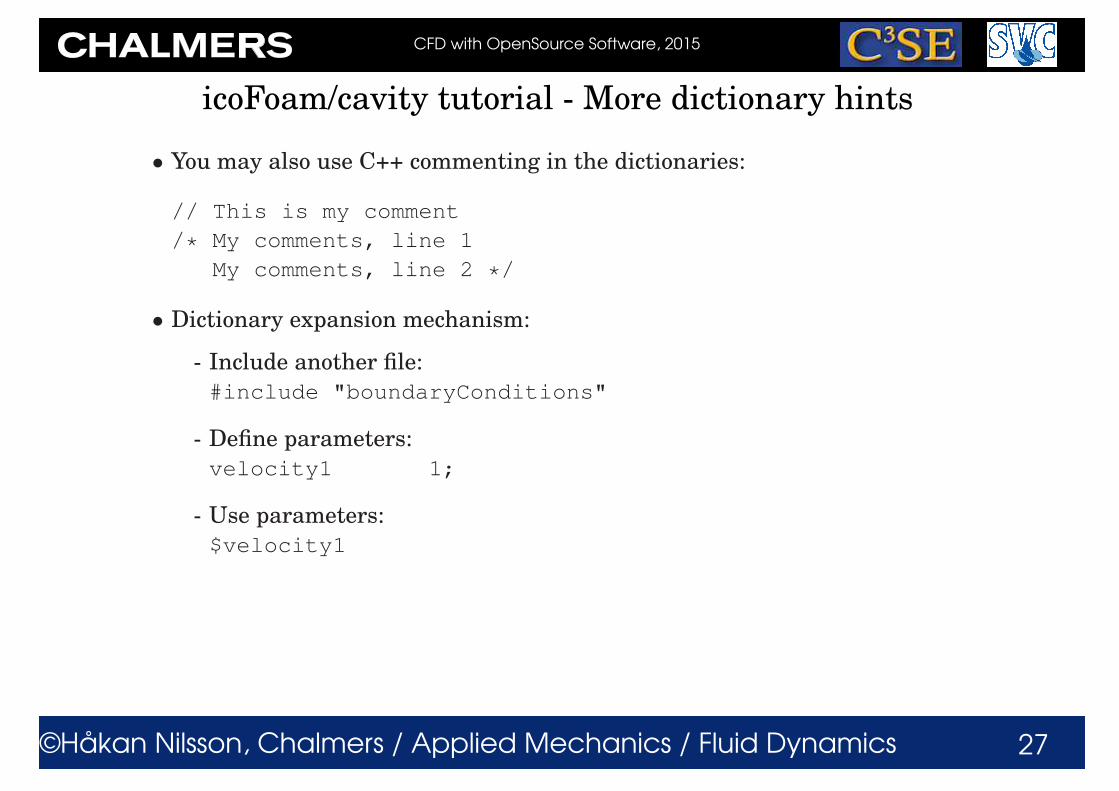
• You may also use C++ commenting in the dictionaries:
// This is my comment
/* My comments, line 1
My comments, line 2 */
• Dictionary expansion mechanism:
- Include another file:
#include "boundaryConditions"
- Define parameters:
velocity1 1;
- Use parameters:
$velocity1
CFD with OpenSource Software, 2015
©Håkan Nilsson, Chalmers / Applied Mechanics / Fluid Dynamics 28
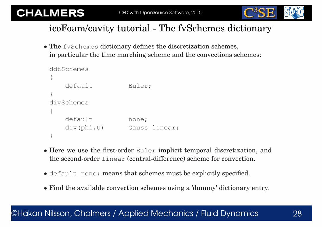
icoFoam/cavity tutorial - The fvSchemes dictionary
• The fvSchemes dictionary defines the discretization schemes,
in particular the time marching scheme and the convections schemes:
ddtSchemes
{
default Euler;
}
divSchemes
{
default none;
div(phi,U) Gauss linear;
}
• Here we use the first-order Euler implicit temporal discretization, and
the second-order linear (central-difference) scheme for convection.
• default none; means that schemes must be explicitly specified.
• Find the available convection schemes using a ’dummy’ dictionary entry.

CFD with OpenSource Software, 2015
©Håkan Nilsson, Chalmers / Applied Mechanics / Fluid Dynamics 29
icoFoam/cavity tutorial - The fvSolution dictionary
• The fvSolution dictionary defines the solution procedure.
• The solutions of the p linear equation systems is defined by:
p
{
solver PCG;
preconditioner DIC;
tolerance 1e-06;
relTol 0;
}
• The p linear equation system is solved using PCG (see later), with the DIC
preconditioner (see later).
• The solution is considered converged when the residual has reached the
tolerance, or if it has been reduced by relTol at each time step.
• relTol is here set to zero since we use the PISO algorithm. The PISO al-
gorithm only solves each equation once per time step, and we should thus
solve the equations to tolerance 1e-06 at each time step. relTol 0;
disables relTol.
CFD with OpenSource Software, 2015
©Håkan Nilsson, Chalmers / Applied Mechanics / Fluid Dynamics 30
icoFoam/cavity tutorial - The fvSolution dictionary
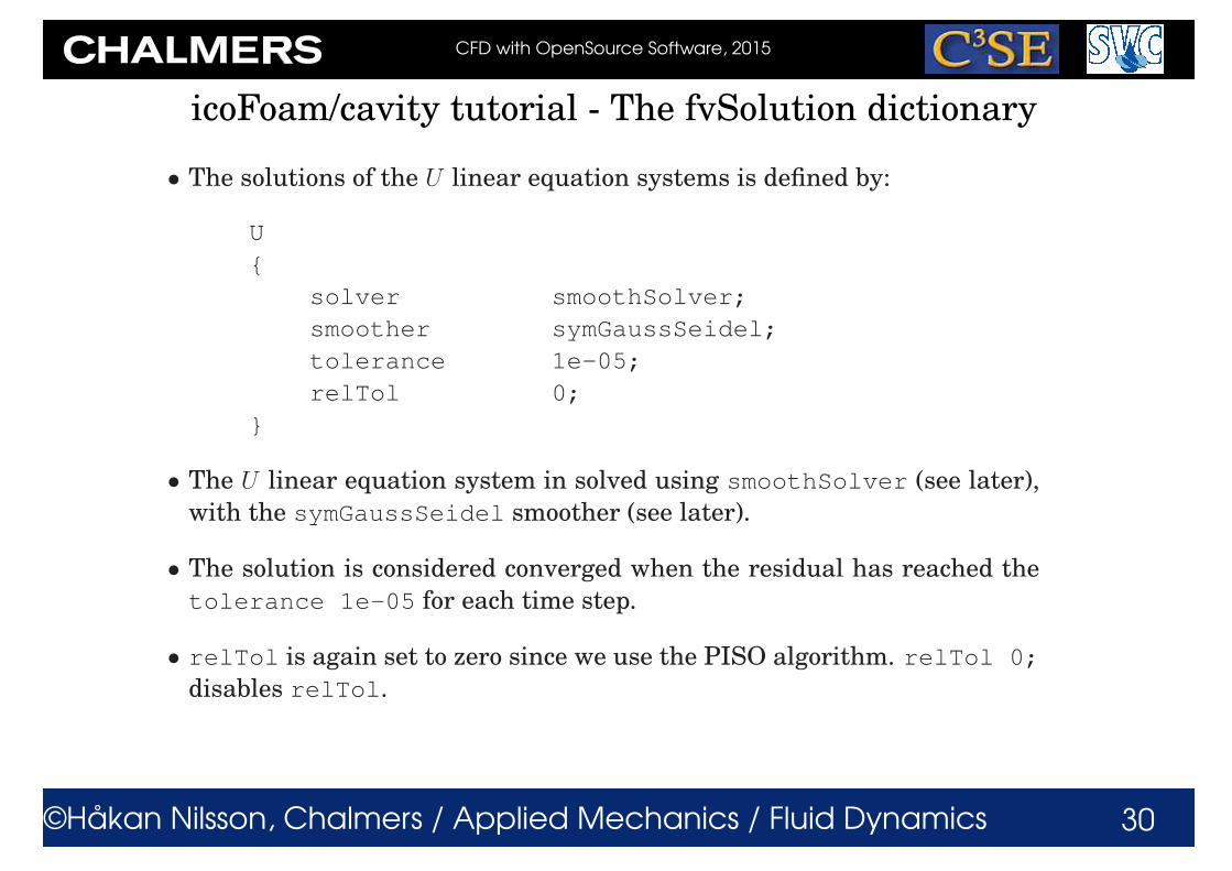
• The solutions of the U linear equation systems is defined by:
U
{
solver smoothSolver;
smoother symGaussSeidel;
tolerance 1e-05;
relTol 0;
}
• The U linear equation system in solved using smoothSolver (see later),
with the symGaussSeidel smoother (see later).
• The solution is considered converged when the residual has reached the
tolerance 1e-05 for each time step.
• relTol is again set to zero since we use the PISO algorithm. relTol 0;
disables relTol.

CFD with OpenSource Software, 2015
©Håkan Nilsson, Chalmers / Applied Mechanics / Fluid Dynamics 31
Main linear solvers
See:
http://www.tfd.chalmers.se/~hani/kurser/OS_CFD_2008/TimBehrens/tibeh-report-fin.pdf
http://www-users.cs.umn.edu/~saad/books.html
and descriptions using:
emacs $FOAM_SRC/OpenFOAM/matrices/lduMatrix/solvers/*/*.H)
• GAMG - Geometric agglomerated algebraic multigrid solver (also named
Generalised geometric-algebraic multi-grid in the manual)
• PBiCG - Preconditioned bi-conjugate gradient solver for asymmetric ldu-
Matrices using a run-time selectable preconditioner
• PCG - Preconditioned conjugate gradient solver for symmetric lduMatrices
using a run-timeselectable preconditiioner
• smoothSolver - Iterative solver using smoother for symmetric and asym-
metric matrices which uses a run-time selected smoother, e.g. Gauss-
Seidel.

CFD with OpenSource Software, 2015
©Håkan Nilsson, Chalmers / Applied Mechanics / Fluid Dynamics 32
Preconditioners (1/2)
See:
http://www.tfd.chalmers.se/~hani/kurser/OS_CFD_2008/TimBehrens/tibeh-report-fin.pdf
and descriptions using:
emacs $FOAM_SRC/OpenFOAM/matrices/lduMatrix/preconditioners/*/*.H)
• diagonalPreconditioner - Diagonal preconditioner for both symmet-
ric and asymmetric matrices. This preconditioner actually does not help
with faster propagation through the grid, but it is very easy and can be
a good first step. Note: The reciprocal of the diagonal is calculated and
stored for reuse because on most systems multiplications are faster than
divisions.
• DICPreconditioner - Simplified diagonal-based incomplete Cholesky
preconditioner for symmetric matrices (symmetric equivalent of DILU).
The reciprocal of the preconditioned diagonal is calculated and stored.
• DILUPreconditioner - Simplified diagonal-based incomplete LU pre-
conditioner for asymmetric matrices. The reciprocal of the preconditioned
diagonal is calculated and stored.

CFD with OpenSource Software, 2015
©Håkan Nilsson, Chalmers / Applied Mechanics / Fluid Dynamics 33
Preconditioners (2/2)
• FDICPreconditioner - Faster version of the DICPreconditioner diagonal-
based incomplete Cholesky preconditioner for symmetric matrices (sym-
metric equivalent of DILU) in which the reciprocal of the preconditioned
diagonal and the upper coeffcients divided by the diagonal are calculated
and stored.
• GAMGPreconditioner - Geometric agglomerated algebraic multigrid pre-
conditioner (also named Generalised geometric-algebraic multi-grid in the
manual).
• noPreconditioner - Null preconditioner for both symmetric and asym-
metric matrices.

CFD with OpenSource Software, 2015
©Håkan Nilsson, Chalmers / Applied Mechanics / Fluid Dynamics 34
Smoothers (1/2)
See:
http://www.tfd.chalmers.se/~hani/kurser/OS_CFD_2008/TimBehrens/tibeh-report-fin.pdf
and descriptions using:
emacs $FOAM_SRC/OpenFOAM/matrices/lduMatrix/smoothers/*/*.H)
• DIC - Simplified diagonal-based incomplete Cholesky smoother for sym-
metric matrices.
• DICGaussSeidel - Combined DIC/GaussSeidel smoother for symmetric
matrices in which DIC smoothing is followed by GaussSeidel to ensure
that any "spikes" created by the DIC sweeps are smoothed-out.
• DILU - Simplified diagonal-based incomplete LU smoother for asymmetric
matrices. ILU smoothers are good smoothers for linear multigrid meth-
ods.
• DILUGaussSeidel - Combined DILU/GaussSeidel smoother for asym-
metric matrices in which DILU smoothing is followed by GaussSeidel to
ensure that any "spikes" created by the DILU sweeps are smoothed-out.

CFD with OpenSource Software, 2015
©Håkan Nilsson, Chalmers / Applied Mechanics / Fluid Dynamics 35
Smoothers (2/2)
• GaussSeidel - The GaussSeidel method is a technique used to solve a
linear system of equations. The method is an improved version of the
Jacobi method. It is defined on matrices with non-zero diagonals, but con-
vergence is only guaranteed if the matrix is either diagonally dominant,
or symmetric and positive definite.
• symGaussSeidel, nonBlockingGaussSeidel, FDIC
CFD with OpenSource Software, 2015
©Håkan Nilsson, Chalmers / Applied Mechanics / Fluid Dynamics 36
icoFoam/cavity tutorial - The fvSolution dictionary
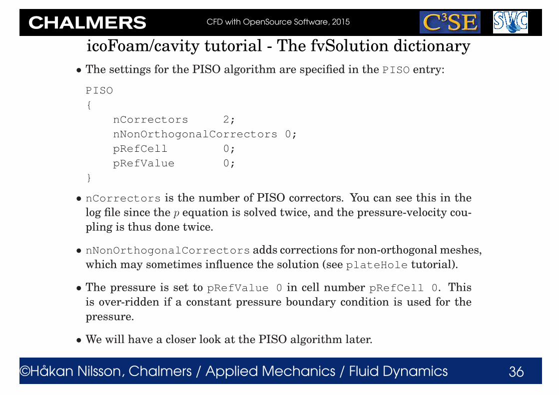
• The settings for the PISO algorithm are specified in the PISO entry:
PISO
{
nCorrectors 2;
nNonOrthogonalCorrectors 0;
pRefCell 0;
pRefValue 0;
}
• nCorrectors is the number of PISO correctors. You can see this in the
log file since the p equation is solved twice, and the pressure-velocity cou-
pling is thus done twice.
• nNonOrthogonalCorrectors adds corrections for non-orthogonal meshes,
which may sometimes influence the solution (see plateHole tutorial).
• The pressure is set to pRefValue 0 in cell number pRefCell 0. This
is over-ridden if a constant pressure boundary condition is used for the
pressure.
• We will have a closer look at the PISO algorithm later.

CFD with OpenSource Software, 2015
©Håkan Nilsson, Chalmers / Applied Mechanics / Fluid Dynamics 37
icoFoam/cavity tutorial - The 0 directory
• The 0 directory contains the dimensions, and the initial and boundary
conditions for all primary variables, in this case p and U. U-example:
dimensions [0 1 -1 0 0 0 0];
internalField uniform (0 0 0);
boundaryField
{ movingWall
{
type fixedValue;
value uniform (1 0 0);
}
fixedWalls
{
type fixedValue;
value uniform (0 0 0);
}
frontAndBack
{
type empty;
}}

CFD with OpenSource Software, 2015
©Håkan Nilsson, Chalmers / Applied Mechanics / Fluid Dynamics 38
icoFoam/cavity tutorial - The 0 directory
• dimensions [0 1 -1 0 0 0 0]; states that the dimension of U is m/s.
We will have a further look at this later on.
• internalField uniform (0 0 0); sets U to zero internally.
• The boundary patches movingWall and fixedWalls are given the
type fixedValue; value uniform (1 0 0); and (0 0 0) respec-
tively, i.e. Ux = 1m/s, and U = 0m/s respectively.
• The frontAndBack patch is given type empty;, indicating that no so-
lution is required in that direction since the case is 2D.
• You should now be able to understand 0/p also.
• The resulting 0.* directories are similar but the internalField is now
a nonuniform List<vector> containing the results. Some boundary
condition types also give nonuniform List. There is also a phi file, con-
taining the resulting face fluxes that are needed to give a perfect restart.
There is also some time information in 0.*/uniform/time. The 0.*/uniform
directory is used for uniform information in a parallel simulation.
CFD with OpenSource Software, 2015
©Håkan Nilsson, Chalmers / Applied Mechanics / Fluid Dynamics 39
icoFoam/cavity tutorial - The log file
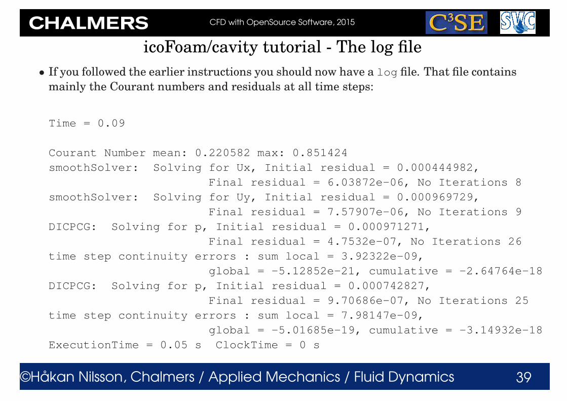
• If you followed the earlier instructions you should now have a log file. That file contains
mainly the Courant numbers and residuals at all time steps:
Time = 0.09
Courant Number mean: 0.220582 max: 0.851424
smoothSolver: Solving for Ux, Initial residual = 0.000444982,
Final residual = 6.03872e-06, No Iterations 8
smoothSolver: Solving for Uy, Initial residual = 0.000969729,
Final residual = 7.57907e-06, No Iterations 9
DICPCG: Solving for p, Initial residual = 0.000971271,
Final residual = 4.7532e-07, No Iterations 26
time step continuity errors : sum local = 3.92322e-09,
global = -5.12852e-21, cumulative = -2.64764e-18
DICPCG: Solving for p, Initial residual = 0.000742827,
Final residual = 9.70686e-07, No Iterations 25
time step continuity errors : sum local = 7.98147e-09,
global = -5.01685e-19, cumulative = -3.14932e-18
ExecutionTime = 0.05 s ClockTime = 0 s
CFD with OpenSource Software, 2015
©Håkan Nilsson, Chalmers / Applied Mechanics / Fluid Dynamics 40
icoFoam/cavity tutorial - The log file
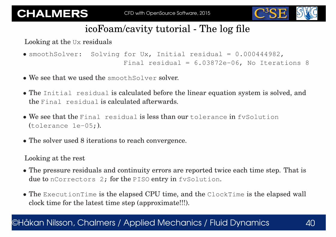
Looking at the Ux residuals
• smoothSolver: Solving for Ux, Initial residual = 0.000444982,
Final residual = 6.03872e-06, No Iterations 8
• We see that we used the smoothSolver solver.
• The Initial residual is calculated before the linear equation system is solved, and
the Final residual is calculated afterwards.
• We see that the Final residual is less than our tolerance in fvSolution
(tolerance 1e-05;).
• The solver used 8 iterations to reach convergence.
Looking at the rest
• The pressure residuals and continuity errors are reported twice each time step. That is
due to nCorrectors 2; for the PISO entry in fvSolution.
• The ExecutionTime is the elapsed CPU time, and the ClockTime is the elapsed wall
clock time for the latest time step (approximate!!!).

CFD with OpenSource Software, 2015
©Håkan Nilsson, Chalmers / Applied Mechanics / Fluid Dynamics 41
icoFoam/cavity tutorial - Plot residuals
• It is of interest to have a graphical representation of the residual development.
• The foamLog utility is basically a script using grep, awk and sed to extract values from
a log file. See $WM_PROJECT_DIR/bin/foamLog for the source code.
• foamLog uses a database (foamLog.db) to know what to extract. The foamLog.db
database can be modified if you want to extract any other values that foamLog doesn’t
extract by default. (find $WM_PROJECT_DIR -iname "*foamLog.db*", or see the
top of the output of foamLog, and make your own copy to modify in
$HOME/.OpenFOAM/2.4.x/foamLog.db, which will be used automatically. Instruc-
tions are available in the foamLog.db file.)
• foamLog is executed on the cavity case with log-file log by:
foamLog log
• A directory logs has now been generated, with extracted values in ascii format in two
columns. The first column is the Time, and the second column is the value at that time.
• Type foamLog -h for more information.
• The graphical representation is then given by Matlab, xmgrace -log y Ux_0 p_0 or
gnuplot: set logscale y, plot "Ux_0","Uy_0","p_0".
• You can also use the user-contributed pyFoam to plot residuals on-the-fly (later).