a secured enterprise network using hierarchical network
TRANSCRIPT
Journal of Newviews in Engineering and Technology (JNET)
Available online at http://www.rsujnet.org/index.php/publications/2019
Copyright © 2019 JNET
A Secured Enterprise Model and Artificial Neural Network: A Case Study of
Engineering,
Joseph D. Enoch,Department of Electrical and Computer Engi
E-mail of the corresponding author:
ABSTRACT This paper presents specifications and design
secure, scalable, available, and manageable hnetwork for Faculty of Engineering,University, Port Harcourt, Nigeria. The Network prototype was designed to includeservices that consist of an enterprise network as a unit. In addition, Artificial Neural Network technique develop a unique encryption key as an additional security for the Faculty database. Furthermore, the physical and logical network topology of the Faculty of Engineering, were successfully designedspecifications from the design was used to configure network devices, servers and security features. outcome of the design was estimated to reduced network device load and the time to identify and resolve issues by a ratio of 1:8. Moreover, the odesign also enhanced rapid connectivity, and of new devices did not affect the transfer of packets. Finally. The configuration and specifications used forstudy would serve as a prototype that can be and deployed to other Faculties or Universities
Keywords: Hierarchical Enterprise Network, Network, Encryption, Decryption, Security.
Cite This Article: Enoch, J. D., Orike, S., & Ahiakwo, C. O. (2019). A Secured Enterprise Network Using Hierarchical Network Model and Artificial Neural Network: A Case Study of Faculty of Engineering, Rivers State University. Journal of Newviews in Engineering and Technology (JNET), 1 (1), 40-52.
1.0 INTRODUCTION
Information and computers networks are highly essential to the growth of Institutions, organizations, and businesses either small, medium or large. It connects network users, enhances applications and services, and enable the platform to access the resources that keep the Institution, organizations or businesses running.deployment of a secure enterprise network demand by Institutions globally especially in the developing countries (Enoch et al., 2019)enterprise network describes the protection of the usability and integrity of a group of local area networks (LANs) interconnected using wide area networks (WANs) technology (Cisco Systems USA, 2018; USA, 2019). It is the process of securing the connections of computers & devices to facilitate the accessibility of data within a network of an Institution, Business or organization (Fujisoft, 2019).
Journal of Newviews in Engineering and Technology (JNET)Vol 1, Issue 1, October, 2019
Available online at http://www.rsujnet.org/index.php/publications/2019
Copyright © 2019 JNET-RSU, All right reserved 40
Secured Enterprise Network Using Hierarchical Network Artificial Neural Network: A Case Study of
Engineering, Rivers State University
D. Enoch, Sunny Orike and Christopher O. AhiakwoComputer Engineering, Rivers State University, Port
mail of the corresponding author: [email protected]
specifications and design of a ble hierarchical , Rivers State
. The developed include the various
enterprise network as a unit. In al Network technique was used to
develop a unique encryption key as an additional security Furthermore, the block diagram,
physical and logical network topology of the Faculty of designed. The
was used to configure the network devices, servers and security features. The
reduced network and resolve network
he outcome of the connectivity, and the inclusion
the transfer of packets. he configuration and specifications used for this
study would serve as a prototype that can be replicated other Faculties or Universities.
, Artificial Neural
Enoch, J. D., Orike, S., & Ahiakwo, C. O. (2019). A Secured Enterprise Network Using
cal Network Model and Artificial Neural Network: A Case Study of Faculty of Engineering, Rivers
Journal of Newviews in Engineering and
Information and computers networks are highly tial to the growth of Institutions, organizations, and
businesses either small, medium or large. It connects network users, enhances applications and services, and enable the platform to access the resources that keep the
nesses running. The a secure enterprise network is now on high
especially in the , 2019). Secured
the protection of the usability roup of local area networks (LANs)
interconnected using wide area networks (WANs) Cisco Systems
It is the process of securing the connections of computers & devices to facilitate the accessibility of
thin a network of an Institution, Business or
Present day design of enterprise network is aimed at achieving high scalability, availability, and security to meet the daily requirements of Institutions, organizations, or businesses (Cisco Systems USA, 2017). different kinds of services an enterprise network provides to an Institutions, organizationsroutine of a day, a network usercall, send and receive mails, attend andvirtual class or board meetings, programme, pay attention to the radio, access an application software, send and receiveassignments or lecture materials, or even video game with people in another matter where people are in the world,capability of connecting devices article, we have put together the design that comprise a secured enterprise network for network security, confidentiality, authentication and integrity.
It goes beyond any reasonable doubt that an Institution can hardly standout without good network. How then will students, staff, clients as well as partners of the Institution keep in touch? The best option is Institution to deploy a secured
The fundamental design goals of this study is toachieve scalability, availability, security and manageability of the enterprise network for Engineering. Therefore, the scope of this study is to meet the four fundamental design goals, which allows for both flexibility and growth.
2.0 NETWORK OVERVIEW 2.1 Types of Network
Network is the interconnection of two or more computer system for the purpoThere are different kind of networkdistance connecting the network devices(i) Local Area Network (LAN)
developed for a small geographic area.(ii) Metropolitan Area Network (MAN), is a
connects several local area networks with a city.(iii) Wide Area Network (WAN) is a larger network that
covers a large geographic area.
2.2 Network TopologyIn computer networks, topologies refer to the
in which computers, and other devicephysically or logically. They are chosen according to their functions, kind of location, types of physical barriers and based on the type of network to be done. There are numerous kind of network topologies,
Journal of Newviews in Engineering and Technology (JNET)
Available online at http://www.rsujnet.org/index.php/publications/2019-edition
Hierarchical Network Artificial Neural Network: A Case Study of Faculty of
O. Ahiakwo ort Harcourt, Nigeria
Present day design of enterprise network is aimed at achieving high scalability, availability, and security to meet the daily requirements of Institutions, organizations,
nesses (Cisco Systems USA, 2017). There are different kinds of services an enterprise network provides
organizations, or businesses. In the network user might make a telephone
call, send and receive mails, attend and participate in a virtual class or board meetings, view a television
to the radio, surf the Internet, access an application software, send and receive assignments or lecture materials, or even participate in a
in another part of the world. No matter where people are in the world, network have the
devices and people. In this paper have put together the design that comprise a
secured enterprise network for an Institution, to enforce confidentiality, authentication and
It goes beyond any reasonable doubt that an Institution can hardly standout without good network. How then will students, staff, clients as well as partners of
touch? The best option is for the a secured enterprise network solution.
The fundamental design goals of this study is to achieve scalability, availability, security and manageability of the enterprise network for the Faculty of
. Therefore, the scope of this study is to meet the four fundamental design goals, which allows for both
NETWORK OVERVIEW
Network is the interconnection of two or more computer system for the purpose of resource sharing. There are different kind of network, depending on the
he network devices. This includes: Local Area Network (LAN) is a network that is
a small geographic area. Metropolitan Area Network (MAN), is a network that connects several local area networks with a city. Wide Area Network (WAN) is a larger network that covers a large geographic area.
Network Topology In computer networks, topologies refer to the method
in which computers, and other devices are connected physically or logically. They are chosen according to their functions, kind of location, types of physical barriers and based on the type of network to be done. There are
network topologies, hence, an enterprise
Journal of Newviews in Engineering and Technology (JNET)
Available online at http://www.rsujnet.org/index.php/publications/2019
Copyright © 2019 JNET
network can be designed using a combination (Kenan, 2003). The various types of network topologies are: Bus topology, Ring topology, Star topology, Mesh topology, Hybrid topology and Wireless topology.study we made used of the combination of StarWireless topologies.
2.2 Wireless Network Standards
The Institute of Electrical and Electronic Engineers(IEEE) is the international institutional body that assi
Table 1: Wireless Standards and Specifications
IEEE Wireless Specification
Release Date
Operating Frequency Range
802.11a 1999 5.15-5.35/5.47802.11b 1999 2.4-2.5 GHz802.11g 2003 2.4-2.5 GHz802.11n 2007 2.4 GHz or 5GHz
bands
2.3 Network Simulators Simulation is regarded as an integral part performed
by researchers in various fields to test the research being carried out. This section covers the detailed explanation of using one of the best simulation techniques to demonstrate
Table 2.2: List of widely and recently used Network Simulators (S/N Simulator Features 1 NS2 It is a discrete event simulator for networking research.
It provides substantial support to simularouting, and multicast protocols.
It simulates wired and wireless network. It is primarily Unix based. Uses TCL as its scripting language.
2 NS3 It is also an open sourced network simulator It is an event driven network simulator It is licensed under the GNU GPLv2 license
3 OMNET++ It is a component The most common use of OMNeT++ is for simulation of computer networks, but it is a
queuing network simulations and other areas as well. C++ is a class library, eclipse based simulation IDE is used for designing, running and evaluating
simulations.
4 OPNET It provides a comprehensive development environment supporting the mnetworks and distributed systems.
Both behavior and performance of modeled systems can be analyzed by performing discrete event simulations.
C is a main programming language in OPNET and use GUI for initial configurations. The simulation scenario requires c or C++
It is modular component based simulator
5 Qualnet It is a commercial version of GloMoSim It is ultra high
platform network and networking devic A simulator for large, heterogeneous networks and the distributed applications that execute on
such networks It uses C++ and C for implementing new protocols and follows a procedural paradigm.
Journal of Newviews in Engineering and Technology (JNET)Vol 1, Issue 1, October, 2019
Available online at http://www.rsujnet.org/index.php/publications/2019
Copyright © 2019 JNET-RSU, All right reserved 41
a combination of them types of network topologies
Star topology, Mesh topology, Hybrid topology and Wireless topology. In this
of Star, Mesh, and
l and Electronic Engineers institutional body that assigns
standards sets of protocols. Tstandards is “IEEE 802”. wireless local area network (WLAN) for a communication range of 30m to 150m is IEEE IEEE 802 set of LAN. There are various communication frequencies for Wireless Fidelity (not limited to 2.4, 5, and 60 GHz frequency bands& Enoch 2019a; Bakare & Enoch 2019b
1: Wireless Standards and Specifications Operating Frequency Range
Throughput Speeds (maximum)
Effective Throughput Speeds
Range (indoor)
5.35/5.47 54 Mbps 24 Mbps 2.5 GHz 11 Mbps 5 Mbps 2.5 GHz 54 Mbps 23 Mbps
2.4 GHz or 5GHz 540 Mbps 100 Mbps
Simulation is regarded as an integral part performed in various fields to test the research being
carried out. This section covers the detailed explanation of s to demonstrate
the usefulness of using a network simulator to test run a network design architecture before deployment, in order to eliminate or reduce errors, damage or wastage of resources. Some highly rated and recently used network simulators are listed in table 2.2.
Table 2.2: List of widely and recently used Network Simulators (Bakare & Enoch 2019a; Bakare
It is a discrete event simulator for networking research. It provides substantial support to simulate bunch of protocols like TCP, FTP, UDP, https, DSR routing, and multicast protocols. It simulates wired and wireless network. It is primarily Unix based. Uses TCL as its scripting language.
It is also an open sourced network simulator nt driven network simulator
It is licensed under the GNU GPLv2 license
It is a component-based, modular and open architecture discrete event simulator framework.The most common use of OMNeT++ is for simulation of computer networks, but it is aqueuing network simulations and other areas as well. C++ is a class library, eclipse based simulation IDE is used for designing, running and evaluating
It provides a comprehensive development environment supporting the mnetworks and distributed systems. Both behavior and performance of modeled systems can be analyzed by performing discrete event
C is a main programming language in OPNET and use GUI for initial configurations. The
lation scenario requires c or C++ It is modular component based simulator
It is a commercial version of GloMoSim It is ultra high-fidelity network simulation software that predicts wireless, wired and mixedplatform network and networking device performance. A simulator for large, heterogeneous networks and the distributed applications that execute on such networks It uses C++ and C for implementing new protocols and follows a procedural paradigm.
Journal of Newviews in Engineering and Technology (JNET)
Available online at http://www.rsujnet.org/index.php/publications/2019-edition
standards sets of protocols. The designation for network 802”. The protocols for deploying
wireless local area network (WLAN) for a communication is IEEE 802.11which is part of the There are various communication
Wireless Fidelity (Wi-Fi), including but ited to 2.4, 5, and 60 GHz frequency bands (Bakare
Enoch 2019b).
Range (indoor) Range (outdoor)
~25 m ~50 m ~35 m ~70 m ~25 m ~50 m ~50 m ~100 m
the usefulness of using a network simulator to test run a network design architecture before deployment, in order to eliminate or reduce errors, damage or wastage of resources. Some highly rated and recently used network
ted in table 2.2.
Bakare & Enoch 2019b)
te bunch of protocols like TCP, FTP, UDP, https, DSR
based, modular and open architecture discrete event simulator framework. The most common use of OMNeT++ is for simulation of computer networks, but it is also used for
C++ is a class library, eclipse based simulation IDE is used for designing, running and evaluating
It provides a comprehensive development environment supporting the modeling of communication
Both behavior and performance of modeled systems can be analyzed by performing discrete event
C is a main programming language in OPNET and use GUI for initial configurations. The
fidelity network simulation software that predicts wireless, wired and mixed-
A simulator for large, heterogeneous networks and the distributed applications that execute on
It uses C++ and C for implementing new protocols and follows a procedural paradigm.
Journal of Newviews in Engineering and Technology (JNET)
Available online at http://www.rsujnet.org/index.php/publications/2019
Copyright © 2019 JNET
6 J-SIM It’s a java based simulator tool. Java is easy to learn and easy to use. In case of any problems, source texts provided with J
can be used to generate new code, compiled in the target environment, thus 100compatible with JVM used
Use java and Tcl languages
7 NETSIM It is a discrete event simulator It has an object
simulation and analysis of voice and data communication scenarios for High Frequency Global Communication Systems (HFGCS).
NetSim use java as a prograviewable on the java
8 TOSSIM It is used in Tiny OS It can able to simulate more number of nodes. It is developed in C++ and python languages
9 REAL It has threat based simulation package REAL is a simulator for studying the dynamic behavior of flow and congestion control schemes in
packet switch data networks. It provides users with a way of specifying such networks and to observe their behavi REAL uses C as a programming language.
10 Cisco Packet Tracer
Cisco Packet Tracer has two workspaces The logical workspace allows users to build logical network topologies by placing, connecting,
and clustering virtual network The physical workspace provides a graphical physical dimension of the logical network, giving a
sense of scale and placement in how network devices such as routers, switches, and hosts would look in a real environment.
The physical view also probuildings, and wiring closets.
11 Gn3 Publicity downloadable free open source software Supports Windows and Linus Operating Systems It has an object
simulation and analysis of voice and data communication scenarios for High Frequency Global Communication Systems (HFGCS).
2.4 Network Security Attacks are not only from external source but also
from internal sources including trustedinstitution's resources (Enoch et al., 2019). very important for an Institution to deploysecurity measures to protect their valuable network resources against treats. Hence, it would be understand what network security is; it has been defined differently in books but according to Cisco definition
“Network security includes the detection and prevention of unauthorized access to both the network elements and those devices attached to the network. This includes everything from preventing unauthorized switch port access to detecting and preventing unauthorized network traffic from both inside and outside the network” (Sean & Franklin, 2010)
The major purpose for implementing netsecurity is to protect the system and network Data in any form is a valuable asset of the network and releasing or losing it would cost money or
Journal of Newviews in Engineering and Technology (JNET)Vol 1, Issue 1, October, 2019
Available online at http://www.rsujnet.org/index.php/publications/2019
Copyright © 2019 JNET-RSU, All right reserved 42
It’s a java based simulator tool. is easy to learn and easy to use. In case of any problems, source texts provided with J
can be used to generate new code, compiled in the target environment, thus 100compatible with JVM used Use java and Tcl languages
ete event simulator It has an object-oriented system modeling and simulation (M&S) environment to support simulation and analysis of voice and data communication scenarios for High Frequency Global Communication Systems (HFGCS). NetSim use java as a programming language it creates applet and linked into HTML document for viewable on the java-compatible browser.
It is used in Tiny OS It can able to simulate more number of nodes. It is developed in C++ and python languages
It has threat based simulation package REAL is a simulator for studying the dynamic behavior of flow and congestion control schemes in packet switch data networks. It provides users with a way of specifying such networks and to observe their behaviREAL uses C as a programming language.
Cisco Packet Tracer has two workspaces—logical and physical. The logical workspace allows users to build logical network topologies by placing, connecting, and clustering virtual network devices. The physical workspace provides a graphical physical dimension of the logical network, giving a sense of scale and placement in how network devices such as routers, switches, and hosts would look in a real environment. The physical view also provides geographic representations of networks, including multiple cities, buildings, and wiring closets.
Publicity downloadable free open source software Supports Windows and Linus Operating Systems It has an object-oriented system modeling and simulation (M&S) environment to support simulation and analysis of voice and data communication scenarios for High Frequency Global Communication Systems (HFGCS).
are not only from external source but also including trusted users of the
. Therefore, it is deploy efficient
security measures to protect their valuable network be worthwhile to
network security is; it has been defined ly in books but according to Cisco definition: “Network security includes the detection and prevention of unauthorized access to both the network elements and those devices attached to
e network. This includes everything from preventing unauthorized switch port access to detecting and preventing unauthorized network traffic from both inside and outside the corporate
). for implementing network
network resources. of the network and
cost money or disastrous.
Deploying security measuresguarantees confidentiality asystem. Owing to this, organizations, and businesses security and spent huge amount of moneyimplementing improved technologies 2010).
The increasing security requirements are achievable by the presentCurrently, there are many types of firewalls, packet-filtering, stateful, application gateway (proxy), address-translation, host-based, transparent, and hybridfirewalls. The network design proper placement of one or more firewalls to protect resources. Cisco provides two firewall solutions: the firewall-enabled integrated service router (Cisco Adaptive Security Appliance (ASprovides a proven, comprehensive firewall solutionwas adopted for the security implementation of this study
Journal of Newviews in Engineering and Technology (JNET)
Available online at http://www.rsujnet.org/index.php/publications/2019-edition
is easy to learn and easy to use. In case of any problems, source texts provided with J-Sim can be used to generate new code, compiled in the target environment, thus 100-percent
oriented system modeling and simulation (M&S) environment to support simulation and analysis of voice and data communication scenarios for High Frequency Global
mming language it creates applet and linked into HTML document for
REAL is a simulator for studying the dynamic behavior of flow and congestion control schemes in
It provides users with a way of specifying such networks and to observe their behavior.
The logical workspace allows users to build logical network topologies by placing, connecting,
The physical workspace provides a graphical physical dimension of the logical network, giving a sense of scale and placement in how network devices such as routers, switches, and hosts would
vides geographic representations of networks, including multiple cities,
ulation (M&S) environment to support simulation and analysis of voice and data communication scenarios for High Frequency Global
measures on a networked environment guarantees confidentiality and integrity of the network
this, institutions, governments, businesses have prioritized network
huge amount of money in planning and technologies (Sean& Franklin,
reasing security requirements are present-day firewall solutions.
there are many types of firewalls, which include application gateway (proxy),
based, transparent, and hybrid network design for this study included
proper placement of one or more firewalls to protect resources. Cisco provides two firewall solutions: the
integrated service router (ISR) and the Cisco Adaptive Security Appliance (ASA).An ASA provides a proven, comprehensive firewall solution which was adopted for the security implementation of this study.
Journal of Newviews in Engineering and Technology (JNET)
Available online at http://www.rsujnet.org/index.php/publications/2019
Copyright © 2019 JNET
3.0 MATERIALS AND METHOD 3.1 Materials
The materials that were used for this study are: Cisco Adaptive Security Appliance (ASA) device, Cisco Packet Tracer 7.2, Cisco Routers, Cisco Switches, Workstations, Laptops, Servers, Unifi Pro Wireless Access Point and Network Cables.
3.1.1 Selection of Network Simulator Used
A review of thirty-eight (38) network simulators was made and about eleven, widely and recently used Network simulators was presented in this study along with their respective features in Table 2.2. Among the eleven simulators reviewed, Cisco Packet Tracer 7.2 was selected because the Routers, Switches and Cisco ASA deviused for the study are products of Cisco Systems USAresult its operating system (iOS) features was outstanding for the study design goals.
3.2 Methodology
The method used to for the design of the enterprise network in this research is the top down network design approach. This method enhances optimization of network resources and proffer better solution than bottomnetwork design approach. This technique stages, i.e. (i) Identifying Design Requirement(ii) Logical Network Design, (iii) Physical Network Design, (iv) Testing, Optimizing, and Documenting Network Design.
3.2.1. Identifying Design Requirement and Goals
This section of the study was achieved by relevant data from users. The users are made upstudents, lecturers and none teaching staffInstitution. The information about the size of classes, Laboratories, Office Complexes, and the number of students and staff for each Department in the Faculty were obtained along with future needs of the Facudesign of the logical and physical topology of the Institution's Enterprise Network.
Total number of users for the case study + Students= 7,674 For the purpose of expansion, the network was design to accommodate up to 32,768 users, which can be further scaled to 65,536 users (which is the maximum capacitythe IP address space).
3.2.2. Logical Network Design
This section is concerned with the development of proposed logical network design. The designing logical network involves the design of network topology, routing protocol selection, and redundancy
Journal of Newviews in Engineering and Technology (JNET)Vol 1, Issue 1, October, 2019
Available online at http://www.rsujnet.org/index.php/publications/2019
Copyright © 2019 JNET-RSU, All right reserved 43
The materials that were used for this study are: Cisco evice, Cisco Packet
Tracer 7.2, Cisco Routers, Cisco Switches, Workstations, ess Access Point and
3.1.1 Selection of Network Simulator Used (38) network simulators was
dely and recently used Network imulators was presented in this study along with their
respective features in Table 2.2. Among the eleven simulators reviewed, Cisco Packet Tracer 7.2 was selected because the Routers, Switches and Cisco ASA devices used for the study are products of Cisco Systems USA as a
features was outstanding
method used to for the design of the enterprise n network design
enhances optimization of network resources and proffer better solution than bottom-up
consists of four Design Requirement and Goals,
ork Design, (iii) Physical Network ) Testing, Optimizing, and Documenting
and Goals of the study was achieved by obtaining
are made up of ents, lecturers and none teaching staff in the
. The information about the size of classes, Laboratories, Office Complexes, and the number of students and staff for each Department in the Faculty were obtained along with future needs of the Faculty. To aid the design of the logical and physical topology of the
for the case study = No of staff
the network was design to users, which can be further
maximum capacity of
This section is concerned with the development of the proposed logical network design. The procedures for
the design of network , and redundancy
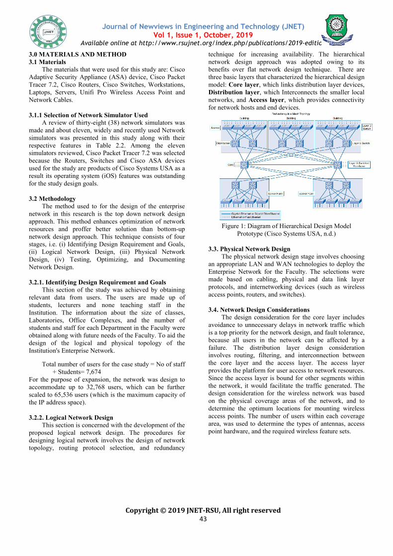
technique for increasing availability. The hierarchical network design approach benefits over flat network designthree basic layers that characterized themodel: Core layer, which linkDistribution layer, which Interconnects the smaller local networks, and Access layer, which provides connectivity for network hosts and end devices.
Figure 1: Diagram of Hierarchical Design Model Prototype (Cisco Systems USA, n.d.)
3.3. Physical Network Design
The physical network design stagean appropriate LAN and WAN technologies Enterprise Network for the Facultymade based on cabling, physical and data link layer protocols, and internetworking devices (such as access points, routers, and switches
3.4. Network Design Considerations
The design consideration for the coreavoidance to unnecessary delays in network traffic which is a top priority for the network design, and fault tolerance, because all users in the network can be affected by a failure. The distribution layer design consideration involves routing, filtering, and interconnection between the core layer and the access layer. The access layer provides the platform for user access to network resources. Since the access layer is bound for other segments within the network, it would facilitate the tradesign consideration for the wireless network was based on the physical coverage areas of the network, and to determine the optimum locations for mounting wireless access points. The number of users within each coverage area, was used to determine the types of antennas, access point hardware, and the required wireless feature sets.
Journal of Newviews in Engineering and Technology (JNET)
Available online at http://www.rsujnet.org/index.php/publications/2019-edition
for increasing availability. The hierarchical was adopted owing to its
benefits over flat network design technique. There are three basic layers that characterized the hierarchical design
, which links distribution layer devices, , which Interconnects the smaller local
, which provides connectivity d end devices.
: Diagram of Hierarchical Design Model
(Cisco Systems USA, n.d.)
3.3. Physical Network Design The physical network design stage involves choosing
an appropriate LAN and WAN technologies to deploy the or the Faculty. The selections were
cabling, physical and data link layer protocols, and internetworking devices (such as wireless
switches).
3.4. Network Design Considerations The design consideration for the core layer includes
avoidance to unnecessary delays in network traffic which is a top priority for the network design, and fault tolerance, because all users in the network can be affected by a failure. The distribution layer design consideration
ing, filtering, and interconnection between the core layer and the access layer. The access layer provides the platform for user access to network resources. Since the access layer is bound for other segments within the network, it would facilitate the traffic generated. The design consideration for the wireless network was based on the physical coverage areas of the network, and to determine the optimum locations for mounting wireless access points. The number of users within each coverage
o determine the types of antennas, access point hardware, and the required wireless feature sets.
Journal of Newviews in Engineering and Technology (JNET)
Available online at http://www.rsujnet.org/index.php/publications/2019
Copyright © 2019 JNET
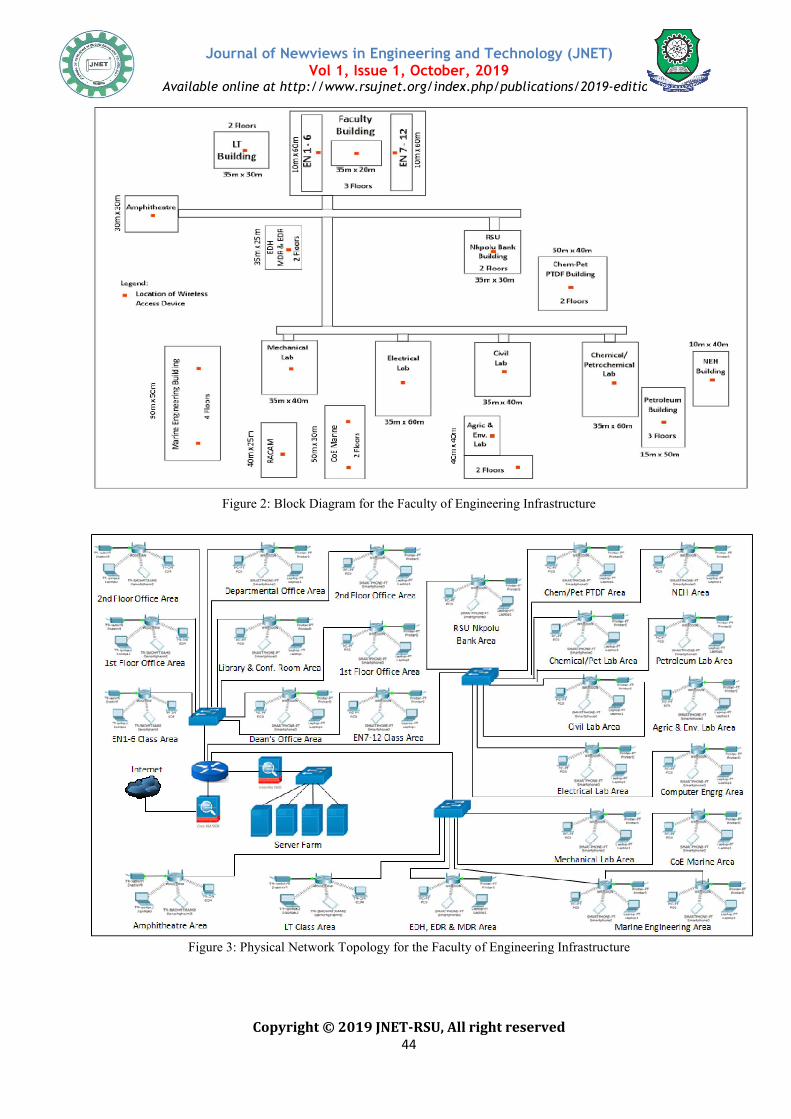
Figure 2: Block Diagram
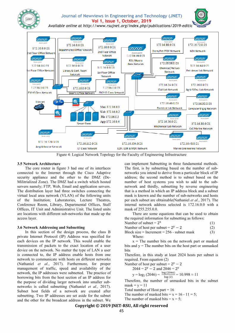
Figure 3: Physical
Journal of Newviews in Engineering and Technology (JNET)Vol 1, Issue 1, October, 2019
Available online at http://www.rsujnet.org/index.php/publications/2019
Copyright © 2019 JNET-RSU, All right reserved 44
Block Diagram for the Faculty of Engineering Infrastructure
: Physical Network Topology for the Faculty of Engineering Infrastructure
Journal of Newviews in Engineering and Technology (JNET)
Available online at http://www.rsujnet.org/index.php/publications/2019-edition
Infrastructure
Infrastructure
Journal of Newviews in Engineering and Technology (JNET)
Available online at http://www.rsujnet.org/index.php/publications/2019
Copyright © 2019 JNET
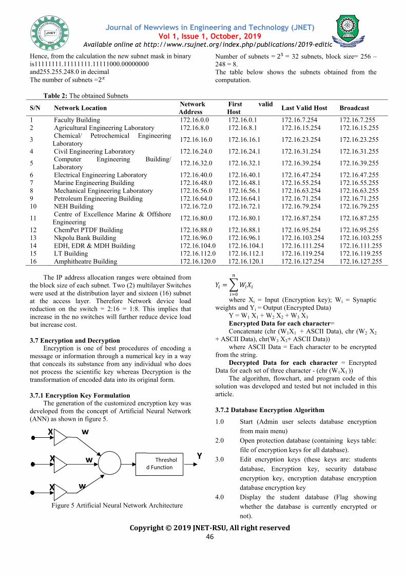
Figure 4: Logical Network
3.5 Network Architecture The core router in figure 3 had one of its
connected to the Internet through the Cisco Adaptive security appliance and the other to thMilitrialized Zone). The DMZ had a switch which hostedservers namely; FTP, Web, Email and application servers. The distribution layer had three switches connecting the virtual local area network (VLAN) of the of the Institution; Laboratories, Lecture Theatres, Conference Room, Library, Departmental Offices, Staff Offices, IT Unit and Administrative Unit. The listed units are locations with different sub-networks that made up the access layer.
3.6 Network Addressing and Subnetting
In this section of the design process, the class B private Internet Protocol (IP) Address was specified for each devices on the IP network. This would enable transmission of packets to the exact location of a device on the network. No matter the type of LAN a user is connected to, the IP address enable hosts network to communicate with hosts on different networks (Nathaniel et al., 2017). Furthermore, for proper management of traffic, speed and availability of the network, the IP addresses were subnetted. borrowing bits from the host section of an IP address the purpose of dividing larger network into smaller subnetworks is called subnetting (Nathaniel Subnet host fields of a network are createdsubnetting. Two IP addresses are set asideand the other for the broadcast address in the subnet.
Journal of Newviews in Engineering and Technology (JNET)Vol 1, Issue 1, October, 2019
Available online at http://www.rsujnet.org/index.php/publications/2019
Copyright © 2019 JNET-RSU, All right reserved 45
Network Topology for the Faculty of Engineering Infrastructure
had one of its interfaces through the Cisco Adaptive
and the other to the DMZ (De-switch which hosted
FTP, Web, Email and application servers. The distribution layer had three switches connecting the virtual local area network (VLAN) of the following units
aboratories, Lecture Theatres, Conference Room, Library, Departmental Offices, Staff
Unit. The listed units networks that made up the
of the design process, the class B
private Internet Protocol (IP) Address was specified for each devices on the IP network. This would enable the
location of a user ype of LAN a user
hosts from one hosts on different networks
. Furthermore, for proper management of traffic, speed and availability of the
were subnetted. The practice of of an IP address for
larger network into smaller sub-(Nathaniel et al., 2017).
are created after set aside for the subnet
in the subnet. We
can implement Subnetting in three The first, is by subnetting based on the number of subnetworks you intend to deriveaddress; the second method number of host systems you wishnetwork and thirdly, subnetting by reverse engineering that is a method in which an IP address block mask is known and the number of subper each subnet are obtainableinternal network address selected mask of 255.255.0.0.
There are some equationthe required information for suNumber of subnet = 2� Number of host per subnet = Block size = Increment = 256
Where: x = The number bits on the network part or masked
bits and y = The number bits on the host part or unmaskedbits Therefore, in this study at least 2024 hosts per subnetrequired. From equation (2) Number of host per subnet =
2044 = 2� − 2 and 2046 =
y = log2 (2046) = ��� (����
��� (�
Therefore, the number of unmasked bits inmask = y = 11 Total number of Host part = 16The number of masked bits = x = 16 The number of masked bits =
Journal of Newviews in Engineering and Technology (JNET)
Available online at http://www.rsujnet.org/index.php/publications/2019-edition
Infrastructure
Subnetting in three fundamental methods. g based on the number of sub-
derive from a particular block of IP the second method is to subnet based on the
systems you wish to add to the sub-subnetting by reverse engineering
an IP address block and a subnet ber of sub-networks and hosts
obtainable(Nathaniel et al., 2017). The address selected is 172.16.0.0 with a
There are some equations that can be used to obtain the required information for subnetting as follows:
(1) Number of host per subnet = 2� − 2 (2)
ement = 256 - subnet mask (3)
he number bits on the network part or masked he number bits on the host part or unmasked
Therefore, in this study at least 2024 hosts per subnet is
Number of host per subnet = 2� − 2 2046 = 2�
����)
�) = 10.998 ≈ 11
he number of unmasked bits in the subnet
Total number of Host part = 16 The number of masked bits = x = 16 - 11 = 5; The number of masked bits = x = 5;
Journal of Newviews in Engineering and Technology (JNET)
Available online at http://www.rsujnet.org/index.php/publications/2019
Copyright © 2019 JNET
Hence, from the calculation the new subnet mask is11111111.11111111.11111000.00000000 and255.255.248.0 in decimal The number of subnets =2�
Table 2: The obtained Subnets
S/N Network Location
1 Faculty Building 2 Agricultural Engineering Laboratory
3 Chemical/ Petrochemical Engineering Laboratory
4 Civil Engineering Laboratory
5 Computer Engineering Building/ Laboratory
6 Electrical Engineering Laboratory7 Marine Engineering Building 8 Mechanical Engineering Laboratory9 Petroleum Engineering Building 10 NEH Building
11 Centre of Excellence Marine & Offshore Engineering
12 ChemPet PTDF Building 13 Nkpolu Bank Building 14 EDH, EDR & MDH Building 15 LT Building 16 Amphitheatre Building
The IP address allocation ranges were obtained from
the block size of each subnet. Two (2) multilayer Switches were used at the distribution layer and sixteen (16) subnet at the access layer. Therefore Network device load reduction on the switch = 2:16 = 1:8. This implies that increase in the no switches will further reduce device load but increase cost.
3.7 Encryption and Decryption
Encryption is one of best procedures of encodingmessage or information through a numerical key in a way that conceals its substance from any individual who does not process the scientific key whereas Decryption is the transformation of encoded data into its original form. 3.7.1 Encryption Key Formulation
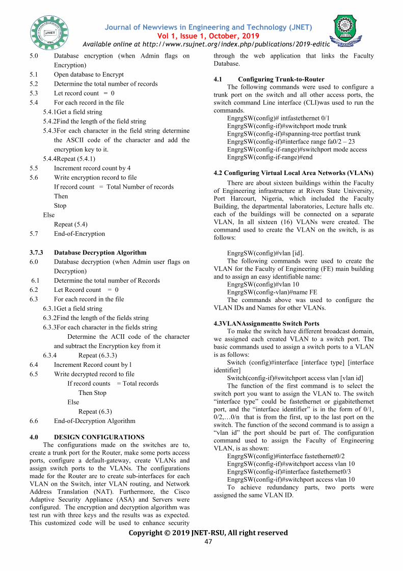
The generation of the customized encryption key was developed from the concept of Artificial Neural Network (ANN) as shown in figure 5.
Figure 5 Artificial Neural Network Architecture
Σ d Function
X
X
X w
w
w
Journal of Newviews in Engineering and Technology (JNET)Vol 1, Issue 1, October, 2019
Available online at http://www.rsujnet.org/index.php/publications/2019
Copyright © 2019 JNET-RSU, All right reserved 46
the new subnet mask in binary s11111111.11111111.11111000.00000000
Number of subnets = 2� = 32 subnets, block size= 256 248 = 8. The table below shows the subnets obtainedcomputation.
Network Address
First valid Host
Last Valid Host
172.16.0.0 172.16.0.1 172.16.7.254Agricultural Engineering Laboratory 172.16.8.0 172.16.8.1 172.16.15.254Chemical/ Petrochemical Engineering
172.16.16.0 172.16.16.1 172.16.23.254
172.16.24.0 172.16.24.1 172.16.31.254Computer Engineering Building/
172.16.32.0 172.16.32.1 172.16.39.254
Electrical Engineering Laboratory 172.16.40.0 172.16.40.1 172.16.47.254172.16.48.0 172.16.48.1 172.16.55.254
Mechanical Engineering Laboratory 172.16.56.0 172.16.56.1 172.16.63.254 172.16.64.0 172.16.64.1 172.16.71.254
172.16.72.0 172.16.72.1 172.16.79.254Centre of Excellence Marine & Offshore
172.16.80.0 172.16.80.1 172.16.87.254
172.16.88.0 172.16.88.1 172.16.95.254172.16.96.0 172.16.96.1 172.16.103.254172.16.104.0 172.16.104.1 172.16.111.254172.16.112.0 172.16.112.1 172.16.119.254172.16.120.0 172.16.120.1 172.16.127.254
The IP address allocation ranges were obtained from Two (2) multilayer Switches
were used at the distribution layer and sixteen (16) subnet ess layer. Therefore Network device load
. This implies that increase in the no switches will further reduce device load
Encryption is one of best procedures of encoding a message or information through a numerical key in a way that conceals its substance from any individual who does not process the scientific key whereas Decryption is the transformation of encoded data into its original form.
The generation of the customized encryption key was developed from the concept of Artificial Neural Network
Figure 5 Artificial Neural Network Architecture
�� = � ����
�
���
where Xi = Input (Encryption key); Wweights and Yi = Output (Encrypted Data)
Y = W1 X1 + W2 X2 + WEncrypted Data for each characterConcatenate (chr (W1X
+ ASCII Data), chr(W3 X3+ ASCII Data))where ASCII Data = Each character to be encrypted
from the string. Decrypted Data for each character
Data for each set of three character The algorithm, flowchart
solution was developed and tested but not included in this article.
3.7.2 Database Encryption Algorithm
1.0 Start (Admin user selects database encryption
from main menu)
2.0 Open protection database (containing keys table:
file of encryption keys for all database).
3.0 Edit encryption keys (these keys are: st
database, Encryption key, security database
encryption key, encryption database encryption
database encryption key
4.0 Display the student database (Flag showing
whether the database is currently encrypted or
not).
Threshold Function
Y
Journal of Newviews in Engineering and Technology (JNET)
Available online at http://www.rsujnet.org/index.php/publications/2019-edition
= 32 subnets, block size= 256 –
the subnets obtained from the
Last Valid Host Broadcast
172.16.7.254 172.16.7.255 172.16.15.254 172.16.15.255
172.16.23.254 172.16.23.255
172.16.31.254 172.16.31.255
172.16.39.254 172.16.39.255
172.16.47.254 172.16.47.255 172.16.55.254 172.16.55.255 172.16.63.254 172.16.63.255 172.16.71.254 172.16.71.255 172.16.79.254 172.16.79.255
172.16.87.254 172.16.87.255
172.16.95.254 172.16.95.255 172.16.103.254 172.16.103.255 172.16.111.254 172.16.111.255 172.16.119.254 172.16.119.255 172.16.127.254 172.16.127.255
= Input (Encryption key); Wi = Synaptic = Output (Encrypted Data)
+ W3 X3 Encrypted Data for each character=
X1 + ASCII Data), chr (W2 X2 + ASCII Data))
= Each character to be encrypted
Decrypted Data for each character = Encrypted Data for each set of three character - (chr (W1X1 ))
lgorithm, flowchart, and program code of this and tested but not included in this
3.7.2 Database Encryption Algorithm
Start (Admin user selects database encryption
Open protection database (containing keys table:
file of encryption keys for all database).
Edit encryption keys (these keys are: students
database, Encryption key, security database
encryption key, encryption database encryption
database encryption key
Display the student database (Flag showing
whether the database is currently encrypted or
Journal of Newviews in Engineering and Technology (JNET)
Available online at http://www.rsujnet.org/index.php/publications/2019
Copyright © 2019 JNET
5.0 Database encryption (when Admin f
Encryption)
5.1 Open database to Encrypt
5.2 Determine the total number of records
5.3 Let record count = 0
5.4 For each record in the file
5.4.1Get a field string
5.4.2Find the length of the field string
5.4.3For each character in the field string determine
the ASCII code of the character and add the
encryption key to it.
5.4.4Repeat (5.4.1)
5.5 Increment record count by 4
5.6 Write encryption record to file
If record count = Total Number of records
Then
Stop
Else
Repeat (5.4)
5.7 End-of-Encryption
3.7.3 Database Decryption Algorithm
6.0 Database decryption (when Admin user flags on
Decryption)
6.1 Determine the total number of Records
6.2 Let Record count = 0
6.3 For each record in the file
6.3.1Get a field string
6.3.2Find the length of the fields string
6.3.3For each character in the fields string
Determine the ACII code of the character
and subtract the Encryption key from it
6.3.4 Repeat (6.3.3)
6.4 Increment Record count by l
6.5 Write decrypted record to file
If record counts = Total records
Then Stop
Else
Repeat (6.3)
6.6 End-of-Decryption Algorithm
4.0 DESIGN CONFIGURATIONS The configurations made on the switches
create a trunk port for the Router, make someports, configure a default-gateway, create VLANs and assign switch ports to the VLANs. The configurations made for the Router are to create sub-interfaces for each VLAN on the Switch, inter VLAN routing,Address Translation (NAT). Furthermore, the Cisco Adaptive Security Appliance (ASA) and Servers were configured. The encryption and decryption algorithm was test run with three keys and the results was as expected. This customized code will be used to enhance security
Journal of Newviews in Engineering and Technology (JNET)Vol 1, Issue 1, October, 2019
Available online at http://www.rsujnet.org/index.php/publications/2019
Copyright © 2019 JNET-RSU, All right reserved 47
Database encryption (when Admin flags on
Determine the total number of records
5.4.2Find the length of the field string
eld string determine
the ASCII code of the character and add the
If record count = Total Number of records
Database Decryption Algorithm
Database decryption (when Admin user flags on
Determine the total number of Records
6.3.2Find the length of the fields string
6.3.3For each character in the fields string
Determine the ACII code of the character
and subtract the Encryption key from it
If record counts = Total records
ade on the switches are to,
some ports access gateway, create VLANs and
The configurations interfaces for each
inter VLAN routing, and Network Furthermore, the Cisco
tive Security Appliance (ASA) and Servers were The encryption and decryption algorithm was
test run with three keys and the results was as expected. customized code will be used to enhance security
through the web application that links Database.
4.1 Configuring Trunk
The following commands were used ttrunk port on the switch and all other access portsswitch command Line interface (CLI)commands.
EngrgSW(config)# intfastethernet EngrgSW(config-if)#switchport mode trunkEngrgSW(config-if)#spanningEngrgSW(config-if)#interface range fa0/2 EngrgSW(config-if-range)#switchport mode accessEngrgSW(config-if-range)#end
4.2 Configuring Virtual Local Area Netw
There are about sixteenof Engineering infrastructure at Rivers State University, Port Harcourt, Nigeria, which included the Faculty Building, the departmental laboratories, Lecture halls etc. each of the buildings will be connected on a separate VLAN, In all sixteen (16) VLANs were created. The command used to create the VLAN on the switch, is as follows:
EngrgSW(config)#vlan [id].The following commands were used to
VLAN for the Faculty of Engineering and to assign an easy identifiable name
EngrgSW(config)#vlan 10EngrgSW(config-vlan)#name FEThe commands above
VLAN IDs and Names for other
4.3VLANAssignmentto Switch Ports To make the switch have dif
we assigned each created VLANbasic commands used to assign is as follows:
Switch (config)#interface [interface type] [interface identifier]
Switch(config-if)#switchport access vlan [vThe function of the first command is to select the
switch port you want to assign “interface type” could be fastethernetport, and the “interface identifier” 0/2,…0/n that is from the first, up to the switch. The function of the second command is to assign a “vlan id” the port should be part ofcommand used to assign the Faculty of Engineering VLAN, is as shown:
EngrgSW(config)#interface fastethernet0EngrgSW(config-if)#switchport access vlan 10EngrgSW(config-if)#interface fastethernet0/3EngrgSW(config-if)#switchport access vlan 10To achieve redundancy
assigned the same VLAN ID
Journal of Newviews in Engineering and Technology (JNET)
Available online at http://www.rsujnet.org/index.php/publications/2019-edition
through the web application that links the Faculty
Trunk-to-Router he following commands were used to configure a
and all other access ports, the command Line interface (CLI)was used to run the
(config)# intfastethernet 0/1 if)#switchport mode trunk if)#spanning-tree portfast trunk if)#interface range fa0/2 – 23
range)#switchport mode access range)#end
Virtual Local Area Networks (VLANs)
sixteen buildings within the Faculty infrastructure at Rivers State University,
, which included the Faculty Building, the departmental laboratories, Lecture halls etc.
s will be connected on a separate VLAN, In all sixteen (16) VLANs were created. The command used to create the VLAN on the switch, is as
(config)#vlan [id]. mmands were used to create the
Faculty of Engineering (FE) main building to assign an easy identifiable name:
(config)#vlan 10 vlan)#name FE
commands above was used to configure the for other VLANs.
Switch Ports o make the switch have different broadcast domain,
VLAN to a switch port. The o assign a switch ports to a VLAN
(config)#interface [interface type] [interface
if)#switchport access vlan [vlan id] first command is to select the
you want to assign the VLAN to. The switch fastethernet or gigabitethernet
port, and the “interface identifier” is in the form of 0/1, first, up to the last port on the
The function of the second command is to assign a should be part of. The configuration
o assign the Faculty of Engineering
(config)#interface fastethernet0/2 if)#switchport access vlan 10 if)#interface fastethernet0/3 if)#switchport access vlan 10
o achieve redundancy parts, two ports were ID.
Journal of Newviews in Engineering and Technology (JNET)
Available online at http://www.rsujnet.org/index.php/publications/2019
Copyright © 2019 JNET
4.4 Default-Gateway Configuration The basic command used for configuring
gateway for each VLANs is shown below. The default gateway is configured to enables packets destined for outside network.
Switch(config)#ip default-gateway [ip address].In the command above the “ip address” is for the
interface linking the VLAN to the Router. commands configured for the gateways is as follows:The Faculty of Engineering: VLAN 10 FE(config)#ip default-gateway 172.16.0.1 The Agric and Environmental Engineering Lab: VLAN 20AGRICSW(config)#ip default-gateway 172.16.8.1The Chemical Petrochemical Engineering Lab:CHEMSW(config)#ip default-gateway 172.16.16.1The Civil Engineering Lab: VLAN 40 CIVSW(config)#ip default-gateway 172.16.24.1The Computer Engineering Building/Lab: VLAN 50CENSW(config)#ip default-gateway 172.16.32.1The Electrical Engineering Lab: VLAN 60 EEESW(config)#ip default-gateway 172.16.40.1The Marine Engineering Building/Lab: VLAN 70MARSW(config)#ip default-gateway 172.16.48.1The Mechanical Engineering Lab: VLAN 8MECSW(config)#ip default-gateway 172.16.56.1The Petroleum Engineering Building: VLAN 90PETSW(config)#ip default-gateway 172.16.64.1The New Engineering Hall Building: VLAN 100NEHSW(config)#ip default-gateway 172.16.72.1The CoE Marine and Offshore Engineering: VLAN 110COESW(config)#ip default-gateway 172.16.80.1The PTDF Building of Chemical/Petrochemical Engineering: VLAN 120 CPTDFSW(config)#ip default-gateway 172.16.88.1The RSU Nkpolu Bank Building: VLAN 130RSUNBSW(config)#ip default-gateway 172.16.The Faculty Engineering Drawing Hall Building: VLAN 140 EDHSW(config)#ip default-gateway 172.16.104.1The Lecture Theatre(LT1-3) Building: VLAN 150LTSW(config)#ip default-gateway 172.16.112.1The Amphitheatre: VLAN 160 AMPHSW(config)#ip default-gateway 172.16.120.1 4.5 Configuring Network Address Translation (NAT)
The configuration of NAT were made on the router for the inside and outside interfaceinterface indicates traffic coming from an external network while the Inside interface indicates traffic coming from within the Institution’s network the commands Core_Router(config)#interface fa 0/0 Core_Router(config-if)#ip add 192.168.8.2255.255.255.252 Core_Router(config-if)#ipnat outside Core_Router(config-if)#interface gigabitethernetCore_Router(config-if)#ip add 172.16.0.5 255.255.0Core_Router(config-if)#ipnat inside
Journal of Newviews in Engineering and Technology (JNET)Vol 1, Issue 1, October, 2019
Available online at http://www.rsujnet.org/index.php/publications/2019
Copyright © 2019 JNET-RSU, All right reserved 48
and used for configuring the default gateway for each VLANs is shown below. The default gateway is configured to enables packets destined for
gateway [ip address]. “ip address” is for the
the VLAN to the Router. Therefore, the commands configured for the gateways is as follows:
The Agric and Environmental Engineering Lab: VLAN 20
gateway 172.16.8.1 The Chemical Petrochemical Engineering Lab: VLAN 30
gateway 172.16.16.1
gateway 172.16.24.1 The Computer Engineering Building/Lab: VLAN 50
gateway 172.16.32.1
gateway 172.16.40.1 The Marine Engineering Building/Lab: VLAN 70
gateway 172.16.48.1 The Mechanical Engineering Lab: VLAN 80
gateway 172.16.56.1 The Petroleum Engineering Building: VLAN 90
gateway 172.16.64.1 The New Engineering Hall Building: VLAN 100
gateway 172.16.72.1 ineering: VLAN 110
gateway 172.16.80.1 of Chemical/Petrochemical
gateway 172.16.88.1 The RSU Nkpolu Bank Building: VLAN 130
gateway 172.16.96.1 The Faculty Engineering Drawing Hall Building: VLAN
gateway 172.16.104.1 LAN 150
gateway 172.16.112.1
ay 172.16.120.1
Configuring Network Address Translation (NAT) were made on the core
interface. The outside interface indicates traffic coming from an external network
ndicates traffic coming from commands used are:
if)#ip add 192.168.8.2
tethernet 0/1 255.255.0.0
4.6 Configuring the Sub-Interfaces for Each VLAN Sub-interfaces were configured on the router interface linking the trunk port on the switch becausemore costly to purchase a interfaces. The sub-interfaces will enable packets of different VLANs to reach the routerused to create the sub-interfacesCore_router(config)#interface [interfaidentifier break] The parameter “interface type” is either a fastEthernet port or a gigabitparameter “interface identifier break” the sub-interfaces for examplesub-interface. The router subNAT and inter-VLAN routingcommands below. CoreRouter#configure terminalCoreRouter(config)# interface gig0/1CoreRouter(config-if)#no ip addressCoreRouter(config-if)#duplex autoCoreRouter(config-if)#speed autoCoreRouter(config-if)#interface gig0/1.1CoreRouter(config-subif)#description VLAN10_interfaceCoreRouter(config-subif)#encapsulation dot1q 10CoreRouter(config-subif)#ip address 172.16.0.1 255.255.248.0 CoreRouter(config-subif)#ipnat insideCoreRouter(config-subif)#ip helperCoreRouter(config-subif)#endTheID for the different VLANs and the IP address to the VLAN were configured using the same command above. 4.7Configuring the Cisco Adaptive (ASA) The following commands were used to configureCisco ASA, the ASA command Line interface (CLI)was used to run the commands: engrgasa(config)# interface GigabitEthernet0/0engrgasa(config-if)# speed 100engrgasa(config-if)# duplex fullengrgasa(config-if)# no nameifengrgasa(config-if)# no securityengrgasa(config-if)# no ip addressengrgasa(config-if)# interface GigabitEengrgasa(config-subif)# description OUTSIDE1engrgasa(config-subif)# vlan 5engrgasa(config-subif)# nameif OUengrgasa(config-subif)# securityengrgasa(config-subif)# ip address 192.168.8.1 255.255.255.0 engrgasa(config-if)# interface GigabitEthernet0/1engrgasa(config-subif)# speed 100engrgasa(config-subif)# duplex fullengrgasa(config-subif)# no namengrgasa(config-subif)# no securityengrgasa(config-subif)# no ip addressengrgasa(config-if)# interface GigabitEthernet0/1.10engrgasa(config-subif)# description INSIDE1engrgasa(config-subif)# vlan 10engrgasa(config-subif)# nameif INSIDE1engrgasa(config-subif)# security
Journal of Newviews in Engineering and Technology (JNET)
Available online at http://www.rsujnet.org/index.php/publications/2019-edition
Interfaces for Each VLAN interfaces were configured on the router
interface linking the trunk port on the switch because it is router with large number of
interfaces will enable packets of different VLANs to reach the router. The basic command
interfaces is as shown below: _router(config)#interface [interface type] [interface
“interface type” is either a gigabitEthernet port and the
“interface identifier break” begins the setup of interfaces for example 0/1.1 to configure the first
router sub-interfaces, DHCP relay, VLAN routing was configured using the
outer#configure terminal outer(config)# interface gig0/1
if)#no ip address if)#duplex auto if)#speed auto if)#interface gig0/1.1 subif)#description VLAN10_interface subif)#encapsulation dot1q 10 subif)#ip address 172.16.0.1
#ipnat inside subif)#ip helper-address 172.16.4.3 subif)#end
ID for the different VLANs and the IP address to the VLAN were configured using the same command above.
the Cisco Adaptive Security Appliance
The following commands were used to configure the command Line interface (CLI)was
engrgasa(config)# interface GigabitEthernet0/0 if)# speed 100 if)# duplex full if)# no nameif if)# no security-level if)# no ip address if)# interface GigabitEthernet0/0.5 subif)# description OUTSIDE1 subif)# vlan 5 subif)# nameif OUT1 subif)# security-level 0 subif)# ip address 192.168.8.1
if)# interface GigabitEthernet0/1 subif)# speed 100 subif)# duplex full subif)# no nameif subif)# no security-level subif)# no ip address if)# interface GigabitEthernet0/1.10 subif)# description INSIDE1 subif)# vlan 10 subif)# nameif INSIDE1 subif)# security-level 90
Journal of Newviews in Engineering and Technology (JNET)
Available online at http://www.rsujnet.org/index.php/publications/2019
Copyright © 2019 JNET
engrgasa(config-subif)# ip address 172.16.0.1 255.255.248.0 The commands above was repeated to configure VLANs.
4.8 Configuration of the Wireless Access Point
The wireless access point was configured usgraphical user interface (GUI) in Packet TracerGUI the config tab was selected to access the configuration options on the WAP. bandwidth of the Ethernet connection of the WAP, con port 0 under the interface section and duplex (full duplex or half duplex). To setup the SSID of the WAP, click on port 1 under the interface section,
VLAN 10 Configuration Parameters: Poolname: VLAN10 Default gateway: 172.16.0.1 DNS server: 172.16.4.3 Start IP address: 172.16.0.16 Subnet mask: 255.255. 248.0 Total users: 2046
VLAN 40 Configuration Parameters: Poolname: VLAN40 Default gateway: 172.16.24.1 DNS server: 172.16.4.3 Start IP address: 172.16.24.5 Subnet mask: 255.255. 248.0 Total users: 2046 VLAN 70 Configuration Parameters: Poolname: VLAN70 Default gateway:172.16.48.1 DNS server: 172.16.4.3 Start IP address: 172.16.48.5 Subnet mask: 255.255. 248.0 Total users: 2046 VLAN 100 Configuration Parameters: Poolname: VLAN100 Default gateway: 172.16.72.1 DNS server: 172.16.4.3 Start IP address: 172.16.72.5 Subnet mask: 255.255. 248.0 Total users: 2046 VLAN 130 Configuration Parameters: Poolname: VLAN130 Default gateway: 172.16.96.1 DNS server: 172.16.4.3 Start IP address: 172.16.96.5 Subnet mask: 255.255. 248.0 Total users: 2046
The add button was used to include parameter of the address pools for each VLANs on the DHCP server. Not all the IP addresses are DHCP address pools. The reason is to reserve them for
Journal of Newviews in Engineering and Technology (JNET)Vol 1, Issue 1, October, 2019
Available online at http://www.rsujnet.org/index.php/publications/2019
Copyright © 2019 JNET-RSU, All right reserved 49
subif)# ip address 172.16.0.1
configure the other
Wireless Access Point (WAP) configured using the
in Packet Tracer. From the GUI the config tab was selected to access the
To select the of the Ethernet connection of the WAP, click
on port 0 under the interface section and then set the To setup the SSID of
lick on port 1 under the interface section, select
authentication type e.g. WPA2WEP, WPA-PSK, WPA2-PSK) and for the chosen authentication
4.9 Setting up of Dynamic Host Configuration Protocol (DHCP) Server
The graphical user interface of the first server was used to configure the DHCP server service from the services tab, DHCP service for onward configuration of the DHCP address pools for each VLANs on the institution'snetwork. The command used to configure thepools on the server is as follows:
VLAN 20 Configuration Parameters: Poolname: VLAN20 Default gateway: 172.16.8.1 DNS server: 172.16.4.3 Start IP address: 172.16.8.5 Subnet mask: 255.255.248.0 Totalusers: 2046
VLAN 30 Configuration Parameters:Poolname: VLAN30Default gateway: 172.16.16.1DNS server: 172.16.4.3Start IP address: 172.16.16.5Subnet mask: 255.255. 248.0Total users: 2046
VLAN 50 Configuration Parameters: Poolname: VLAN50 Default gateway: 172.16.32.1 DNS server: 172.16.4.3 Start IP address: 172.16.32.5 Subnet mask: 255.255. 248.0 Total users: 2046
VLAN 60 Configuration Parameters:Poolname: VLAN60Default gateway: 172.16.40.1DNS server: 172.16.4.3Start IP address:172.16.40.5Subnet mask: 255.255. 248.0Total of users: 2046
VLAN 80 Configuration Parameters: Poolname: VLAN80 Default gateway: 172.16.56.1 DNS server: 172.16.4.3 Start IP address: 172.16.56.5 Subnet mask: 255.255. 248.0 Total users: 2046
VLAN 90 ConfigurationParameters:Poolname: VLAN90Default gateway: 172.16.64.1DNS server: 172.16.4.3Start IP address: 172.16.64.5Subnet mask: 255.255. 248.0Total users: 2046
VLAN 110 Configuration Parameters: Poolname: VLAN110 Default gateway: 172.16.80.1 DNS server: 172.16.4.3 Start IP address: 172.16.80.5 Subnet mask: 255.255. 248.0 Total users: 2046
VLAN 120 Configuration Parameters:Poolname: VLAN120Default gateway: 172.16.88.1DNS server: 172.16.4.3Start IP address: 172.16.88.5Subnet mask: 255.255. 248.0Total users: 2046
VLAN 140 Configuration Parameters: Poolname: VLAN140 Default gateway: 172.16.104.1 DNS server: 172.16.4.3 Start IP address: 172.16.104.5 Subnet mask: 255.255. 248.0 Total users: 2046
VLAN 150 Configuration Parameters:Poolname: VLAN150Default gateway: 172.16.112DNS server: 17Start IP address: 172.16.Subnet mask: 255.255. 248.0Total users: 2046
The add button was used to include the inputted
parameter of the address pools for each VLANs on the IP addresses are used for the
to reserve them for
some network equipment assignment of static IP address and alsoof the network. In this research for the administrative centre
Journal of Newviews in Engineering and Technology (JNET)
Available online at http://www.rsujnet.org/index.php/publications/2019-edition
e.g. WPA2-PSK among others (none, PSK) and input the passphrase
ication for network connectivity.
Dynamic Host Configuration Protocol
graphical user interface of the first server was DHCP server by selecting the DHCP
service from the services tab, and thereafter turn on the for onward configuration of the DHCP
address pools for each VLANs on the institution's and used to configure the address as follows:
Configuration Parameters: Poolname: VLAN30 Default gateway: 172.16.16.1 DNS server: 172.16.4.3 Start IP address: 172.16.16.5 Subnet mask: 255.255. 248.0 Total users: 2046
VLAN 60 Configuration Parameters: Poolname: VLAN60 Default gateway: 172.16.40.1 DNS server: 172.16.4.3 Start IP address:172.16.40.5 Subnet mask: 255.255. 248.0 Total of users: 2046
Configuration Parameters: Poolname: VLAN90 Default gateway: 172.16.64.1 DNS server: 172.16.4.3 Start IP address: 172.16.64.5 Subnet mask: 255.255. 248.0
tal users: 2046 Configuration
Parameters: Poolname: VLAN120 Default gateway: 172.16.88.1 DNS server: 172.16.4.3 Start IP address: 172.16.88.5
ubnet mask: 255.255. 248.0 Total users: 2046 VLAN 150 Configuration Parameters: Poolname: VLAN150 Default gateway: 172.16.112.1 DNS server: 172.16.4.3 Start IP address: 172.16.112.5 Subnet mask: 255.255. 248.0 Total users: 2046
some network equipment that may require manual address and also for the expansion
In this research VLAN 10 is the network centre of the institution. In this
Journal of Newviews in Engineering and Technology (JNET)
Available online at http://www.rsujnet.org/index.php/publications/2019
Copyright © 2019 JNET
VLAN more IP address were reserved to enable the network administrator manually assign static IP addresses to network equipments at the centre.
4.10 Setup of Domain Name Server (DNS)
The graphical user interface (GUI) of the fourth server was used to configure the DNS serverachieved by clicking the services tab, and choosing the DNS service. Thereafter turning on the DNS service and inputting the fully qualified domain Name (FQDN) name textbox e.g. engfaculty.com and the IP address inaddress textbox. The inputted record is added to the server by clicking the add button.
4.11 Hyper Text Transfer Protocol (HTTP) Server Setup
The graphical user interface (GUI) of the third server was used to configure the HTTP server. This was acby clicking the services tab, and choosing the service. Afterward the window displays the configuration options for the web server. To upload the website of the institution, select the import option of interface to upload web pages that had been
4.12 Email Server Setup
The graphical user interface (GUI) of the fourth server was used to configure the email server. This was achieved by clicking the services tab, and choosing the email service. Afterward the window displaconfiguration options for the email server. The options are;
(i) Choose the simple mail transfer protocol (SMTP) service to turn it on.
(ii) Choose the POP3 service to turn it on.(iii) Input the domain name for your mail server i.e.
engfaculty.com. And then clickconfigure the domain.
(iv) In the user creation interface, input the username and password for every users on the email server. and then click on “+” to add the user to the mail server.
(v) The changing of a user’s password is accomplished by clicking onpassword button. A dialog box is displayed with the option to enter a new password thereafter select on ok to change the password.
we have proposed and talked about another way to deal with structuring secure undertaking systems for an Institution. The methodology not just stresses the significance of utilizing hierarchical objectives and in structuring a safe system yet in addition gives worked in components to catch security needs and use them consistently all through the means of dissecting aplanning secure system design.
4.13 Authentication, Authorization, and Accounting (AAA) Server Settings
In the simulation environment, click on the first server icon and when its dialogue box is opened, look for
Journal of Newviews in Engineering and Technology (JNET)Vol 1, Issue 1, October, 2019
Available online at http://www.rsujnet.org/index.php/publications/2019
Copyright © 2019 JNET-RSU, All right reserved 50
VLAN more IP address were reserved to enable the network administrator manually assign static IP addresses
Domain Name Server (DNS) graphical user interface (GUI) of the fourth
the DNS server. This was and choosing the
on the DNS service and the fully qualified domain Name (FQDN) in the
IP address in the textbox. The inputted record is added to the DNS
Hyper Text Transfer Protocol (HTTP) Server
graphical user interface (GUI) of the third server This was achieved
by clicking the services tab, and choosing the HTTP the configuration
To upload the website of the the web server
been developed.
The graphical user interface (GUI) of the fourth server was used to configure the email server. This was achieved by clicking the services tab, and choosing the email service. Afterward the window displays the configuration options for the email server. The options
Choose the simple mail transfer protocol (SMTP)
Choose the POP3 service to turn it on. Input the domain name for your mail server i.e. engfaculty.com. And then click on set to
In the user creation interface, input the username and password for every users on the email server. and then click on “+” to add the user to the mail
The changing of a user’s password is accomplished by clicking on the change password button. A dialog box is displayed with the option to enter a new password thereafter select on ok to change the password.
we have proposed and talked about another way to deal with structuring secure undertaking systems for an
ion. The methodology not just stresses the significance of utilizing hierarchical objectives and in structuring a safe system yet in addition gives worked in components to catch security needs and use them consistently all through the means of dissecting and
4.13 Authentication, Authorization, and Accounting
the simulation environment, click on the first server icon and when its dialogue box is opened, look for
the service tap and select AAA option. Tthe service of the AAA and thenthe router that is connected to the AAA server such as hostname, IP address, server keyoptions either Radius or TACACS server. proceed to the user setup, bydetails to enable them have access to the devices on the network that is username and
4.14 Securing the Network
The network security setup involves
4.15 Setting up Passwords on All Switches and the Router
To setup password on either the switch or router, it should be connected to the console port of a PC and afterwards open hyper terminal window to display the command line interface to configure it with the following command:
CoreRouter>enable CoreRouter#configure terminalCoreRouter(config)#enable secret group16CoreRouter(config)#service passwordCoreRouter(config)#endCoreRouter#write memory In the command above, the router password
to group 16 and the “service passwordenabled and the code saved in the memory. same command was used to configure the switches
4.16 Setting up Console Port and Telnet Connection Passwords
The following command were used to configure the router or the switches:
CoreRouter(config)#line vty 0 4CoreRouter(config-line)#password group16CoreRouter(config-line)#loginCoreRouter(config-line)#endCoreRouter(config)#line console 0CoreRouter(config-line)#password group16CoreRouter(config-line)#loginWhere group16 is the passw
telnet (vty) and console port connections.
4.17 Setting up Secure Shell (SSH)The following command were used to setup SSH which is a secured type of telnet. In SSH passwords are encrypted before transmission across the networkSetting up secure shell involves the following commands:Router(config)#hostname CoreRouterCoreRouter(config)#ip domainCoreRouter(config)#crypto key generate rsa generalmodulus 1024 CoreRouter(config)#ip ssh authenticationCoreRouter(config)#line vty 0 1180CoreRouter(config)#transport input ssh telnetThe modulus of 1024 indicates the strength of the rsa key to be generated.
Journal of Newviews in Engineering and Technology (JNET)
Available online at http://www.rsujnet.org/index.php/publications/2019-edition
the service tap and select AAA option. Thereafter turn on the service of the AAA and then, enter the parameters of the router that is connected to the AAA server such as
, server key, and then the AAA server either Radius or TACACS server. Furthermore,
by entering all the users account details to enable them have access to the devices on the
and password.
The network security setup involves:
4.15 Setting up Passwords on All Switches and the
To setup password on either the switch or router, it should be connected to the console port of a PC and afterwards open hyper terminal window to display the command line interface to configure it with the following
ter#configure terminal CoreRouter(config)#enable secret group16 CoreRouter(config)#service password-encryption CoreRouter(config)#end CoreRouter#write memory
In the command above, the router password was fixed “service password-encryption” was
enabled and the code saved in the memory. Similarly, the used to configure the switches.
4.16 Setting up Console Port and Telnet Connection
The following command were used to configure the
uter(config)#line vty 0 4 line)#password group16 line)#login line)#end
CoreRouter(config)#line console 0 line)#password group16 line)#login
Where group16 is the password set up for both the telnet (vty) and console port connections.
4.17 Setting up Secure Shell (SSH) The following command were used to setup SSH which is a secured type of telnet. In SSH passwords are encrypted before transmission across the network.
tting up secure shell involves the following commands: Router(config)#hostname CoreRouter CoreRouter(config)#ip domain-name engcomplex.com CoreRouter(config)#crypto key generate rsa general-key
CoreRouter(config)#ip ssh authentication-retries 3 CoreRouter(config)#line vty 0 1180 CoreRouter(config)#transport input ssh telnet The modulus of 1024 indicates the strength of the rsa key
Journal of Newviews in Engineering and Technology (JNET)
Available online at http://www.rsujnet.org/index.php/publications/2019
Copyright © 2019 JNET
4.18 Setting up an AAA Model on the RouterThe following command were used to configure the AAA server for the purpose of authentication on the routerCoreRouter(config)#aaa new-model CoreRouter(config)#tacacs-server host 172.16.4.1 key secret CoreRouter(config)#aaa authentication login ACCESS group tacacs+ CoreRouter(config)#line console 0 CoreRouter(config-line)#login authentication ACCESSCoreRouter(config-line)#end CoreRouter#write memory 4.19 The Prototype Implementation of the Secured Enterprise Network Using Cisco Packet Tracer
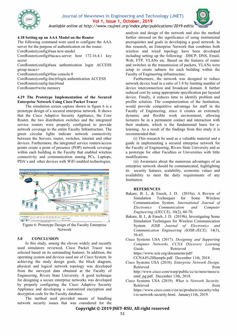
The simulation screen capture shown in figure 6 is a prototype design of a secured enterprise network. It shows that the Cisco Adaptive Security Appliance, the Core Router, the two distribution switches and the integrated service routers were properly configured to provide network coverage to the entire Faculty Infrastrugreen circular lights indicate network connectivity between the Servers, router, switches, internet and other devices. Furthermore, the integrated service routers/access points create a point of presence (POP) network coverage within each building in the Faculty that enabled wireless connectivity and communication among PCs, Laptops, PDA’s and other devices with WiFi enabled technologies
Figure 6: Prototype Design of the Faculty Enterprise Network
5.0 CONCLUSION
In this study, among the eleven widely and recently used simulators reviewed, Cisco Packet Tracer was selected based on its outstanding features. Ioperating system and devices used are of Cisco System. In achieving the study design goals, the block diagram, physical and logical network topology was developed from the surveyed data obtained at the Faculty of Engineering, Rivers State University. A for designing a secure enterprise networks was developed by properly configuring the Cisco Adaptive Security Appliance and developing a customized decryption code for the Faculty database.
The method used provided meansnetwork security issues that was considered for the
Journal of Newviews in Engineering and Technology (JNET)Vol 1, Issue 1, October, 2019
Available online at http://www.rsujnet.org/index.php/publications/2019
Copyright © 2019 JNET-RSU, All right reserved 51
up an AAA Model on the Router The following command were used to configure the AAA erver for the purpose of authentication on the router.
server host 172.16.4.1 key
CoreRouter(config)#aaa authentication login ACCESS
line)#login authentication ACCESS
4.19 The Prototype Implementation of the Secured Using Cisco Packet Tracer
The simulation screen capture shown in figure 6 is a ign of a secured enterprise network. It shows
that the Cisco Adaptive Security Appliance, the Core Router, the two distribution switches and the integrated service routers were properly configured to provide network coverage to the entire Faculty Infrastructure. The green circular lights indicate network connectivity between the Servers, router, switches, internet and other devices. Furthermore, the integrated service routers/access points create a point of presence (POP) network coverage
ng in the Faculty that enabled wireless connectivity and communication among PCs, Laptops, PDA’s and other devices with WiFi enabled technologies.
Figure 6: Prototype Design of the Faculty Enterprise
ven widely and recently used simulators reviewed, Cisco Packet Tracer was
features. In addition, the Cisco System. In
achieving the study design goals, the block diagram, nd logical network topology was developed
from the surveyed data obtained at the Faculty of Engineering, Rivers State University. A good technique for designing a secure enterprise networks was developed by properly configuring the Cisco Adaptive Security
encryption and
provided means of handling network security issues that was considered for the
analysis and design of the network and also the method further stressed on the significance of using institutional prerequisites and goals in developing a good network. In this research, an Enterprise Network that combines both wireless and wired topology have been developed including setting up the following: DHCP, DNS, Web, FTP, VLANs etc. Based on the features of router and switches in the transmission of packets, VLANs were setup to create subnets for each building within the Faculty of Engineering infrastructure.
Furthermore, the network was designed to reducenetwork device load in a ratio of 1:8 by limiting number of device interconnection and broadcast domain. It further reduced cost by using appropriate specification per layered device. Finally, it reduces time to identify problem and proffer solution. The computerization ofwould provide competitive advantage for staff in the Faculty of Engineering, since it creates an extremely dynamic and flexible work environment, allowing lecturers be in a permanent contact and interaction with their students, which is the fundamental basis for elearning. As a result of the findings from this study it is recommended that:
(i) This research be used as a valuable material and a guide in implementing a secured enterprise network for the Faculty of Engineering, Rivers State University and as a prototype for other Faculties or Universities with little modifications.
(ii) Awareness about the numerous advantages of an enterprise network should be communicated, highlighting its security features, scalability, eavailability to meet the daily requirements of any Institution.
REFERENCES
Bakare, B. I., & Enoch, J. D. (2019Simulation Techniques for Some Wireless Communication System. Electronics CommunicatEngineering (IJECCE),
Bakare, B. I., & Enoch, J. D. (2019b). Investigating Some Simulation Techniques for Wireless Communication System. IOSR Journal of Electronics and Communication Engineering (IOSR56-65.
Cisco Systems USA (2017). Computer Networks, CCNA Discovery Learning Guide. Retrieved from https://www.scte.org/documents/pdf/ CCNA4%20Sample.pdf. December 11th, 2018.
Cisco Systems USA (2018). Retrieved http://www.cisco.com/warp/public/cc/so/neso/meso/uentd_pg.pdf. December 13th, 2018.
Cisco Systems USA (2019). Retrieved https://www.cisco.com/c/en/us/products/security/what-is-network-security.html. January11th, 2019.
Journal of Newviews in Engineering and Technology (JNET)
Available online at http://www.rsujnet.org/index.php/publications/2019-edition
analysis and design of the network and also the method sed on the significance of using institutional
prerequisites and goals in developing a good network. In this research, an Enterprise Network that combines both wireless and wired topology have been developed including setting up the following: DHCP, DNS, Email, Web, FTP, VLANs etc. Based on the features of router and switches in the transmission of packets, VLANs were setup to create subnets for each building within the Faculty of Engineering infrastructure.
Furthermore, the network was designed to reduce network device load in a ratio of 1:8 by limiting number of device interconnection and broadcast domain. It further reduced cost by using appropriate specification per layered
time to identify problem and computerization of the Institution,
competitive advantage for staff in the Faculty of Engineering, since it creates an extremely dynamic and flexible work environment, allowing lecturers be in a permanent contact and interaction with
udents, which is the fundamental basis for e-As a result of the findings from this study it is
) This research be used as a valuable material and a guide in implementing a secured enterprise network for
ng, Rivers State University and as a prototype for other Faculties or Universities with little
) Awareness about the numerous advantages of an enterprise network should be communicated, highlighting
security features, scalability, economic values and availability to meet the daily requirements of any
Bakare, B. I., & Enoch, J. D. (2019a). A Review of Simulation Techniques for Some Wireless Communication System. International Journal of Electronics Communication and Computer
10(2), 60-70. Bakare, B. I., & Enoch, J. D. (2019b). Investigating Some
Simulation Techniques for Wireless Communication IOSR Journal of Electronics and
Communication Engineering (IOSR-JECE), 14(3),
sco Systems USA (2017). Designing and Supporting Computer Networks, CCNA Discovery Learning
. Retrieved from https://www.scte.org/documents/pdf/ CCNA4%20Sample.pdf. December 11th, 2018.
Cisco Systems USA (2018). Enterprise Network Design, from
http://www.cisco.com/warp/public/cc/so/neso/meso/uentd_pg.pdf. December 13th, 2018.
Cisco Systems USA (2019). What is Network Security. from
https://www.cisco.com/c/en/us/products/security/whasecurity.html. January11th, 2019.
Journal of Newviews in Engineering and Technology (JNET)
Available online at http://www.rsujnet.org/index.php/publications/2019
Copyright © 2019 JNET
Cisco Systems USA (n.d.). Cisco Certified Network Associate (CCNA-RS) Routing and Switching. Module 3 Training Manual on Network Protocols and Communications, (pp. 1-45).
Enoch, J. D., Orike, S., & Ahiakwo, C. O. (2019). Design and Simulation of a Secured Enterprise Network for Faculty of Engineering, Rivers State University. IISTE-Computer Engineering and Intelligent Systems, 10(5), 26-41, DOI: 10.7176/CEIS
Fujisoft (2019). What Is Enterprise Networking And Why Is It Crucial For Organizations. Retrieved http://fujisoft.com/what-is-enterprise-networkingand-why-is-it-crucial-for-organizations/January 15th, 2019.
Imedita (2018). Top 10 List of Network Simulation Tools. Retrieved from http://imedita.com/blog/topof-network-simulation-tools/ September 3rd, 2018.
Kenan, X. (2003). Performance analysis of differentiated QoS MAC in wireless local area networks (WLANs). Thesis Submitted to the Department of Electrical and Computer Engineering, Queen’s University, Canada
Nathaniel, S. T., Paul, I. I., & Isaac T. I. (2017). Design and Simulation of Local Area Network Using Cisco Packet Tracer. The International Journal of Engineering and Science (IJES), 6(10) 63 10.9790/1813-0610026377.
Network Simulation Tools (n.d.): Best network simulatfor research. Retrieved from https://networksimulationtools.com/bestsimulator-for-research/ September 3rd, 2018.
Sean, W., & Franklin, H. S. (2010). CCNP Security SECURE 642-637 Official Certification Guide. Indianapolis, Cisco Press, USA.
Journal of Newviews in Engineering and Technology (JNET)Vol 1, Issue 1, October, 2019
Available online at http://www.rsujnet.org/index.php/publications/2019
Copyright © 2019 JNET-RSU, All right reserved 52
co Systems USA (n.d.). Cisco Certified Network RS) Routing and Switching.
Module 3 Training Manual on Network Protocols and
Enoch, J. D., Orike, S., & Ahiakwo, C. O. (2019). Design erprise Network for
Faculty of Engineering, Rivers State University. Computer Engineering and Intelligent
41, DOI: 10.7176/CEIS What Is Enterprise Networking And Why
. Retrieved from networking-
organizations/January 15th,
Imedita (2018). Top 10 List of Network Simulation Tools. from http://imedita.com/blog/top-10-list-
September 3rd, 2018. Kenan, X. (2003). Performance analysis of differentiated
QoS MAC in wireless local area networks (WLANs). Thesis Submitted to the Department of Electrical and Computer Engineering, Queen’s University, Canada
I., & Isaac T. I. (2017). Design and Simulation of Local Area Network Using Cisco
The International Journal of (IJES), 6(10) 63-77. DOI:
n.d.): Best network simulator for research. Retrieved from https://networksimulationtools.com/best-network-
research/ September 3rd, 2018. Sean, W., & Franklin, H. S. (2010). CCNP Security
Certification Guide.
Journal of Newviews in Engineering and Technology (JNET)
Available online at http://www.rsujnet.org/index.php/publications/2019-edition