a self-aligning gripper using an electrostatic/gecko-like...
TRANSCRIPT

A Self-Aligning Gripper Usingan Electrostatic/Gecko-Like Adhesive
Mohammad Dadkhah1, Zhanyue Zhao2, Nicholas Wettels3, and Matthew Spenko4
Abstract— This paper introduces a new robotic gripper forflat surfaces based on a novel electrostatic/gecko-like adhesive.This unique gripping solution overcomes the shortcomings ofvacuum grippers for part-handling by eliminating the need fora compressed air system and offering more rapid actuation,thus achieving significant potential cost savings and throughputimprovements in manufacturing processes. Results demonstratethe gripper’s performance on a variety of both smooth andrough surfaces, including fabrics, as well as show that thegripper is able to successfully pick up and release glass andcarbon fiber sheets for over 100 cycles.
I. INTRODUCTION
We developed a novel gripper (see Fig. 1) for use withrobotic manipulators that takes advantage of a combinationelectrostatic/gecko-like adhesive [1]. The adhesive allows themanipulator to pick up and release flat objects and offersseveral advantages over traditional vacuum-based grippers.These include no external tubing or support equipment,as required by suction cup grippers commonly found infactories, and the ability to be used for space applicationswhere vacuum gripper usage is precluded.
Moreover, while the adhesive does require power to en-gage, the power consumption is extremely small relativeto a vacuum gripper. For example, consider a comparablesystem by Shaltz Automation (Flint, MI) with Piab piGRIP R©
FX77T30.B3.S1.G38M.01 vacuum cups that require 80–95psi of compressed air at 17.5 CFM. The retail cost isover $3,200; however, the cost of ownership is much higher.Assuming 4 true c f m at 100psi per HP [2] with an 80%efficient vacuum pump (this would vary upon leakage of theair system, which could be worse) coupled with a cost of12 cents per kWh of electricticy [3], the cost of running thisgripper for 1,000 hours would approach $30,000. In contrast,the major source of power consumption in our proposed grip-per is the required high-voltage DC/DC converter necessaryto operate the electrostatic adhesion, which typically runs
*This work was supported by NASA SBIR Grant NNX15CP47P andNASA ESI Grant NNX16AF05G.
1Mohammad Dadkhah, member IEEE, is a Senior Mechanical En-gineer with Perception Robotics, Los Angeles, CA 90013 [email protected]
2Zhanyue Zhao received his Master of Engineering Degreewith the Department of Mechanical, Materials, and AerospaceEngineering, Illinois Institute of Technology, Chicago, IL 60616, [email protected]
3Nicholas Wettels, member IEEE, is the President and Chief Tech-nical Officer of Perception Robotics, Los Angeles, CA 90013 [email protected]
4Matthew Spenko, member IEEE, is an Associate Professor with theMechanical, Materials, and Aerospace Engineering Department, IllinoisInstitute of Technology, Chicago, IL 60616, USA [email protected]
Schunk Gripper
Adhesive PadsTendon
Fig. 1. The Electrostatic/Gecko-Like Gripper
on the order of hundreds of milliwatts, which results in acost of less than 12 cents for 1,000 hours of operation. Theadhesion also will not lose its grip over time, as opposedto suction, which bleeds off. Last, the gripper’s engagementand disengagement is less than 16ms, making increases inthroughput possible as well [4].
II. BACKGROUND
The adhesive used in this paper builds upon two differenttechnologies: gecko-like “dry” adhesion and electrostaticadhesion, the combination of which was first reported in [1].These two technologies have been combined into a singleadhesive that can surpass the sum of its parts, particularlyon matte finish (rough) surfaces. This section describes thesetwo technologies individually as well as the benefits ofcombining the two into a single adhesive.
A. Gecko-Like Adhesives
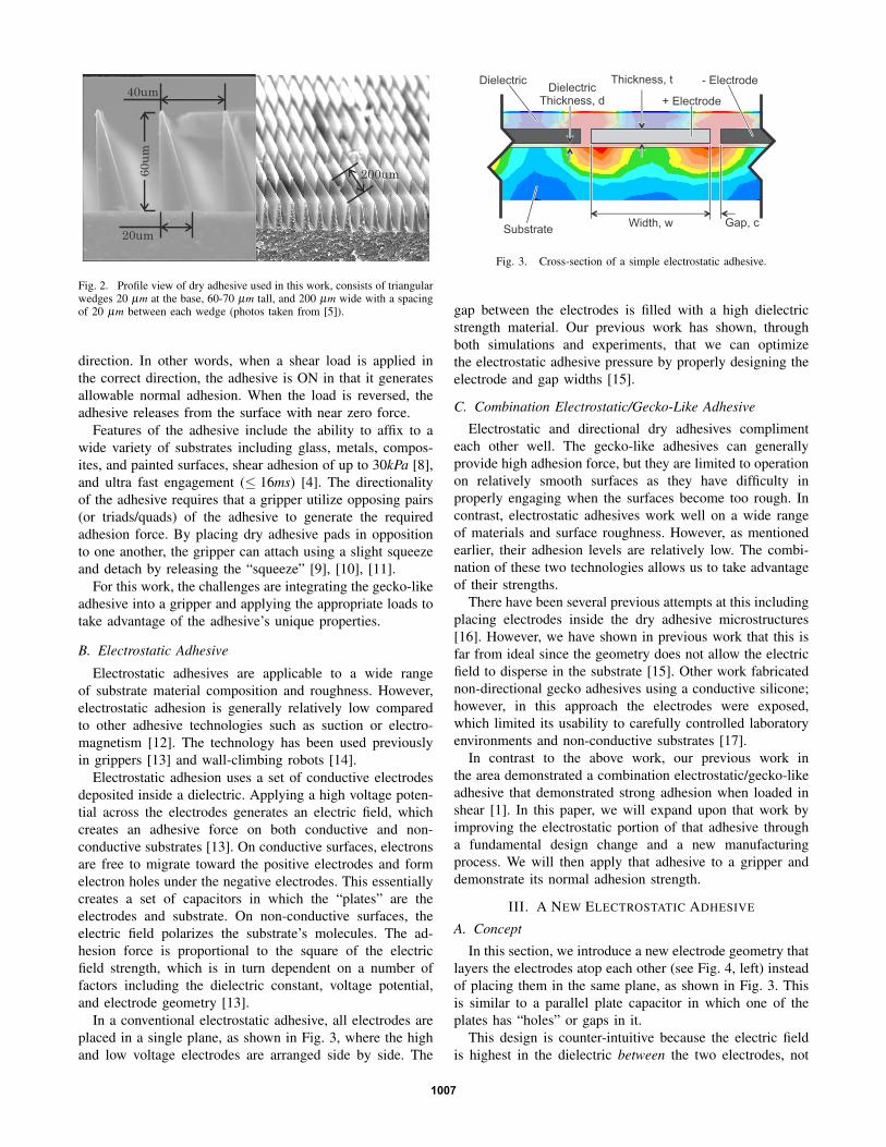
Since the early 2000s, numerous researchers have builtartificial dry adhesives inspired by geckos [6], [7]. Theadhesives we use in this work are described in detail in [5],where the technical challenges of fabricating the adhesiveshas also largely been addressed. The adhesive itself consistsof triangular wedges 20 µm at the base, 60-70 µm tall, and200 µm wide with a spacing of 20 µm between each wedge(see Fig. 2). Similar to geckos, the adhesive is directional inthat it uses asymmetric micro-structured hairs that create ahigh real area of contact when loaded in a preferred shear
2016 IEEE/RSJ International Conference on Intelligent Robots and Systems (IROS)Daejeon Convention CenterOctober 9-14, 2016, Daejeon, Korea
978-1-5090-3761-2/16/$31.00 ©2016 IEEE 1006
20um
60um
200um
40um
Fig. 2. Profile view of dry adhesive used in this work, consists of triangularwedges 20 µm at the base, 60-70 µm tall, and 200 µm wide with a spacingof 20 µm between each wedge (photos taken from [5]).
direction. In other words, when a shear load is applied inthe correct direction, the adhesive is ON in that it generatesallowable normal adhesion. When the load is reversed, theadhesive releases from the surface with near zero force.
Features of the adhesive include the ability to affix to awide variety of substrates including glass, metals, compos-ites, and painted surfaces, shear adhesion of up to 30kPa [8],and ultra fast engagement (≤ 16ms) [4]. The directionalityof the adhesive requires that a gripper utilize opposing pairs(or triads/quads) of the adhesive to generate the requiredadhesion force. By placing dry adhesive pads in oppositionto one another, the gripper can attach using a slight squeezeand detach by releasing the “squeeze” [9], [10], [11].
For this work, the challenges are integrating the gecko-likeadhesive into a gripper and applying the appropriate loads totake advantage of the adhesive’s unique properties.
B. Electrostatic Adhesive
Electrostatic adhesives are applicable to a wide rangeof substrate material composition and roughness. However,electrostatic adhesion is generally relatively low comparedto other adhesive technologies such as suction or electro-magnetism [12]. The technology has been used previouslyin grippers [13] and wall-climbing robots [14].
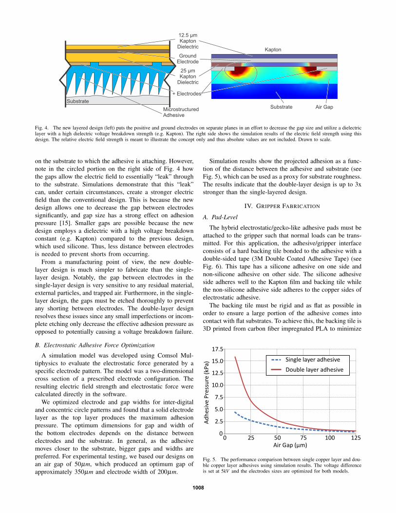
Electrostatic adhesion uses a set of conductive electrodesdeposited inside a dielectric. Applying a high voltage poten-tial across the electrodes generates an electric field, whichcreates an adhesive force on both conductive and non-conductive substrates [13]. On conductive surfaces, electronsare free to migrate toward the positive electrodes and formelectron holes under the negative electrodes. This essentiallycreates a set of capacitors in which the “plates” are theelectrodes and substrate. On non-conductive surfaces, theelectric field polarizes the substrate’s molecules. The ad-hesion force is proportional to the square of the electricfield strength, which is in turn dependent on a number offactors including the dielectric constant, voltage potential,and electrode geometry [13].
In a conventional electrostatic adhesive, all electrodes areplaced in a single plane, as shown in Fig. 3, where the highand low voltage electrodes are arranged side by side. The
Dielectric
Substrate
+ Electrode
- Electrode
Gap, cWidth, w
Thickness, tDielectric
Thickness, d
Fig. 3. Cross-section of a simple electrostatic adhesive.
gap between the electrodes is filled with a high dielectricstrength material. Our previous work has shown, throughboth simulations and experiments, that we can optimizethe electrostatic adhesive pressure by properly designing theelectrode and gap widths [15].
C. Combination Electrostatic/Gecko-Like Adhesive
Electrostatic and directional dry adhesives complimenteach other well. The gecko-like adhesives can generallyprovide high adhesion force, but they are limited to operationon relatively smooth surfaces as they have difficulty inproperly engaging when the surfaces become too rough. Incontrast, electrostatic adhesives work well on a wide rangeof materials and surface roughness. However, as mentionedearlier, their adhesion levels are relatively low. The combi-nation of these two technologies allows us to take advantageof their strengths.
There have been several previous attempts at this includingplacing electrodes inside the dry adhesive microstructures[16]. However, we have shown in previous work that this isfar from ideal since the geometry does not allow the electricfield to disperse in the substrate [15]. Other work fabricatednon-directional gecko adhesives using a conductive silicone;however, in this approach the electrodes were exposed,which limited its usability to carefully controlled laboratoryenvironments and non-conductive substrates [17].
In contrast to the above work, our previous work inthe area demonstrated a combination electrostatic/gecko-likeadhesive that demonstrated strong adhesion when loaded inshear [1]. In this paper, we will expand upon that work byimproving the electrostatic portion of that adhesive througha fundamental design change and a new manufacturingprocess. We will then apply that adhesive to a gripper anddemonstrate its normal adhesion strength.
III. A NEW ELECTROSTATIC ADHESIVE
A. Concept
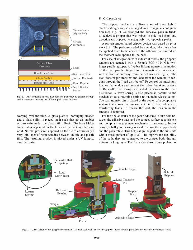
In this section, we introduce a new electrode geometry thatlayers the electrodes atop each other (see Fig. 4, left) insteadof placing them in the same plane, as shown in Fig. 3. Thisis similar to a parallel plate capacitor in which one of theplates has “holes” or gaps in it.
This design is counter-intuitive because the electric fieldis highest in the dielectric between the two electrodes, not
1007
25 μmKapton
Dielectric
Substrate
+ Electrodes
GroundElectrode
12.5 μmKapton
Dielectric
MicrostructuredAdhesive
Kapton
Air GapSubstrate
Fig. 4. The new layered design (left) puts the positive and ground electrodes on separate planes in an effort to decrease the gap size and utilize a dielectriclayer with a high dielectric voltage breakdown strength (e.g. Kapton). The right side shows the simulation results of the electric field strength using thisdesign. The relative electric field strength is meant to illustrate the concept only and thus absolute values are not included. Drawn to scale.
on the substrate to which the adhesive is attaching. However,note in the circled portion on the right side of Fig. 4 howthe gaps allow the electric field to essentially “leak” throughto the substrate. Simulations demonstrate that this “leak”can, under certain circumstances, create a stronger electricfield than the conventional design. This is because the newdesign allows one to decrease the gap between electrodessignificantly, and gap size has a strong effect on adhesionpressure [15]. Smaller gaps are possible because the newdesign employs a dielectric with a high voltage breakdownconstant (e.g. Kapton) compared to the previous design,which used silicone. Thus, less distance between electrodesis needed to prevent shorts from occurring.
From a manufacturing point of view, the new double-layer design is much simpler to fabricate than the single-layer design. Notably, the gap between electrodes in thesingle-layer design is very sensitive to any residual material,external particles, and trapped air. Furthermore, in the single-layer design, the gaps must be etched thoroughly to preventany shorting between electrodes. The double-layer designresolves these issues since any small imperfections or incom-plete etching only decrease the effective adhesion pressure asopposed to potentially causing a voltage breakdown failure.
B. Electrostatic Adhesive Force Optimization
A simulation model was developed using Comsol Mul-tiphysics to evaluate the electrostatic force generated by aspecific electrode pattern. The model was a two-dimensionalcross section of a prescribed electrode configuration. Theresulting electric field strength and electrostatic force werecalculated directly in the software.
We optimized electrode and gap widths for inter-digitaland concentric circle patterns and found that a solid electrodelayer as the top layer produces the maximum adhesionpressure. The optimum dimensions for gap and width ofthe bottom electrodes depends on the distance betweenelectrodes and the substrate. In general, as the adhesivemoves closer to the substrate, bigger gaps and widths arepreferred. For experimental testing, we based our designs onan air gap of 50µm, which produced an optimum gap ofapproximately 350µm and electrode width of 200µm.
Simulation results show the projected adhesion as a func-tion of the distance between the adhesive and substrate (seeFig. 5), which can be used as a proxy for substrate roughness.The results indicate that the double-layer design is up to 3xstronger than the single-layered design.
IV. GRIPPER FABRICATION
A. Pad-Level
The hybrid electrostatic/gecko-like adhesive pads must beattached to the gripper such that normal loads can be trans-mitted. For this application, the adhesive/gripper interfaceconsists of a hard backing tile bonded to the adhesive with adouble-sided tape (3M Double Coated Adhesive Tape) (seeFig. 6). This tape has a silicone adhesive on one side andnon-silicone adhesive on other side. The silicone adhesiveside adheres well to the Kapton film and backing tile whilethe non-silicone adhesive side adheres to the copper sides ofelectrostatic adhesive.
The backing tile must be rigid and as flat as possible inorder to ensure a large portion of the adhesive comes intocontact with flat substrates. To achieve this, the backing tile is3D printed from carbon fiber impregnated PLA to minimize
0
2.5
5.0
7.5
10.0
12.5
15.0
17.5
0 25 50 75 100 125
Ad
hes
ive
Pre
ssu
re (
kPa)
Air Gap (µm)
Single layer adhesive
Double layer adhesive
Fig. 5. The performance comparison between single copper layer and dou-ble copper layer adhesives using simulation results. The voltage differenceis set at 5kV and the electrodes sizes are optimized for both models.
1008
Carbon Fiber Hardback Resin
Top Electrodes
50μm Kapton Bottom Electrode
Dry Adhesive Stalks
25μm Kapton
Double side Tape
Double side Tape
VoltageTerminals
Connection togripper body
Fig. 6. An electrostatic/gecko-like adhesive pad ready to assembled (top)and a schematic showing the different pad layers (bottom).
warping over the time. A glass plate is thoroughly cleanedand a plastic film is placed on it such that no air bubblesor dust exist under the plastic film. Resin (G+ from MakerJuice Labs) is poured on the film and the backing tile is seton it. Normal pressure is applied on the tile to ensure only avery thin layer of resin remains between the tile and plasticfilm. The resulting product is placed under a UV lamp tocure the resin.
B. Gripper-Level
The gripper mechanism utilizes a set of three hybridelectrostatic-gecko pads arranged in a triangular configura-tion (see Fig. 7) We arranged the adhesive pads in triadsto achieve a gripper that was robust to side load from anydirection (as opposed to using only two opposing pads).
A proven tendon-based gripper design was based on priorwork [18]. The pads are loaded by a tendon, which transfersthe applied force to the center of the adhesive pads to reducethe moment load applied to the pads.
For ease of integration with industrial robots, the gripper’stendons are actuated with a Schunk EGP 40-N-N-B two-finger parallel gripper. A five-bar linkage transfers the motionof the two parallel fingers into kinematically constrainedvertical translation away from the Schunk (see Fig. 7). Theload transfer pin transfers the load from the Schunk to ten-dons through the “load distributor.” To control the maximumload on the tendon and prevent them from breaking, a stackof Belleville disc springs are added in series to the loaddistributor. A wave spring is also placed in parallel to themechanism as a returning spring to maintain release action.The load transfer pin is placed at the center of a compliancesystem that allows the engagement pin to float while alsotransferring loads. To release the load, the tension in thetendons is removed.
For the fibular stalks of the gecko adhesive to take hold be-tween the adhesive pads and the contact surface, a consistentand compliant engagement mechanism is necessary. In ourdesign, a ball joint bearing is used to allow the gripper bodyand the pads rotate. This helps align the pads to the substratewith a misalignment of up to 20◦. To improve the flexibilityof the pads, they are connected to the gripper body througha foam backing layer. The foam also absorbs any preload as
Schunk Gripper
Adhesive Pads
Gripper Body
Return Spring
Belleville Disk Springs
Foam
Load Transfer Pin
5bar LinkageLoad
Distributor
Ball JointBearing
Tendon
Fig. 7. CAD design of the gripper mechanism. The half sectional view of the gripper shows internal parts and the way the mechanism works
1009

Converter
Test Substrate
GripperLabviewUser Interface
Data AcquisitionBoard
Force Sensor(not visible)
Fig. 8. Experimental Setup
0.0
1.0
2.0
3.0
4.0
5.0
6.0
No
rmal
Ad
hes
ion
Pre
ssu
re (
kPa)
Acr
ylic
Carb
on F
iber
Gla
ssFi
berg
lass
ABS
Poly
este
rCe
real
Box
Pap
er
Corr
ugat
ed C
ardb
oard
Gecko Only
Gecko & Electroadhesion
Fig. 9. Experimental evaluation of the gripper on rigid substrates
the gripper engages with the substrate.
V. EXPERIMENTAL EVALUATION
A prototype gripper was experimentally validated to char-acterize the normal adhesion force and also demonstraterepeated usage in an industrial setting.
A. Adhesion Characterization
Gripper characterization experiments were conducted us-ing the test set-up shown in Fig. 8. In the experiments, theelectrostatic adhesive was activated using a 6kV potentialgenerated with an EMCO CB101 DC-DC high voltageconverter. Note that because of difficulties in modeling thesurface roughness of the substrate materials, we do notdirectly compare the simulation results with the experimentalresults. Instead, the experimental results are designed todemonstrate the overall effectiveness of the gripper.
The experimental procedure is as follows:1) Attach the test material to wooden backing plate and
place on a JR3 force/torque sensor. If the test samplewas flexible (e.g. a fabric), then only the outer edgeof the sample was taped to the wooden backing plate.
0.0
0.5
1.0
1.5
2.0
2.5
3.0
3.5
4.0
No
rmal
Ad
hes
ion
Pre
ssu
re (
kPa)
Gecko Only
Gecko & Electroadhesion
Fibe
rgla
ss F
abri
cTy
vek
Brow
n Fi
lter F
abri
c
Rips
top
Silv
er F
abri
cSh
ield
ing
Fabr
ic69
µm
Fab
ric
Whi
te F
abri
cCo
tton
Myl
arKa
pton
Fig. 10. Experimental evaluation of the gripper on flexible substrates. Pho-tographs of substrates whose descriptions may be ambiguous are included.
We recognize that in the case of flexible samples, thisapproach is not ideal since in an industrial setting, mostfabrics would be loose. However, we used this ap-proach because it can quickly and effectively quantifythe normal adhesion pressure for a particular fabric.
2) Place the gripper on the sample by hand and applyenough preload to ensure that all pads are in contactwith the sample substrate.
3) Actuate the Schunk to engage the gecko-like adhesive.4) Turn on the high voltage DC-DC converter.5) Pull the gripper vertically from the substrate by hand.6) Measure the resulting force profile with Labview.
The maximum adhesion pressure of the gripper is calculatedby dividing the maximum force from sensor data by the totalsurface area of the three pads. We performed ten tests foreach sample. Figures 9 and 10 illustrate the median value ofnormal adhesion pressure for the gripper using the combinedelectrostatic/gecko-like adhesive and a gecko-like adhesivealone as a control. The error bars represent the 1st and 3rdquartile of the results.
The results show that the electrostatic adhesion improvesthe gripper performance in almost all cases, and its effect onflexible samples is quiet pronounced. The only exception isMylar, but we have no clear explanation for this anomaly atthis time. Also note that the repeatability of the experiments,as represented by the error bars, is a reflection of the factthat these tests were performed manually.
B. Performance Evaluation on Industrial Robot Arm
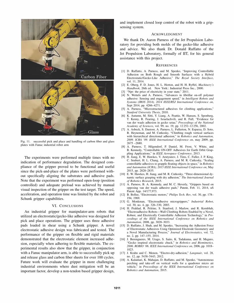
To demonstrate the usability of the gripper in an industrialsetting, we mounted the gripper to a Fanuc LR Mate 200icmanipulator arm and performed more than 100 repeated pick-and-place operations. The gripper successfully performedthis material handling exercise with both glass and carbonfiber plates (see Fig. 11).
1010
Carbon Fiber
Glass
Fig. 11. successful pick and place and handling of carbon fiber and glassplates with Fanuc industrial robot arm
The experiments were performed multiple times with noindication of performance degradation. The designed com-pliance of the gripper proved to be functional and usefulsince the pick-and-place of the plates were performed with-out specifically aligning the substrates and adhesive pads.Note that the experiment was performed open-loop (positioncontrolled) and adequate preload was achieved by manualvisual inspection of the gripper on the test target. The speed,acceleration, and operation time was limited by the robot andSchunk gripper capabilities.
VI. CONCLUSIONS
An industrial gripper for manipulator-arm robots thatutilized an electrostatic/gecko-like adhesive was designed forpick and place operations. The gripper uses three adhesivepads loaded in shear using a Schunk gripper. A novelelectrostatic adhesive design was fabricated and tested. Theperformance of the gripper on flexible and rigid materialsdemonstrated that the electrostatic element increased adhe-sion, especially when adhering to flexible materials. The ex-perimental results also show that the gripper, in conjunctionwith a Fanuc manipulator arm, is able to successfully pick upand release glass and carbon fiber sheets for over 100 cycles.Future work will evaluate the gripper in more challengingindustrial environments where dust mitigation will be animportant factor, develop a non-tendon based gripper design,
and implement closed loop control of the robot with a grip-sensing system.
ACKOWLEDGMENT
We thank Dr. Aaron Parness of the Jet Propulsion Labo-ratory for providing both molds of the gecko-like adhesiveand advice. We also thank Dr. Donald Ruffatto of theJet Propulsion Laboratory, formally of IIT, for his generalassistance with this project.
REFERENCES
[1] D. Ruffatto, A. Parness, and M. Spenko, “Improving ControllableAdhesion on Both Rough and Smooth Surfaces with a HybridElectrostatic/Gecko-Like Adhesive,” The Royal Society Interface,vol. 11, 2014.
[2] E. Oberg, F. D. Jones, H. L. Horton, and H. H. Ryffel, Machinery’sHandbook, 26th ed. New York:: Industrial Press Inc., 2000.
[3] “Npr: the price of electricity in your state,” 2011.[4] N. Wettels and A. Parness, “Advances in fibrillar on-off polymer
adhesive: Sensing and engagement speed,” in Intelligent Robots andSystems (IROS 2014), 2014 IEEE/RSJ International Conference on,Sept 2014, pp. 4266–4271.
[5] A. Parness, “Microstructured adhesives for climbing applications,”Stanford University Thesis, 2010.
[6] K. Autumn, M. Sitti, Y. Liang, A. Peattie, W. Hansen, S. Sponberg,T. Kenny, R. Fearing, J. Israelachvili, and R. Full, “Evidence forvan der waals adhesion in gecko setae,” Proceedings of the NationalAcademy of Sciences, vol. 99, no. 19, pp. 12 252–12 256, 2002.
[7] A. Asbeck, S. Dastoor, A. Parness, L. Fullerton, N. Esparza, D. Soto,B. Heyneman, and M. Cutkosky, “Climbing rough vertical surfaceswith hierarchical directional adhesion,” in Robotics and Automation,2009. ICRA ’09. IEEE International Conference on, may 2009, pp.2675 –2680.
[8] A. Parness, T. Hilgendorf, P. Daniel, M. Frost, V. White, andB. Kennedy, “Controllable ON-OFF Adhesives for Earth Orbit Grap-pling Applications,” in IEEE Aerospace Conference, 2013.
[9] H. Jiang, E. W. Hawkes, V. Arutyunov, J. Tims, C. Fuller, J. P. King,C. Seubert, H. L. Chang, A. Parness, and M. R. Cutkosky, “Scalingcontrollable adhesives to grapple floating objects in space,” in Roboticsand Automation (ICRA), 2015 IEEE International Conference on, May2015, pp. 2828–2835.
[10] E. W. Hawkes, H. Jiang, and M. R. Cutkosky, “Three-dimensional dy-namic surface grasping with dry adhesion,” The International Journalof Robotics Research, 2015.
[11] A. Parness, B. A. Kennedy, and M. C. Heverly, “Grippers based onopposing van der waals adhesive pads,” Patent, Feb. 11, 2014, uSPatent App. 14/177,973.
[12] B. Bollee, “Electrostatic motors,” Philips Tech. Rev, vol. 30, pp. 178–194, 1969.
[13] G. Monkman, “Electroadhesive microgrippers,” Industrial Robot,vol. 30, no. 4, pp. 326–330, 2003.
[14] H. Prahlad, R. Pelrine, S. Stanford, J. Marlow, and R. Kornbluh,“Electroadhesive Robots—Wall Climbing Robots Enabled by a Novel,Robust, and Electrically Controllable Adhesion Technology,” in Pro-ceedings of the IEEE International Conference on Robotics andAutomation, 2008, pp. 3028–3033.
[15] D. Ruffatto, J. Shah, and M. Spenko, “Increasing the Adhesion Forceof Electrostatic Adhesives Using Optimized Electrode Geometery anda Novel Manufacturing Process,” Journal of Electrostatics, vol. 72,no. 2, pp. 147–155, 2014.
[16] J. Berengueres, M. Urago, S. Saito, K. Tadakuma, and H. Meguro,“Gecko inspired electrostatic chuck,” in Robotics and Biomimetics,2006. ROBIO ’06. IEEE International Conference on, 2006, pp. 1018–1023.
[17] J. Krahn and C. Menon, “Electro-dry-adhesion,” Langmuir, vol. 28,no. 12, pp. 5438–5443, 2012.
[18] A. Kalantari, K. Mahajan, D. Ruffatto, and M. Spenko, “Autonomousperching and take-off on vertical walls for a quadrotor micro airvehicle,” in Proceedings of the IEEE International Conference onRobotics and Automation, 2015.
1011