a simple algorithm for analyzing a piled raft by ... · a simple algorithm for analyzing a piled...
TRANSCRIPT

Civil Engineering Infrastructures Journal, 47(2): 215 – 227, December 2014
ISSN: 2322 – 2093
* Corresponding author E-mail: [email protected]
215
A Simple Algorithm for Analyzing a Piled Raft by Considering Stress
Distribution
Saeedi Azizkandi, A.R.1*
and Fakher, A.2
1
Ph.D. Candidate, Department of Civil Engineering, Iran University of Science and
Technology, Tehran, Iran. 2
Associate Professor, School of Civil Engineering, College of Engineering, University of
Tehran, P.O.Box: 11155-4563, Tehran, Iran.
Received: 26 Nov. 2012; Revised: 21 Sep. 2013; Accepted: 30 Sep. 2013
ABSTRACT: Numerous techniques have been presented by different researchers to
analyze piled raft. In order to analyze pile foundation, soil can be modeled as spring,
continuous medium, or porous media. Pile can also be modeled as spring or continuous
medium. This study includes three main stages: a short description of different types of
analysis methods of pile foundation, writing a computer program based on the finite
element method (FEM) for analyzing piled raft foundation (in this program, foundation is
modeled as a flexible plate, soil and pile are modeled by Winkler springs), and comparison
of different concepts of pile group design.
Keywords: Interaction, Piled Raft Foundation, Settlement, Stress Distribution, Winkler
Spring.
INTRODUCTION
In order to build a structure, it is required to
use a foundation to transfer applied load to
soil. As well as load transfer function,
foundations should be designed in a way that
produced settlements, including uniform and
non-uniform settlement, do not exceed the
allowable limit.
Most of old buildings were built on a strip
footing or single footing and if the ground
surface layer were loose and compressible,
timber pile would be used because of low
wages and abundant wood resources. In
addition, charcoal was used to provide
abuoyant resistant layer in slough areas.
However, as the weight and rigidity of
buildings increased, in the eighteenth
century, and also due to economic reasons,
these methods, particularly timber piles,
gradually lost their importance. In this
condition, piles were used beneath the
shallow foundation, where shallow
foundation failed to resist applied load or
where settlements exceeded the allowable
limit.
The analysis of pile group behavior is
conducted by making two basic
assumptions, i.e. piled raft (free pile group)
and free standing pile group. The first
assumption leads to unreal increase of axial
forces in the piles, while it is possible to
design piles for fewer forces through
considering the role of pile cap. If the soil
below shallow foundation is loose or is
affected by scouring, load-bearing share can
Saeedi Azizkandi, A.R. and Fakher, A.
216
be ignored and the total load will be
undertaken by piles. The assumption of free
pile group seems to be rational in such
situations, whereas if the soil bellow the
foundation is resistant, pile cap cooperates
with piles to transfer load and a percentage
of the load will be transferred by shallow
foundation and the remainder by piles. Due
to economic importance, this topic has been
the focus of attention by various researchers
and, consequently, different numerical
programs have been developed in order to
analyze the pile foundation.
ANALYSIS METHODS OF PILE
GROUP
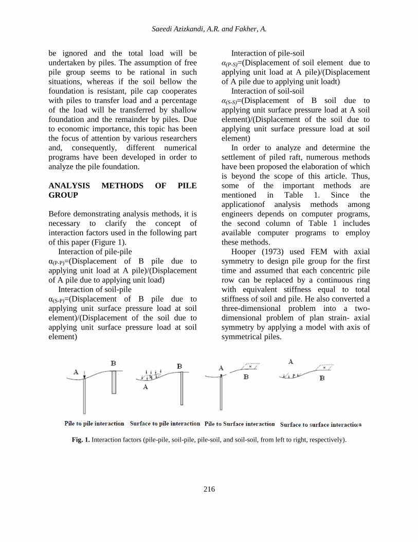
Before demonstrating analysis methods, it is
necessary to clarify the concept of
interaction factors used in the following part
of this paper (Figure 1).
Interaction of pile-pile
α(P-P)=(Displacement of B pile due to
applying unit load at A pile)/(Displacement
of A pile due to applying unit load)
Interaction of soil-pile
α(S-P)=(Displacement of B pile due to
applying unit surface pressure load at soil
element)/(Displacement of the soil due to
applying unit surface pressure load at soil
element)
Interaction of pile-soil
α(P-S)=(Displacement of soil element due to
applying unit load at A pile)/(Displacement
of A pile due to applying unit loadt)
Interaction of soil-soil
α(S-S)=(Displacement of B soil due to
applying unit surface pressure load at A soil
element)/(Displacement of the soil due to
applying unit surface pressure load at soil
element)
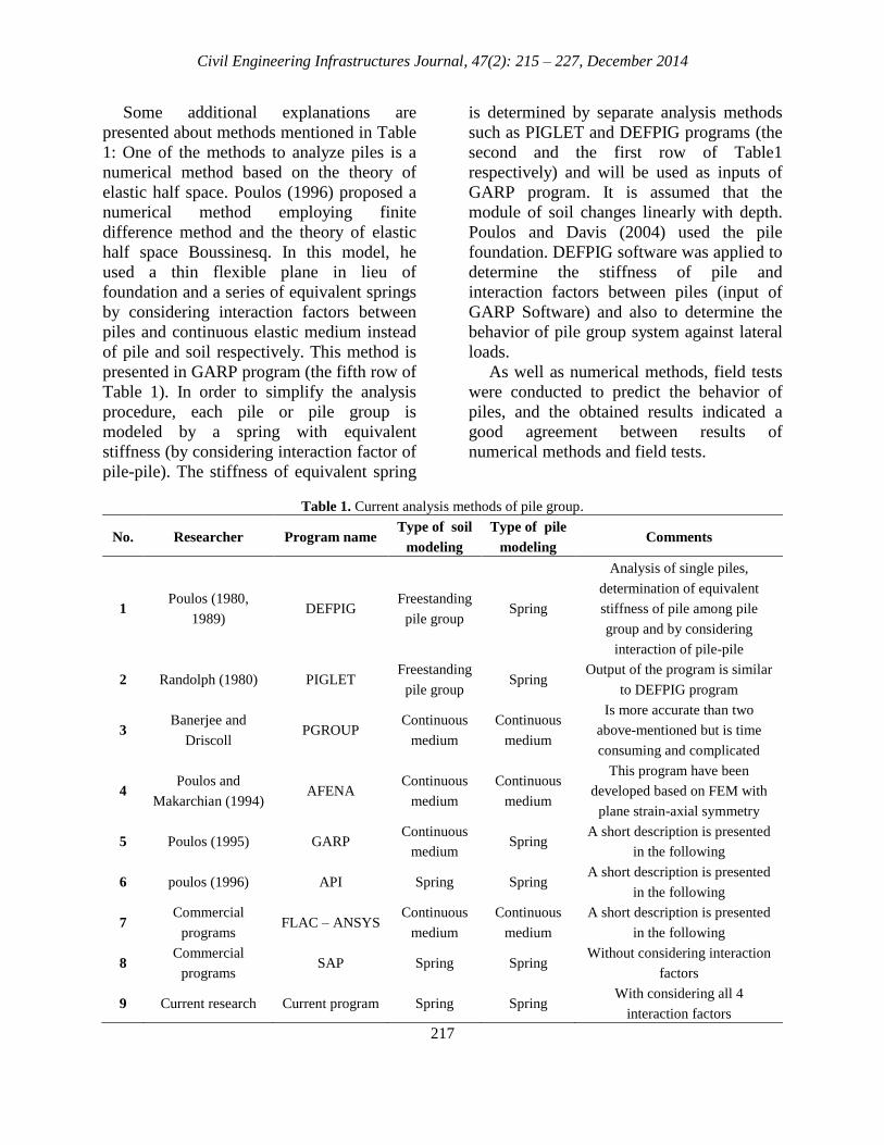
In order to analyze and determine the
settlement of piled raft, numerous methods
have been proposed the elaboration of which
is beyond the scope of this article. Thus,
some of the important methods are
mentioned in Table 1. Since the
applicationof analysis methods among
engineers depends on computer programs,
the second column of Table 1 includes
available computer programs to employ
these methods.
Hooper (1973) used FEM with axial
symmetry to design pile group for the first
time and assumed that each concentric pile
row can be replaced by a continuous ring
with equivalent stiffness equal to total
stiffness of soil and pile. He also converted a
three-dimensional problem into a two-
dimensional problem of plan strain- axial
symmetry by applying a model with axis of
symmetrical piles.
Fig. 1. Interaction factors (pile-pile, soil-pile, pile-soil, and soil-soil, from left to right, respectively).
Civil Engineering Infrastructures Journal, 47(2): 215 – 227, December 2014
217
Some additional explanations are
presented about methods mentioned in Table
1: One of the methods to analyze piles is a
numerical method based on the theory of
elastic half space. Poulos (1996) proposed a
numerical method employing finite
difference method and the theory of elastic
half space Boussinesq. In this model, he
used a thin flexible plane in lieu of
foundation and a series of equivalent springs
by considering interaction factors between
piles and continuous elastic medium instead
of pile and soil respectively. This method is
presented in GARP program (the fifth row of
Table 1). In order to simplify the analysis
procedure, each pile or pile group is
modeled by a spring with equivalent
stiffness (by considering interaction factor of
pile-pile). The stiffness of equivalent spring
is determined by separate analysis methods
such as PIGLET and DEFPIG programs (the
second and the first row of Table1
respectively) and will be used as inputs of
GARP program. It is assumed that the
module of soil changes linearly with depth.
Poulos and Davis (2004) used the pile
foundation. DEFPIG software was applied to
determine the stiffness of pile and
interaction factors between piles (input of
GARP Software) and also to determine the
behavior of pile group system against lateral
loads.
As well as numerical methods, field tests
were conducted to predict the behavior of
piles, and the obtained results indicated a
good agreement between results of
numerical methods and field tests.
Table 1. Current analysis methods of pile group.
No. Researcher Program name Type of soil
modeling
Type of pile
modeling Comments
1 Poulos (1980,
1989) DEFPIG
Freestanding
pile group Spring
Analysis of single piles,
determination of equivalent
stiffness of pile among pile
group and by considering
interaction of pile-pile
2 Randolph (1980) PIGLET Freestanding
pile group Spring
Output of the program is similar
to DEFPIG program
3 Banerjee and
Driscoll PGROUP
Continuous
medium
Continuous
medium
Is more accurate than two
above-mentioned but is time
consuming and complicated
4 Poulos and
Makarchian (1994) AFENA
Continuous
medium
Continuous
medium
This program have been
developed based on FEM with
plane strain-axial symmetry
5 Poulos (1995) GARP Continuous
medium Spring
A short description is presented
in the following
6 poulos (1996) API Spring Spring A short description is presented
in the following
7 Commercial
programs FLAC – ANSYS
Continuous
medium
Continuous
medium
A short description is presented
in the following
8 Commercial
programs SAP Spring Spring
Without considering interaction
factors
9 Current research Current program Spring Spring With considering all 4
interaction factors

Saeedi Azizkandi, A.R. and Fakher, A.
218
The principle of method used in API
program (the sixth row of Table 1) was
suggested by Poulos (1996). In this method,
the first step is to determine the stiffness of
foundation, pile and pile foundation. Then,
the total load (Pt) will be distributed
according to the stiffness of elements, and
the settlement of piled raft will be
determined. API uses the following
equations to determine the above-mentioned
parameters.
Pile stiffness: In order to determine pile
stiffness, the proposed equation by Randolph
(1987) is used.
Pile group stiffness: According to the
stiffness of a single pile, pile group stiffness
is calculated by Eq.1 proposed by Randolph
(1987):
(1)
where KPG, KP, n, and W are pile group
stiffness, single pile stiffness, the number of
piles forming pile group, and a factor related
to type and distance between piles
respectively. Poulos (1989) suggested the
value of 0.3 to 0.5 for W.
Interaction factors: Interaction factors
between pile group and mat foundation (αpr
and αrp) are calculated by Eq.2.
⁄
⁄
(2)
where Kr and rm are total stiffness of the
foundation and effect radius of produced
shear stress respectively; and are calculated
by the following equations.
( )
(3)
(4)
where E, t, νr and ρ are Young module,
thickness, Poisson's ratio of foundation and
⁄ are change of shear module
with soil depth respectively.
Pile foundation stiffness: regarding the
stiffness of foundation and pile group and
using proposed equations by Randolph and
Wroth (1993), the stiffness of pile
foundation and load-bearing share of
foundation and pile group are calculated.
During recent years, full modeling of pile
group, soil and pile cap by FEM has been
the focus of attention due to increase of
computational ability of computers.
Although most of the methods deal with
linear analysis, FEM showed comprehensive
results in comparison to other methods. It
should be noted that most of FEM were
conducted in two dimensions, and three-
dimensional analyses were avoided because
they were time-consuming, particularly, in
non-linear analysis. However, three-
dimensional modeling of pile group and soil
by FEM is common in research projects.
THE PROPOSED LINEAR ANALYSIS
ALGORITHM OF PILED RAFT
FOUNDATION
Idealization of Foundation, Soil and Pile
A program was developed based on FEM
in Fortran Programming Language to
determine settlement and load-bearing share
of foundation and piles. In this program,
foundation is modeled by a flexible plane
with 4-node elements, and soil and piles are
modeled by Winkler springs (Figure 2).
Separated equation of stiffness of pile
foundation based on FEM is as follows:
(5)
Kp, Ks, Kr, and K are stiffness matrixes of
pile, soil, flexible plate and total stiffness
respectively and are determined as follows:

Civil Engineering Infrastructures Journal, 47(2): 215 – 227, December 2014
219
Fig. 2. FEM of a piled raft foundation.
Stiffness Matrix of Flexible Plate
In order to determine the stiffness matrix
of a 4-node flexible plane, in which
deflection of nodes includes vertical
deflection (W) and rotation in the direction
of x, y axis (θx, θy) (Figure 3), the following
equation may be used:
∑ ∫
(6)
where ∑, A, B, and D are sum operator, the
area of one element, matrix of relation
between deflection and strain, and matrix of
characteristics of flexible plane respectively.
The result of the above integration is Kr
element presented in the following equation
and matrix:
Fig. 3. Rectangular flexible element with freedom
degree of 12
Stiffness Matrix of Piles by Considering
Interaction between Pile-Pile and Pile-Soil
In order to determine the stiffness matrix
of piles and stress distribution around each
pile, it is essential to evaluate stiffness and
stress distribution of pile shaft and pile base
separately (Figure 4).
(7)
1
22
1 2 1
1 11,1
24,2 2,1 2,2
2 14,3 5,3 3,1 3,2 3
60 60 42 12
60 6 24 80 16 16
60 6 24 60 80 16 16
30 60 42 12 30 6 24 60 6 6
40 16 16 0
40 4 4
60. .
r
P p
ab P b P P
b
a P ab a P
P P b P a P K
K b P K K Symmetric
K K a P K K KDK
a b
,3
1 110,1 10,2 10,3 1,1
27,2 11,1 11,2 11,3 2,1 2,2
2 17,3 8,3 12,1 12,2 12,3 3,1 3,2 3,3
1 17,1 7,2
30 30 42 12 30 6 6 30 6 6
20 4 4 0
20 4 4
60 30 42 12 60 6 6 30 6 24
P P b P a P K K K K
K b P K K K K K
K K a P K K K K K K
P P b P a P K K
7,3 4,1 4,2 4,3 1,1
210,2 8,1 8,2 8,3 5,1 5,2 5,3 2,1 2,2
2 110,3 11,3 9,1 9,2 9,3 6,1 6,2 6,3 3,1 3,2 3,3
40 4 4 0
40 16 16
K K K K K
K b P K K K K K K K K
K K a P K K K K K K K K K

Saeedi Azizkandi, A.R. and Fakher, A.
220
Fig. 4. Idealized model used in T-Z load transfer analyses.
Determination of the Pile Shaft Stiffness The analysis of finite element method and
boundary element method of friction pile
reaction (Randolph, 1977) showed that load
transfer through shear stresses produced on
the horizontal and vertical planes. In general,
a pile may be considered as an object
surrounded by concentric cylinders of soil.
Shear stress in each cylinder is equal
(Randolph et al., 1978; Frank, 1974). By
cutting sector-shaped pieces from two
adjacent cylinders in soil (Figure 5) and
writing equilibrium equation in the y
direction, we may have:
( )
( )
( ) ( )2
( ) 02
y
y
y
drr
r dr d dy r d dy
drdy r d dr
y
drr d dr
(8)
After simplifying and neglecting the second
order terms, Eq. (8) reduces to:
( )0
yrr
r y
(9)
However, according to Randolph and
Wroth (1978), the rate of change of vertical
stress with respect to depth is much less than
the rate of change of shear stress with
respect to radial distance during axial
loading of pile. Therefore, the second term
of Eq. (9) can be neglected, and the above
equilibrium equation can be approximated
as:
( )0
r
r
(10)
Through integration of Eq. (10) and based
on the assumption of homogeneous and
elastic soil:
0
0 0
0 0 0 0
( ) 0 ( ) ( )
( )0 ( )
r
rd r r r r r
r r rr
r r
(11)
where 𝜏 ),𝜏 𝜏 and are shear stress
applied in the distance of r from the pile,
produced shear stress between pile, soil, and
pile radius respectively. The relation
between shear stress and strain for linearly
elastic soils is as follows:

Civil Engineering Infrastructures Journal, 47(2): 215 – 227, December 2014
221
Fig. 5. Concentric cylinder model for settlement analysis of axially loaded piles.
γ
τ
(12)
where W is vertical deflection in the distance
of r from pile. Through integration of Eq.
(12), deflection of pile shaft can be
determined by Eq. (13). Change chart of T-Z
is presented in Figure 6.
0
0 00 0
0
( )mr ms
r
r rd rw r Ln
G r G r
(13)
Determination of the Pile Base Stiffness At the base pile, it is sufficient to ignore
the pile shaft and surrounding soil, and treat
the base as rigid punch acting at the surface
of soil medium (in reality, it starts at the
depth z=l). The deflection is obtained from
Boussinesq equation (Eq. (14)). Change
chart of Qb-Z is presented in Figure 7.
(14)
Fig. 6. Stiffness of pile shaft and change of shear stress along pile length.

Saeedi Azizkandi, A.R. and Fakher, A.
222
Fig. 7. Stiffness of pile base and change of bearing capacity of base by increase of pile length.
Based on what was mentioned, the sum
of base settlement and pile axis settlement is
equal to settlement of pile crest (Wt).
Therefore, total load (Pt) may be written as
follows:
(
) (15)
Hence, non-dimensional stiffness of a
rigid pile can be calculated by using the
following equation:
(16)
Most of the piles show some axial
compressibility due to the allowable load,
and this should be considered during the
calculation of pile stiffness. Thus, non-
dimensional stiffness of pile is:
(17)
where ⁄ (ratio of diameter increase
for piles), ⁄ , ⁄ (changes
of shear module with depth), ⁄ (ratio of stiffness of soil to pile),
⁄ , √
(pile
compressibility). In this program, if the
value of
is less than √ ⁄ , piles
will be considered to be rigid and their
stiffness will be calculated by using Eq. (16).
Furthermore, if
is greater than √ ⁄ ,
the value of will approach unit
and Eq. (17) will be approximately
converted into Eq. (18).
√
(18)
and if s s
0
l0.5 E / G 3 E / G
rp p ,
Eq.17 will be used to determine pile
stiffness. If load P is located on a pile, the
deflection of a node in the distance of r from
the load will be calculated by using Eqs. (19-
20).
Civil Engineering Infrastructures Journal, 47(2): 215 – 227, December 2014
223
(19)
⁄
(20)
The ratio of bearing capacity of pile base
(Pb) to total load (Pt) can be determined by
Eq. (21).
(21)
Eqs. (19-21), the value of softness, due to
interaction factors of pile-pile and pile-soil,
is determined by using Eq. (22).
⁄
(22)
The Stiffness Matrix of Soil Concerning
Interaction of Soil-Soil and Soil-Pile The stiffness matrix of soil concerned as
Winkler spring is calculated through the
following equation regardless of interaction.
∑∫ ́
(23)
where Ks is Winkler springs constant factor
and is determined by the proposed equation:
(24)
where Gs, , and B are shear module,
Poisson's ratio of soil, and foundation width
respectively. The softness, due to interaction factors of
soil-soil and soil-pile, is calculated based on
the Boussinesq equation as follows:
(25)
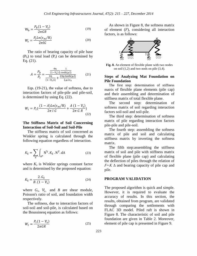
As shown in Figure 8, the softness matrix
of element (F), considering all interaction
factors, is as follows:
Fig. 8. An element of flexible plane with two nodes
on soil (1,2) and two nods on pile (3,4).
Steps of Analyzing Mat Foundation on
Pile Foundation The first step: determination of stiffness
matrix of flexible plane elements (pile cap)
and their assembling and determination of
stiffness matrix of total flexible plane.
The second step: determination of
softness matrix of soil regarding interaction
factors soil-soil and soil-pile.
The third step: determination of softness
matrix of pile regarding interaction factors
pile-pile and pile-soil.
The fourth step: assembling the softness
matrix of pile and soil and calculating
stiffness matrix by inverting the softness
matrix.
The fifth step:assembling the stiffness
matrix of soil and pile with stiffness matrix
of flexible plane (pile cap) and calculating
the deflection of piles through the relation of
F=K ∆ and bearing capacity of pile cap and
pile.
PROGRAM VALIDATION
The proposed algorithm is quick and simple.
However, it is required to evaluate the
accuracy of results. In this section, the
results, obtained from program, are validated
through comparing the settlements with
FLAC 3D model. Piled raft is shown in
Figure 8. The characteristic of soil and pile
foundation are given in Table 2. Moreover,
element of pile cap is presented in Figure 9.

Saeedi Azizkandi, A.R. and Fakher, A.
224
[
⁄
⁄
⁄
⁄
⁄
⁄
]
Table 2. Characteristics of soil and pile foundation.
Soil Pile and Pile Cap
30 2500 Young module (MPa)
0.35 0.2 Poisson's ratio
33.33 13900 Bulk module (MPa)
11.11 10400 Shear module (MPa)
50 - Cohesion (kPa)
30 - Internal friction angle
(constant)
Fig. 9. Schematic shape of piled raft foundation.
In the current model, dimension of pile
cap is 5.5×7.5 m, pile cap thickness is 1 m,
and diameter and length of employed piles
are 1 and 10 m, respectively. The piles are
located in two rows of three piles. Also,
normal load equal to 5000 kN is distributed
uniformly across the areas of pile. The
results of comparison are presented in Table
3.
According to Table 3, results of the
proposed model have a good agreement with
results obtained from FLAC 3D. However, it
should be noted that the running time of
FLAC 3D model for solving the above
example was about 2 days, whereas the
running time of the proposed program was
about 2 minutes. Thus, the applied algorithm
is quick and simple.
COMPARISON OF CONVENTIONAL
AND NEW VIEWPOINTS PILED RAFT
DESIGN
In the conventional methods of foundation
design, the first step is to control the bearing
capacity and settlement of mat foundation. If
the settlement of mat foundation exceeds the
allowable settlement, pile group will be used
in lieu of mat foundation. Most of the
conventional methods ignore load-bearing
share of pile cap and the number of piles will
carry total load. Therefore, the number of
employed piles is more than required. From
the economic perspective, produced
settlement in the mat foundation should be
limited within the allowable settlement. The
new method for designing of pile group is
called reducing-settlement pile foundation.
Figure 10 shows different concepts of
settlement-load curve for designing of pile
group.
In Figure 10, curve number 1 shows the
behavior of mat foundation (without pile).
Produced settlement is more than the
allowable limit. Therefore, piles are used to
reduce settlement. Curve number 2 shows
the conventional concept in the design of
pile group. In this method, piled raft is
designed in a way that a notable portion of
the load is carried by piles. Curve number 3
represents the application of piles to reduce
settlement.

Civil Engineering Infrastructures Journal, 47(2): 215 – 227, December 2014
225
Table 3. Comparison of results obtained from current program and FLAC 3D model.
Error Percentage of Program
Compared with FLAC 3D Proposed Program FLAC 3D
8.9% 13.2 14.5 Settlement of intermediate piles (cm)
1.6% 12.95 12.6 Settlement of piles (cm)
7% 34% 27% load-bearing share of pile cap
Fig. 10. Different concepts of settlement-load curve to design of pile group.
A Case Study to Compare Two
Viewpoints New and Conventional
In this section, a piled raft load of 30,000
kN, the allowable settlement of 7 cm and a
squared-shaped pile cap and thickness of 1m
are designed by both new and conventional
methods. The characteristics of soil and pile
are given in Table 4.
Table 4. Characteristics of soil and pile.
Soil Pile and cap Specification
13 2500 Young module (MPa)
o.3 0.2 Poisson's ratio
10.83 13900 Bulk module (MPa)
5 10400 Shear module (MPa)
70 - Cohesion (KPa)
5 - Internal friction angle
Shallow Mat Foundation Bearing capacity is calculated based on
the characteristics of soil and Eq. (26):
⇒
⁄
(26)
Furthermore, regarding total load of
30,000 kN, the safety factor is:
⁄
(27)
The obtained safety factor for shallow
foundation is favorable. Shallow foundation
analysis program is used so as to analyze
and determine the settlement in shallow
foundation with characteristics of mentioned
soil. The settlement in the center of shallow
foundation is 12.1 cm which is greater than
the allowable settlement.

Saeedi Azizkandi, A.R. and Fakher, A.
226
Design of Pile Group through
Conventional Method The problem of piled raft with dimension
of 15×15, thickness of 1m, and piles with
diameter and length of 1 and 10 m
respectively, is analyzed. The number of
piles is seven piles in seven rows. Besides,
normal load equal to 30,000 KN is
distributed uniformly across the area of pile,
whether the settlement in the center of pile
cap is determined to be 4.12 cm by using
pile group analysis program. As can been
seen clearly, the value of settlement is by far
less than the allowable settlement (7 cm) and
this , in effect, shows that this method is not
economical.
Design of Pile Group through New Method Due to mentioned load, the settlement
exceeds the allowable limit. Regarding the
concept of reducing-settlement pile
foundation, settlements can be limited within
the allowable range by introducing a number
of piles in center of shallow foundation.
Table 5 presents different types of reducing
produced settlements.
Evidently, it can be seen that piled raft
dimension of 15×15, thickness of 1m, and 25
piles with diameter and length of 1 and 10 m
respectively, can be used to design this
foundation.
All of the models run by FLAC 3D
program and the maximum settlement are
presented in Table 5 and one of these models
is illustrated in Figure 11.
Table 5. Settlement in center of pile cap for different types.
Shallow
foundation
with 25 pile
Shallow
foundation
with 9 pile
Shallow
foundation
with 5 pile
Shallow
foundation
with 1 pile
PROGRAM
Different types
to design by new
method
6.2 7.9 8.3 9.9 Current program Maximum
settlement (cm) 6.72 8.14 8.85 10.2 FLAC3D
Fig. 10. Different concepts of settlement-load curve to design of pile group.

Civil Engineering Infrastructures Journal, 47(2): 215 – 227, December 2014
227
CONCLUSIONS
a. Modeling of soil and pile as springs leads
to favorable results only in the event of
considering interaction factors between
springs.
b. The proposed algorithm and program
have a high degree of accuracy relative to
those analyses that use continuous
medium mechanic and full numerical
modeling.
c. The high speed of the proposed program
is comparable with three-dimensional pile
groups by commercial programs.
d. The design of pile group by new method
(reducing-settlement pile foundation) is
more economical than conventional
methods.
e. Final conclusion: Employing the new
method for pile group design (reducing-
settlement pile foundation) requires using
those programs considering load-bearing
share of soil. The commercial programs
based on continuous media mechanic for
analyzing pile group are not employed
because they are time-consuming.
Analysis of pile group by considering
bearing capacity of soil and pile can be
conducted by the proposed algorithm and
program, and practical designs with new
concepts can be developed.
REFERENCES
Akin, J.E. (1988). Finite element analysis for
undergraduate, Academic Press, London.
Badinlo, B.(2006). “Analysis of mat foundation on
pile and soil and comparison of conventional and
modern viewpoints to design pile group”, M.Sc.
Thesis, College of Engineering, University of
Tehran, Tehran, Iran.
Feleming, W.G.K., Weltman, A.J. and Randolph,
M.F. (2008). Piling Engineering, John Wiley and
Sons, 120p, Surrey University Press, London, UK,
3rd edition.
Ghorbani,A. (1997).“Nonlinear and linear analysis of
interaction between pile foundation and soil and
comparison of analysis methods”, M.Sc. Thesis,
School of Civil Engineering, Iran University of
Science and Technology, Tehran, Iran.
Hooper, J.A. (1973). “Observation on the behavior of
a piled raft foundation in London clay”,
Proceeding of Institution of Civil Engineers,
55(2), 855-877.
Poulos H.G. and Davis, A.J. (2005). “Foundation
design for the Emirates twin tower, Dubai”,
Journal of Geotechnical, 6(42), 716-730.
Poulos, H.G. (1989). “Pile behavior – Theory and
application”, Geotechnique, 39(3), 365-415.
Poulos, H.G. and Davis, E.H. (1980).Pile foundation
analysis and design, John Wiley and Sons, 250p,
New York. Poulos, H.G. and Makarchian, M. (1996), “Simplified
method for design of underpinning piles”,
Geotechnical Engineering, ASCE, 122(9), 745-
751.
Poulos, H.G., Small, J.C., Ta, L.D., Sinha, J. and
Chen, L. (1997). “Comparison of some methods
for analysis of piled rafts”, Proceedings of 14th
International Conference on Soil Mechanics and
Foundation Engineering, Humburg, Germany,
Vol. 2, pp. 1119-1124.
SaeediAzizkandi, A. (2008), “Analysis of piled raft
against vertical load”, M.Sc. Thesis, College of
Engineering, University of Tehran, Tehran, Iran.
Timoshenko, S.P. and Woinowsky-Krieger, S.
(1959). Theory of Plates and Shells, McGraw-
Hill, New York.
Tsytovich, N. A. (1963). Mekhanika Gruntov (soil
mechanics), Stroiizdat, 4th
Edition, Moscow.
Vesic, A.S.(1961). “Beams on elastic sub grade and
the winkler’s hypothesis”, 5th
International
Conference on Soil Mechanics and Foundation
Engineering, Paris, Vol. 1, pp. 845-50.