a simple flexible supersonic wind tunnel nozzle for the...
TRANSCRIPT

C.P. No. 865
MINISTRY OF AVIATION
AERONAUTICAL RESEARCH COUNCIL
CURRENT PAPERS
A Simple Flexible Supersonic Wind Tunnel Nozzle for the Rapid
and Accurate Variation of Flow Mach Number
bY
D. Pierce
LONDON: HER MAJESTY’S STATIONERY OFFICE
1967
PRICE 5s 6d NET


U.D.C. MO. 533.6.071.1 : 533.6.071 : 533.6.011.5
C.F. No. 865 ~ecexnber 1965
A SInilFU FLEXIBLE SUPUSONIC :6ND TUNE3L NOZZLE FOR THE U.PID :iMD ACCURA~ VdUiiTIOM OF FLOW I&CH NTJMBER
D. Pierce
.
The design of a simple, variable-geometry nozzle for a supersonic wind
tunnel is described. The method of construction enables the Mach number of
the flow to be continuously and accurately altered while tests are proceeding.
Although designed to be incorporated as part of a flight simulator, the installation is suitable for normal wind tunnel testing especially where tests at a particular Mach number are essential.
The results of the calibration of the flow in a small scale test section
exe given, The tests show that it is possible to obtain n standard of flov?
throughout the working section simili;?r to that obtained with fixed nozzle installations.
Replaces R.A.E. Technical Report No. 652&o - A.R.C. 2j'8&+

2
CONTWTS
? INTRODUCTION 2 PRINCIPLE OF THE %INGING LINK k?? FI3XIBLl3 PLATE
3 I$" x 55” VARIABLE NWH NWBER SUPERSONIC IJNO TUNNEL 4 CALIBRATION OF THE NOZZLE
5 IvMWFACTURING PROBLE%iS 6 CONCLUSIONS References Illustrations Detachable abstract cards
F&g
3 4
5 7 8
9 IO
Figures l-l-l .
3
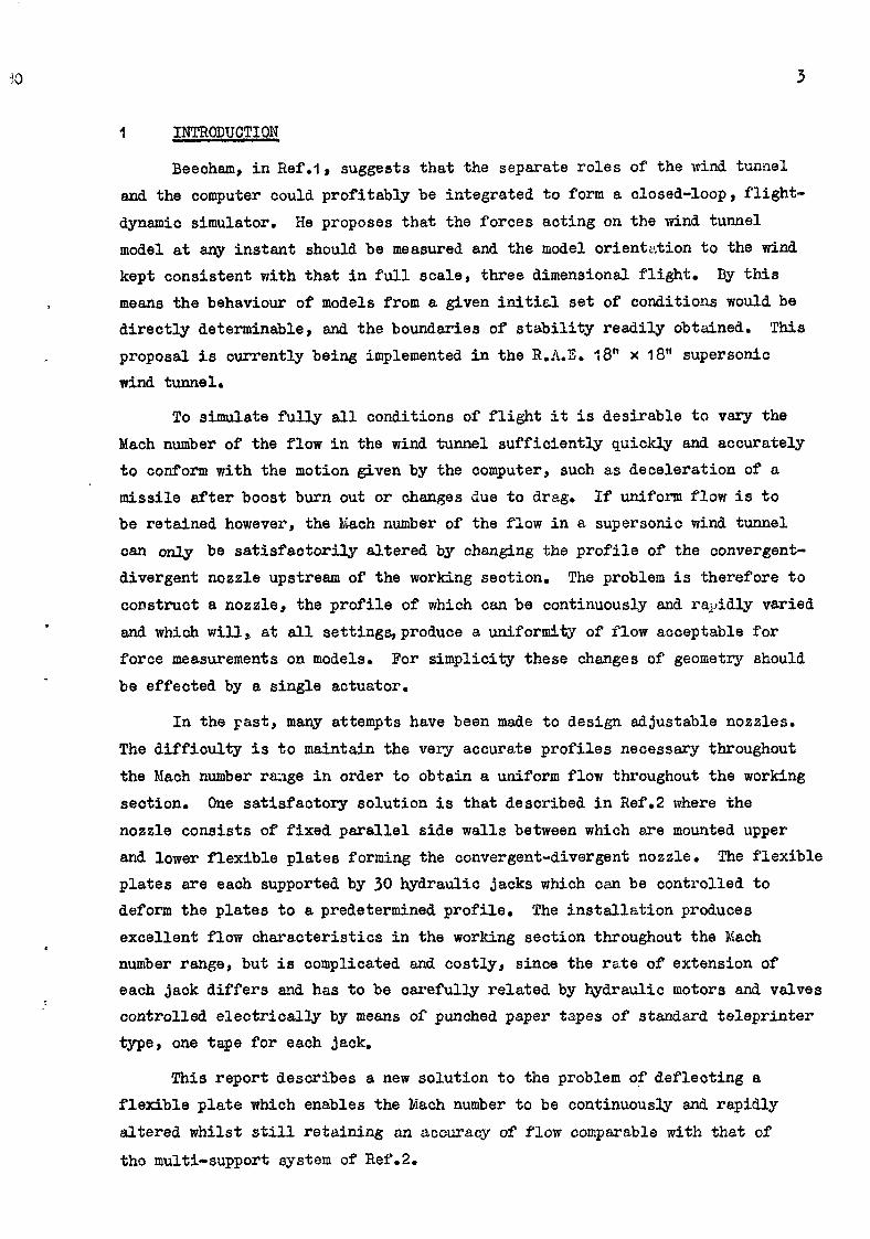
1 INTRODUCTION
Beecham, in Ref.1, suggests that the separate roles of the wind tunnel and the computer could profitably be integrated to form a closed-loop, flight- dynamic simulator. He proposes that the forces acting on the wind tunnel model at any instant should be measured and the model orientation to the wind kept consistent with that in full scale, three dimensional flight. By this means the behaviour of models from a given initial set of conditions would be directly determinable, and the boundaries of stability readily obtained. This proposal is currently being implemented in the R.A.E. 18” x 18” supersonic wind tunnel.
To simulate fully all conditions of flight it is desirable to vary the Mach number of the flow in the wind tunnel sufficiently quickly and acourately to conform with the motion given by the computer, such as deceleration of a missile after boost burn out or changes due to drag. If uniform flow is to be retained however, the Mach number of the flow in a supersonic wind tunnel oan only be satisfaotorily altered by changing the profile of the convergent- divergent nozzle upstream of the working seotion. The problem is therefore to construct a nozzle, the profile of which can be continuously and rapidly varied and which will, at all settings,produce a uniformity of flow acceptable for force measurements on models. For simplicity these changes of geometry should be effected by a single actuator.
In the Fast , many attempts have been made to design adjustable nozzles. The difficulty is to maintain the very accurate profiles necessary throughout the Mach number range in order to obtain a uniform flow throughout the working section. One satisfactory solution is that described in Ref.2 where the nozzle consists of fixed parallel side walls between which are mounted upper and lower flexible plates forming the convergent-divergent nozzle. The flexible plates are each supported by 30 hydraulic jacks which can be controlled to deform the plates to a predetermined profile. The installation produces excellent flow characteristics in the working section throughout the Mach number range, but is oomplicated and costly, since the rate of extension of each jack differs and has to be carefully related by hydraulic motors and valves controlled electrioally by means of punched paper tapes of standard teleprinter type, one tape for each jack.
This report describes a new solution to the problem of deflecting a flexible plate which enables the Mach number to be continuously and rapidly altered whilst still retaining an accuracy of flow comparable with that of
tho multi-support system of Ref.2.

4
2 PRINCIPLJS OF THE SWIi%ING LINK AND PLLr,XIBLR PLYIE
In common with Ref.2 it is assumed that the nozzle will consist of two
thin metal sheets which may be flexed into the required profiles without developing excessive stresses. The hydraulic jacks are however replaced by a number of swinging links of fixed lengths. The principle is shown diagram-
matically in Fig.'i. The flexible plate is connected to a fixed frame by a number of swinging links rAy rB etc. The lengths of the links and positions of the pivot centres are chosen so that as the end of the plate is moved in a streamwise direction the plate flexes into the curves of a family of profiles designed to produce uniform Mach number distributions.
Vvith the simple swinging arm linkage suggested here it is possible to
generate three such prescribed profiles. In principle more profiles could be fitted with more complicated linkages and slides but the mechanical prob- lems to be overcome would be considerably greater.
Referring to Fig.4 it is assumed that the curves marked M = 1.5, I.9 and
2.3 represent profiles which will result in flow at the lower, middle and upper Mach numbers of the range of supersonic flow to be covered. \rith the linkage considered here it is evident that once one point on each of the three profiles has been selected to represent the connecting point of one of the links to the plate, then the rest of the linkage is uniquely determined for given spacing
of the hinges on the flexible plate. >lthOUgh in principle the selection of
these initial three points is apparently arbitrary it is found that mechanical considerations limit the freedom of this choice, since fouling between links,
and excessive link length, have to be avoided.
Once the initial link and its connecting points, to the plate, say A, A,
and 41 of Fig.1, have been chosen then the positions of connecting points
B, B, and B,, for the next link can be obtained by assuming a discrete spacing between plate fixing points. This spacing will depend on allowable deflections of the plate between links due to different pressure on either side of the plate when the wind tunnel is operating. Points B, B, and B,, now specify the length of link rB and the position of the fixed pivot bearing pB.
By continuing this process, a series of links can be determined which
will flex the plate to the correct profiles at the three chosen Mach numbers. AS the change from one chosen profile to another occurs smoothly and concurrently
over the whole plate it is to be hoped that at intermediate positions, the pro- file will be close to the appropriate profile at that Mach number settinq and
the flow characteristics in the working section acceptable.

30 5
For a constant working section size the profiles at the downstream end would of course have to converge to the same straight line parallel to the stream direction. To fulfil this condition would require links of infinite length in the region of the working section. To avoid this difficulty it is
necessary to relax very slightly the restriction on the working section dimen- sions, permitting a small variation with Zach number. Use can be made of the
fact that the rate of growth of the boundary layer increases with Nach number and that in allowing for the displacement thickness the profiles mey thus be sufficiently displaced.
The above principles have been used to design the small scale nozzle described in the remaining paragraphs.
3 1%~ 547” V~Y.Ur";BLE MACH NUI@:..R SUP.:RSONIC \iIM) 'l'UNiV%
One of the unknown factors affecting the acceptibility of the design is the accuracy of the flow at nozzle settings other than at the three design profiles. To obtain this data and to prove the functioning of the multi-link system, a small scale test nozzle was built to replace the working section of the 53' x 5$', No.2 sup ersonic wind tunnel at R.L.Z., Farnborough.
The nozzle profiles used were scaled from those given in Ref.3 for the 8 ft x 8 ft supersonic wind tunnel at Bedford after correcting for differences in boundary layer thickness. Since the ratio of nozzle length to working section height is greater for the Bedford tunnel the height of the scaled working section was reduced to 3 inches. At a later stage in the design it was decided that only one half of the nozzle should be constructed and a reflec- tion plate fitted along the tunnel centre line, consequently the working sec- tion was finally reduced to I$ x 5$‘.
Due to the small scale of the installation, some difficulties were experienced in the design and manufacture which should be less troublesome in a larger installation. The three main problems were :-
(i) Fixing pivot bearings as close as possible to the surface of a
very thin flexible plate without damaging the surface finish or causing appreciable local increases in plate stiffness.
(ii) Sealing the nozzle where the thin plate slides against the side walls.
(iii) Manufacturing the link lengths to the accuracy required in view of the size of the installation.

6
The final design is shown in detail in Fig.2 and a photograph in Fig.3. The range of Mach number covered was I,5 to 2.3 to correspad to that of the
No.19 R.A,E. supersonic wind tunnel in which the full scale nozzle L.q to be installed. The scale model was designed to operate with atmospheric stagnation pressure*
The flexible plate is 22 SVG (0,028 inch) stainless steel sheet to
specification DTD 166, which has a 0.7% proof stress of 4-O tons in -2 . The
thickness of the plate is such that the combined stresses due to bending, -2 pressure and pretensioning do not exceed 22 tons in . The spacing of the
bearing pivot blocks on the plate is designed so that the deflection of the plate between pivots due to the different pressure on either side is less than 0.001 inch.
The nozzle is designed so that the back face of the flexible plate is vented to the lowest pressure generated on the operative face, viz. that in the working section; thus should leakage occur between the plate and the side walls, the flow would be outwards from the nozzle. Since the greatest pressure difference occurs upstream of the throat, reducing to zero in the working
section, the effects of any leakage on the flow uniformity should, in any case, be slight. This arrangement has the further advantage that the deflections due to pressure difference across the plate are reduced in the region close to the working section,
However, to minimise any leakage a flexible moulded rubber strip, Fig.4, is fixed to the edges of the plate to form a seal between the sliding plate and the fixed side walls of the tunnel. The shape of the seal is designed so that
only the 'horns' touch the side walis during assembly. i:ith the air flowing the pressure difference which occurs between the inner and outer faces of the plate, presses the horn tightly into the corner thus forming an airtight seal with no measurable effect on the uniformity of the flow. To reduce friction when operating the strip is lubricated with a smear of silicon grease.
The Mach number is adjusted by a hand wheel on a screwed rod which con- trols the longitudinal position of the plate. On the full scale installation
it is intended that this hand wheel should be replaced by a hydraulic jack. The plate is tensioned by a pneumatic jack attached to a pivot block at the upstream end of the plate, the pressure in the jack being sufficient to return
the plate against the pressure loads, friction in the pivot bearings and fric-
tion between the sealing strip and the sidewalls. The jack is coupled to a reservoir of relatively large volume so that the pressure and therefore tension, is kept approximately constant during the full movement of the plate.

7
At the junction of the flexible plate and the fixed contraction, the
longitudinal movement of the plate is accommodated within a slot formed by a large block and a tapered cover plate supported on distance pieces. Since it was not possible to curve the three profiles into one slot position without sudden changes in curvature, the block containing the slot is itself pivoted,
so that it could adjust itself to conform to the slope of the plate. On assembly, the gap between the pivoted block and a fixed frame was measured at several noezle settings and a cam plate and follower made to fit between them, Fig.5. The follower was attached to the moving part of the nozzle so that as
the plate slides, the pivoted block is forced to the appropriate posi-
tion and supported against the pressure difference on the.faoes of the plate.
4 CALIBK"LTION OF THE NOZZI3
The flow in the nozzle was calibrated at several nozzle settings exten- ding over a Mach number range of from 1.5 to 2.3. heasurements of static pressure from upstream of the throat to the working section were obtained from holes positioned at 0.75 inch intervals along the centre-line of the reflection
plate. The Mach numbers deduced from these measurements end a measurement of the total head upstream are given in Fig.6,
The uniformity of the flow within the working section was examined by means of 5 hole yawmeters of the type described in Ftef.4. Measurements were obtained at positions approximately &, 4 and 2 of the working section height and width at 0.2 inch intervals longitudinally. The variations in lkiach num-
ber, sidewash and downwash for 5 nozzle settings are given in Figs,-/, 8 and 9. The results shown are typical of the results at other nozzle settings and
probe locations.
Schlieren photographs of the flaw in the tunnel are shown in Fig.40. These show a shock wave in the working section originating 0.75 inch from the end of the flexible liner. The shook wave is due to a 0.002 inch deformation of the plate at the last link position. Since the shock wave is almost at the end of the working section , and the reason for its origin is known, rectifica- tion of the error was deferred until after the nozzle was calibrated and the
feasibility of this type of construction assessed.
Fig.7 shows that , except for the higher kiach numbers, the velocity of the flow increases slightly with distance. This is due to the variation of the rate of the growth of the boundary layer on the reflection plate with Each number,
for which the position of the plate could be designed to be correct at one Mach number only.

8
Vhen a complete installation consisting of two flexible plates is con- structed, the fixed reflection plate will not be present and the problem of
the changing boundary layer thickness will not arise. Considering therefore the flow ahead of the shock wave due to the plate kink, and ignoring this steedy rise in Mach number with distance, it can be observed that the local
fluctuations in Mach number are roughly + 0.010 compared to t 0.006 for the
8 ft.x 8 ft Bedford tunnel. Since errors of + 0.003 inch in link length
occurred during manufacture the results are as good as could be expected.
The sidewash variations, Fig,8, are satisfactory and the effects can clearly be seen of the growth of the boundary layer on the sidewalls which cause the port and starboard flows to be turned inwards by roughly 0.1 degree.
The downwash variations, Pig,y, are larger than desirable and are almost cer- tainly due to the errors in link length which occurred during manufacture.
One of the unknown features of the design, and one which required investigating, was the extent to which irregularities in the flow increase when the nozzle profile is set to some position other than at one of the three chosen profiles, It is pleasing to record that for the range of fvIach number covered with this installation, no recognisable increases in fluctuations occur at off-design settings.
The mechanical operation of the variable nozzle proved to be trouble free and the Mach number could be varied over the whole range within seconds. Repeatability of results was excellent, the air jack tensioning system removing
all effects of backlash in the linkages.
5 MANUFACIVRING PROBIXMS
During the manufacture and assembly of the nozzle, trio design features were noted which require consideration for future installations.
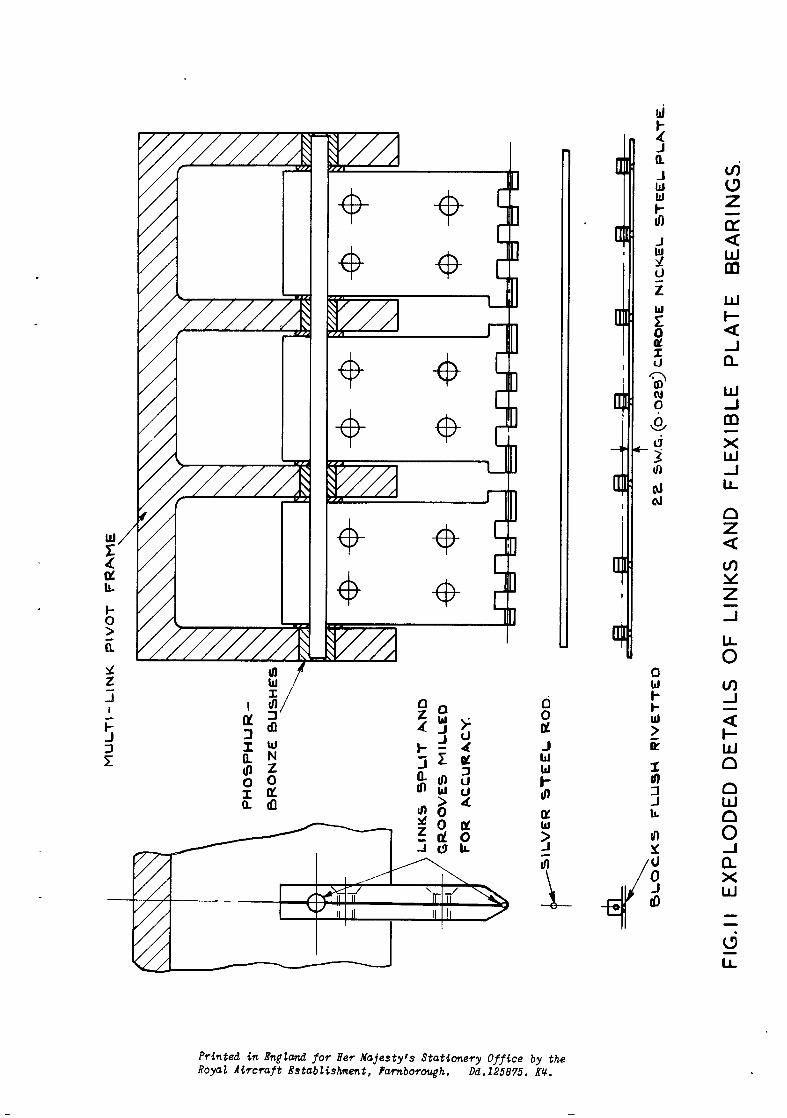
A sketch of the method of construction of the links is shown in Fig,ll. It is seen that three link'plates are used at each station. Each link plate
was origin&Lilly made from a single piece of steel and the bearing holes jig drilled. Because of the length to be drilled, difficulty was experienced in
maintaining parallel holes and eventually the plates were split into two parts, TA
as shomn, and the bearing grooves milled. On assembly it was found that
errors in link length were still present and it is evident that it would have
been preferable to manufacture individual links for each bearing block, the links being jig drilled or made adjustable, set and locked.

9
The centres of the rear row of bearing blocks on the flexible plate Eire positioned considerably higher from the surfaoe then the remainder. Since it is through these bearings that the load is applied to move the plate, an undesirable bending moment is,introduced. Bending is horyever prevented by
arms extending forward to locate on the pivot rod of an upstream row of
bearings. Nevertheless a slight error in assembly has resulted in deformation
of the plate and the formation of a shock in the working section. It is essen-
tial in future installations to ensure that the centres of the bearings are as close as possible to the surface of the plate.
6 CONCLUSIONS
Experiments with a small-scale model of a variable-Mach-number nozzle have been successful. The nozzle, constructed of a flexible plate deformed by
a number of swinging links of varyin, c length attached to a fixed frame, can be
rapidly yet accurately varied to produce flow at any desired Mach number between the design limits. The tests show that a standard of flow throughout the working section similar to that of other variable nozzles with more elaborate mechanisms can be obtained provided the component parts are manufac- tured to the required accuracy.
NOTE : The principle of construction described in this report is the subject of Patent Application No. &g&3/64.

10
No. Author
1 L.J. Beecham W.L. Walters J.W. Partridge
2 T. Barnes C.R, Dunham
3 M.M. Barritt
& D-R, Andrews
W.G. Sawyer
Title, etc.
Proposals fo- p an integrated wind tunnel flight dynamics
simulator system,
A.R.C. 24681, November 1962
Automatic setting of the flexi3le walls of a large
Wiild tunnel,
Proc. Inst, El. Eng. 105 Part A, No.21, June 1958
Calculation of flexible wall shapes and preparation of control tapes for the Bdford 8 ft x 8 ft wind tunnel. A-R-C, R & M No, 3187, February 1959
The calibration of a 60' cone to measure Siach
number, total pressure and flow angles at supersonic
speedso A.R,C. C.P. No* 628 June 1962


POSITION OF GLASS SIDE /WALL ON ASSEMBLY
L---i o* 20”
LEXl8LE STEEL SHEET
MOULDED SEALING STRIP
I (RU88ER 50 SHAW HARDNESS)
FIG. 4 EDGE SEAL FOR FLEXIBLE PLATE

SLOTTED PlVoTiNq t3LOcH
MULTI -LINK FRAME
COVER PLATE SUPPORTEL)
ON DISTANCE PIECES TO FORM
SLOT FOR FLEXIBLE PLATE.
PRESSUR’E:
-uD CAM PLATE ANo i0LLOWER
TO SUPPORT PlVOTEO BLOCK
AT OPTIMUM POSITIONS
- FLOW
FIG ,5 CAM AND FOLLOWER FOR SUPPORTING SLOTTED PIVOTED BLOCK. .

\ I 2-4
2-o
o-e
0*4
0
F1G.6 CENTRE LINE MACH No. DISTRIBUTION FROM STATIC PRESSURE MEASUREMENTS ON REFLECTION PLATE
c /,

x --X PORT SIDE OF TUNNEL. b---Q k OF TUNNEL.
0*95”FROM SURFACE OF
+--0 STAR00ARD SIDE OF TUNNEL. CENTRE-LINE PLATE.
OF SHOCK
I FROM KINK IN
/FLEXlBLL LINER.
FIG.7 DISTRIBUTION OF VELOCITY

X --X PORT SIDE OF TUNNEL, M k OF TUNNEL
0.95” FROM SURFACE OF
O---O STARBOARD StOE OF TUNNfX CENTRE-LINE PLATE.
LOCATION of SHOCK FROM KINK IN
FLEXIBLE LINER. /
FIG 8. DISTRIBUTION OF SIDEWASH

x ---X PORT SIDE OF TUNNEL El- D k OF TUNNEL
O&95” FROM SURFACE OF
o----o STARBOARD SIDE OF TUNNEL CENTRE - LINE. PLATE
I I I L
I LOCATION OF SHOCK FROM UINK IN FLEXIBLE
FIG.9 DISTRIBUTION OF FLOW DOWNWASH

c
Printed in England for Her Majesty’s Stationery Office by the Royal Aircraft Establishment, Farnbol-oqh. Dd.125875. KU.


. ’ Y , .
A.R.C. C.P. NO. 865 Pierce, D. 533.6eOJ.l t
533.6.07l: A SIMPLE FLMIB3.S SJPERSONIC WIND ‘XU?WL NOZZLS POIl THE RAPID AND ACCURATE VARIATION OF FILM MACH NWBER
%3.&O~l.5
533.&07l rl t 533.6.07I I 533.6.011.5
-196 I
Decealber 1965
The &sign of a simple!, variable gec6MJY nozzle for a supersonic wind The design of a siq8le, variable geom?try nozzle for a supersonic wind tunnel is described. The method of construction enables the Mch xnnnber of tumel is described *phc retlxM of caWtxWction enables the Mach number of the flow to be continuously and accurately altered nhile tests are pro- tbc flom to be umthmamly and accurately altered nhile tests are pro- ceeding. Although designed to be incorporated as part of a flight silsula- ceedim Al- de&r&d to be imorparated as part of a flight simula- tor, the installation is suitable for no-1 wind tumel testing especially tar, the installatiem is suitable for nonml wind tunml testing especially where tests at a particular Mach number are essential. * tests at a particular t¶ach nunber an essential.
The results of the calibration of ths flow in a mall scale test section are given. The tests show that it is possible to obtain a standard of flow throughout the working section similar to that obtained with fixed mzzle installations.
the results of tbc call~tion of the flow in a spa11 scale test section are giwm. 3~ tests shnr tlut it is possible to obtain a standard of flow throq@U Um norIcing section similar to that obtainad with fixed nozzle installations,
A.RC* C.P. NQ. a55
53%4071 l 1 I !TJ3.&07l t !S33.bOl1.5
December 1965
The de&n of a sfisile, variable geometry nozzle for a supersonic wind turrl is desixlbed. Rs method of COIIStNCtion enables the Mach mer of tbc fluw to be cumGimcusly and accurately altered while tests an pro- ocedlng Altlmgln designed to be incorporated as part of a flight simula- tor, th? insG&lation is suitable Ior normal wind tunnel testing especially n&we t.eeSes at a ~icular Mach number are essential.
T&E nsllles of tl~ calibration of the flow in a small scale test section are glvea. ‘I’& tests show that it is possible to obtain a standard of flow tiu-a@mt 83~ wa%ing section similar to that obtained with fixed nozzle -tims.


C.P. No. 865
o Crown Copyright 1967
Published by HER MAJESTY’S STATIONERY OFFICE
To be purchased from 49 High Holborn, London w.c.1 423 Oxford Street, London w.1 13~ Castle Street, Edinburgh 2
109 St. Mary Street, Cardiff Brazennose Street, Manchester 2
50 Fairfax Street, Bristol 1 35 Smallbrook. Ringway, Birmingham
80 Chichester Street, Belfast 1 or through any bookseller
5 ,
C.P. No. 865 S-0. CODE No. 23-9016-65