a simulation tool to support signalling and train control ... · a simulation tool to support...
TRANSCRIPT

A simulation tool to support signalling and train control design for high-capacity railways
D. C. Gill & A. Grostate Invensys Rail, Chippenham, UK
Abstract
New-generation signalling and train control systems, such as ETCS-level 2, distance-to-go ATC and many CBTC implementations, effectively transfer responsibility for safe train separations from track-based ‘fixed block’ sections to dynamic on-board calculations using data from speed sensors. Signalled line capacity, in terms of trains per hour, is thereby directly dependent on true train speed, rather than a single worst-case speed curve applied as the basis of previous generation fixed-block designs. The scheme design process therefore widens in scope to permit the optimisation of line capacity by the strategic adjustment of target driving speeds and, where applicable, the optimisation of train-detection equipment in relation to geographical headway criticality. To predict with accuracy the performance supported by a given scheme design, a validated simulation tool is applied that models the movement of trains under both steady-state and perturbed service conditions. The paper describes the development of such a tool and, as a case example, focuses on its application in supporting scheme-design for the re-signalling by Invensys Rail of the London Underground Victoria Line, under a contract with Bombardier Transportation. This replaces a pioneering 1960s fixed-block ATC system with a radio-based ATC system that applies dynamic distance-to-go calculations. Keywords: advanced train control, train simulation, railway signalling, ETCS, CBTC, ATC, DTG-R, ATP, ATO.
1 Introduction
The traditional scope of signalling scheme design includes the safety calculations to evaluate fixed-block section lengths and the allocation of signalling equipment in such a way that permits the level of train service required by the railway
Computers in Railways XIII 99
www.witpress.com, ISSN 1743-3509 (on-line) WIT Transactions on The Built Environment, Vol 127, © 2012 WIT Press
doi:10.2495/CR120091
administration. Where train control systems based on on-board safety calculations are, to a growing extent, replacing conventional fixed-block installations, the scheme design process alters in scope. This is due, fundamentally, to safe train separations being calculated on-board from measured train-speed, rather than, as previous, being calculated ‘off-line’ from a single worst-case speed curve for the rolling stock having the worst braking capability. Scheme design therefore extends the role of the signalling design engineer to consider the control performance of the train as a design parameter in fulfilment of contractual targets for signalled headway and inter-station transit times. It requires the design engineer to be able to quickly assess the impact on headways and transit times of various options for train control and signalling scheme layout. Invensys Rail has therefore developed a multi-train simulation program that provides a design tool for this purpose. This supports scheme-design for contracts, tendering and feasibility assessments for Communication-Based Train Control (CBTC), the European Train Control System (ETCS-level 2) and the Invensys Rail radio-based Distance-to-Go (DTG-R) automatic train control system. The performance principles of the DTG-R system are described in section 2. Section 3 looks at the simulation requirements over a project life cycle. Section 4 describes the primary performance measurements that the simulation tool evaluates. An overview of the tool is presented in section 5 in terms of the constituent models. Section 6 describes the application of the tool to support the re-signalling by Invensys Rail of the London Underground Victoria Line under a contract with Bombardier Transportation, and now in full passenger service.
2 Performance principles of DTG-R automatic train control
2.1 Overview
The DTG-R Automatic Train Control (ATC) system replaces conventional fixed-block track sections with an on-board dynamic calculation of safe braking distance based on measured speed and location. Track-based train detection sections are retained but these are targeted on locations critical to headway and where required to provide route-release at points and crossings. The section lengths are maximised over non-critical areas, thereby reducing track equipment. Unlike fixed-block systems, the provision of safe overlap distances is effectively de-coupled from the block layout and transferred to on-board safety calculations. Each train receives, via radio transmissions, data from a local track-side ‘Block Processor’ that includes the blocks that are clear ahead and the type of run profile to be applied by the Automatic Train Operation (ATO) controller. From this data, and with reference to a geographical ‘map’ (as one design option), the on-board Automatic Train Protection (ATP) controller determines a ‘Limit of Movement Authority’ (LMA). The ATP controller continually re-evaluates the safe braking distance based on measured speed and distance, as derived from a multi-sensor system and as recalibrated every 120 metres (on average) using track-mounted Absolute Position Reference (APR) beacons
100 Computers in Railways XIII
www.witpress.com, ISSN 1743-3509 (on-line) WIT Transactions on The Built Environment, Vol 127, © 2012 WIT Press

(Balises). The ATP controller demands the removal of traction and the application of emergency braking if it determines, at any time, that the train has the potential to exceed either the LMA or the envelope of maximum safe speed (MSS). As expanded by Gill [1], when compared with previous generation speed-coded ATC systems, DTG-R has the following performance benefits:
Permits the minimisation of transit times by effectively de-coupling the ‘civil’ track speeds from the signalling speed codes;
Retains, through fixed-block sections, inherent ‘discipline’ on train spacing, thereby avoiding potential bunching of trains in areas that are not critical to headway
Permits improved recovery from service perturbations by permitting impeded trains to close up over headway-critical platform areas
2.2 DTG-R scheme block-layout principles
The block layout principles embodied in the DTG-R design are illustrated in figure 1 with reference to an inter-station section of the re-signalled London Underground Victoria Line, described later see section 6. This shows the relationship between ATP block sections and train-detection sections, and the allocation of multiple overlaps. Multiple overlaps are concentrated over areas where longer platform dwell times are allocated due to high passenger demand. For a given level of train frequency, this translates into a more onerous target for the signalled ‘platform reoccupation’ time (i.e. signalled headway minus dwell time), and thereby necessitates the highest available resolution of train detection.
Figure 1: Scheme layout example.
In addition, an otherwise single platform berth section is split into several short blocks. For close headway operation, this permits the Movement Authority (MA) issued to a train approaching the platform to firstly step through the
Computers in Railways XIII 101
www.witpress.com, ISSN 1743-3509 (on-line) WIT Transactions on The Built Environment, Vol 127, © 2012 WIT Press
platform blocks and then step through the multiple overlaps. The associated End-of-Authority (EOA) is held at the platform ‘starter’ signal (e.g. Signal A1375 in figure 1) until the next block (Block 1375A) is cleared by the train ahead. This arrangement permits a train to move into the platform unimpeded, such that the specified headway can be sustained for all the possible approach speeds.
2.3 ATP evaluation of safe braking distance
The ATP evaluation of emergency braking distance is based on a ‘safe braking model’ agreed with the railway administration, and assumes all parameters of relevance to be at worst-case tolerance. Examples of these factors are as follows:
1. A ‘fault-condition’ acceleration level that, for example, accounts for a credible failure of the traction load-weigh mechanism;
2. Maximum line voltage, taking account of trains nearby that might be regenerating braking power into the traction supply;
3. Reduced emergency brake efficiency caused by thermal brake fade; 4. Worst-case DTG-R speed and location measuring tolerances.
2.4 Performance-optimised ATO control
To minimise both transit times and platform reoccupation times, the ATO controller determines dynamically how close it can regulate train-speed with sufficient tolerance within the ATP intervention envelope. To achieve this within the requirements for system diversity, it performs an independent evaluation of the safe braking distance, but offsets this by a time margin. Through calculation and scheme simulation verification, this margin is configured to be sufficient for the ATO controller to initiate a smooth transition from the prevailing control state to a service-brake deceleration state without incurring ATP intervention.
3 Scheme simulation requirements
3.1 Demonstration of compliance with client requirements for performance
With safety criticality largely transferred from the scheme block design to the on-board ATP controller, the scheme design process instead takes on a ‘commercial criticality’ in being accurate enough to demonstrate compliance with contractual performance targets. In order to verify at the tendering stage the technical feasibility of meeting the combination of specified reoccupation times and specified transit times, the simulation tool is initially applied in a ‘pure moving block’ mode. This identifies the upper theoretical limit on performance, based solely on the railway infrastructure and the train characteristics.
3.2 Performance verification throughout the project life cycle
Performance simulation has a lifecycle characterised by continuous iteration of a series of phases, which allows increased accuracy of modelling to be achieved as the project continues. Any inaccuracies found during the validation stage may
102 Computers in Railways XIII
www.witpress.com, ISSN 1743-3509 (on-line) WIT Transactions on The Built Environment, Vol 127, © 2012 WIT Press
result in the modification of the tool or input data that is incorrect. Typically, ‘real world’ data is also refined during the project lifecycle, such as measurements of train performance, or adjusted geographical data, reflecting “as-built” status. It is differences such as these that result in the need for re-simulation. This provides increasing accuracy and confidence of the performance output as the project progresses at defined stages in the lifecycle. It also either confirms that the performance is still being achieved or allows action to correct the system if the performance does not match that required.
4 Overview of scheme simulation tool
4.1 Functional requirements
The scheme simulation tool provides a validated model for predicting key performance measures supported by a given signalling scheme design when in conjunction with a given set of ATC configuration and train-performance parameters. The performance is typically measured under ‘full speed’ and ‘at-rest’ conditions. Under ‘full-speed’ conditions a train operates on the limit of being checked by a restrictive Movement Authority. Under ‘at-rest’ conditions, a train is fully impeded and brought to rest at a signal or block marker board. The aim of the latter measure is to assess, for example, how quickly a platform can become reoccupied following an extended dwell suffered by a preceding train The tool is applied by signalling design engineers in assessing the performance supported by a given scheme design and in adjusting that design accordingly. Unlike conventional fixed-block scheme design, the signalled headway is dependent on the true train speed rather than a theoretical worst-case maximum. This feature permits the scheme design to trade small reductions in line speed for significant improvements in headway. For example, a recent feasibility study conducted by Invensys Rail for Crossrail in London [2] indicated that the strategic application of speed reductions at two critical stations would enable three additional trains per hour per direction, while incurring an increase in round-trip journey time of just one percent. On completing a design, the tool produces graphical verification of performance-compliance together with supporting event log files. Configuration control enables particular simulations to be rebuilt at any time in the future.
4.2 Performance measurements
4.2.1 ATO inter-station transit times Where the signalling contractor has responsibility for the supply of train-borne ATO equipment, railway administrations typically specify a set of target inter-station transit times, based on the known upper performance of the rolling stock. This reflects the commercial aim of fully exploiting the capability of new high-performance trains to improve the service and minimise the required fleet size. For a given level of braking capability and given train formation, the laws of physics presents a compromise between minimising inter-station journey times
Computers in Railways XIII 103
www.witpress.com, ISSN 1743-3509 (on-line) WIT Transactions on The Built Environment, Vol 127, © 2012 WIT Press
and maximising train frequency. Put another way, the goal of providing ‘rapid transit’ generally tends to conflict with the goal of providing ‘mass transit’.
4.2.2 Reoccupation times at intermediate platforms The signalled headway for passenger platforms and turn-back locations consists of the dwell duration, the train-door operating time and the signalled reoccupation time. Some recent re-signalling contracts remove the dwell component from the signalling contractor’s scope, as this is instead an issue principally for station design and passenger-flow management. The reoccupation time is dependent on the design of the train (formation, acceleration and deceleration capability), the characteristics of the railway infrastructure (maximum track speed, junction locations and gradient, etc.) and the design of the signalling and train control system. The component due directly to the signalling and train control design is governed by the resolution of train-detection, the delays for equipment processing and data transmission, and the agreed ATP ‘safe braking model’. The calculation of reoccupation time for each platform is performed by the scheme simulation tool automatically by applying a direct-search algorithm that finds the lowest headway for which consecutive train arrivals have an identical speed versus distance profile. A graphical real-time animation enables the design engineer to identify the critical locations and make adjustments accordingly within the constraints of the railway infrastructure.
4.2.3 Reoccupation time interval at turn-back locations The turn-back arrangements at terminal stations often constrain the headway performance of the whole railway. As described more fully by Gill [3], the geometry of the track layout and availability of overrun track are two of the principle factors that limit the frequency with which trains can be turned back. Given the fixed geometry of the track layout and the associated maximum track speeds permitted across junctions, the performance measure of relevance is the minimum reoccupation time at each terminal platform. An example of a terminal station layout that is typical on the London Underground is shown in the lower part of figure 2. This has a scissors crossover at the station throat that enables train arrivals to alternate between the two platforms. The upper part of the diagram shows the ‘headway curves’ (time versus distance graph) for two trains (‘Train 1’ and ‘Train 2’) operating at the lowest platform reoccupation time permitted by the block layout and train control system. The Movement Authority (MA) (dashed line) for Train 2, when approaching either the Platform 1 or 2, cannot be extended beyond the overlap of ‘Signal A’ until the train leaving Platform 1 has cleared the points, and that this condition has been detected and processed by the signalling equipment. Included in this delay is the time required for the points to move and be locked. The simulation tool is configured to calculate the transit time for the two trains between the critical locations. This is repeated for each platform to enable the headway capability to be determined for the site as a whole.
104 Computers in Railways XIII
www.witpress.com, ISSN 1743-3509 (on-line) WIT Transactions on The Built Environment, Vol 127, © 2012 WIT Press
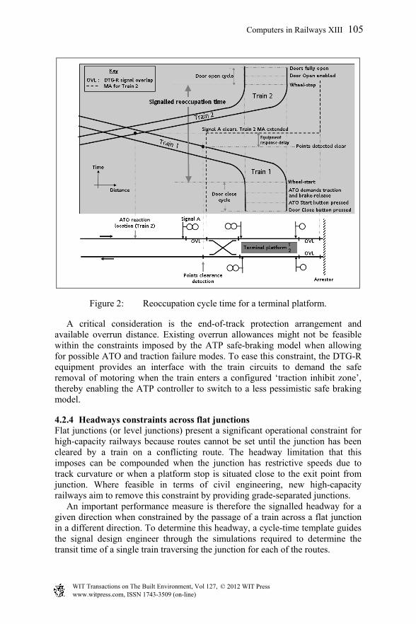
Figure 2: Reoccupation cycle time for a terminal platform.
A critical consideration is the end-of-track protection arrangement and available overrun distance. Existing overrun allowances might not be feasible within the constraints imposed by the ATP safe-braking model when allowing for possible ATO and traction failure modes. To ease this constraint, the DTG-R equipment provides an interface with the train circuits to demand the safe removal of motoring when the train enters a configured ‘traction inhibit zone’, thereby enabling the ATP controller to switch to a less pessimistic safe braking model.
4.2.4 Headways constraints across flat junctions Flat junctions (or level junctions) present a significant operational constraint for high-capacity railways because routes cannot be set until the junction has been cleared by a train on a conflicting route. The headway limitation that this imposes can be compounded when the junction has restrictive speeds due to track curvature or when a platform stop is situated close to the exit point from junction. Where feasible in terms of civil engineering, new high-capacity railways aim to remove this constraint by providing grade-separated junctions. An important performance measure is therefore the signalled headway for a given direction when constrained by the passage of a train across a flat junction in a different direction. To determine this headway, a cycle-time template guides the signal design engineer through the simulations required to determine the transit time of a single train traversing the junction for each of the routes.
Computers in Railways XIII 105
www.witpress.com, ISSN 1743-3509 (on-line) WIT Transactions on The Built Environment, Vol 127, © 2012 WIT Press

4.2.5 Verification of ATO performance Contractual requirements for the determination of performance are in terms of a ‘full-speed’ unimpeded condition at one extreme, and an ‘at-rest’ fully-impeded performance condition at the other. The overall system design must also consider the performance of the signalling and train control system over all headways in between these extremes. This is in order to verify compliance with the following:
ATO speed-control remains stable for all speed transitions, and that its hysteresis control parameters are configured correctly to avoid excessive demand cycles between motoring and service braking;
ATO target points for civil speed restrictions are configured correctly, with adequate tolerance to avoid ATP intervention;
Each DTG-R overlap is sufficient in length to enable the ATO to bring the train to rest correctly at all signal stop locations and block marker boards, with adequate tolerance to avoid ATP intervention.
5 Components of the signalling and train control model
5.1 Train-borne control and protection equipment
The DTG-R train control and protection system model for each simulated train is shown in figure 3 in terms of an overview transfer-function diagram. The train control function consists of three major components; these being the ATO controller, the train traction and service-brake control system, and the train motion dynamics. The model is solved using numerical integration having a time-increment sufficiently small to characterise the changes in state associated with traction jerk-control and the ATO closed-loop control calculations.
Figure 3: Train control and protection model.
106 Computers in Railways XIII
www.witpress.com, ISSN 1743-3509 (on-line) WIT Transactions on The Built Environment, Vol 127, © 2012 WIT Press
5.2 Train motion dynamics
The model of motion dynamics considers all external forces acting on the train due to track gradients, track-curvature, rolling resistance and aerodynamics. The inertia of rotating elements, such as wheel-sets, traction gear-wheels and motor armatures, requires verification from the train builder, as this can increase the effective dynamic mass of a train by as much as 10 percent [4] and thereby impact on the predicted headways through reduced acceleration.
5.3 Traction and service braking control
Modern multiple-unit train designs combine the control of traction and service-braking by controlling the traction motors to deliver either propelling effort or electric braking effort. Due to power limitations at higher speeds, the electric brake effort is dynamically ‘blended’ with pneumatically-controlled friction braking in order to deliver a total braking effort sufficient to meet the ATO demand. Verification is required that the deceleration demanded by the ATO controller is available over the whole speed range. The model also makes provision for the effect on acceleration of section ‘gaps’ in the traction power supply. Transitional time lags are modelled as incurred due to the response of traction and service-brake controller to ATO demand changes. A jerk-limit model is configured with client-specified limits for all changes in acceleration.
5.4 ATO speed control
The ATO model regulates the train speed under closed-loop control from station to station and within the constraints imposed by the MA and envelope of maximum safe track speed. A run profile is selected as, for example, energy-efficient or ‘flat-out’, as specified for the particular performance measurement. ATO service-brake deceleration curves are generated for reductions in safe track speed and when a restrictive MA is encountered. In platform areas, the ATO controller regulates the speed according to how close the train is to the MA. This enables it to optimise the control of speed when operating to close headways whilst not compromising the attainment of contractual performance targets.
5.5 ATP speed and distance monitoring
The ATP (or ETCS European Vital Computer) speed and distance monitoring model continually evaluates the safe braking distance based on measured speed and location. It detects whether the train has the potential to exceed either the MA or the safe track speed. When the ATP model detects such an occurrence, the simulation is aborted because this indicates the need to re-run the simulation using suitably adjusted ATO configuration values.
5.6 Time lags associated with processing a new movement authority
The delay associated with the processing of a new MA adds directly to the signalled platform reoccupation time. In terms of the sensitivity on line capacity,
Computers in Railways XIII 107
www.witpress.com, ISSN 1743-3509 (on-line) WIT Transactions on The Built Environment, Vol 127, © 2012 WIT Press

a reduction in reoccupation time of 4 seconds enables an extra train to be operated in a 30 trains-per-hour service. When applied to a suburban railway such as Thameslink in London this translates into an extra 1800 passenger spaces per hour in each direction [5]. The total MA update delay has a chain of processing elements associated with train-detection, interlocking, automatic route setting, the compilation of ‘state-of-the railway’ data by the Block Processor, and finally the on-board ATP and ATO systems. The scheme design must also consider additional processing delays associated with the transfer of data between adjacent interlocking areas. This is in order to give a local Block Processor ‘visibility’ of block states ahead and thereby prevent a train being impeded due its MA not extending far enough.
6 Application example: the London underground Victoria line upgrade project
The re-signalling for the Victoria Line Upgrade (VLU) replaces pioneering first-generation ATC equipment, supplied to London Transport in the 1960s by Westinghouse Brake and Signal Company (later renamed Invensys Rail) with a new-generation DTG-R based ATC system. This permits an increase in service frequency from 27 trains per hour to a target peak level of 33 trains per hour [6]. Performance-optimised ATO, in conjunction with high-performance regenerative trains supplied by Bombardier Transportation, reduce the journey times by 16 percent [6]. A new Service Control Centre, with an Automatic Train Supervision system supplied by Invensys Rail, implements Automatic Train Regulation (ATR) algorithms to optimise traffic flow by applying low-level adjustments to platform dwell times and selecting different ATO run profiles. For VLU and other re-signalling projects, London Underground in the late 1990s devised a novel metric that specifies railway performance in terms of passenger requirements rather than in terms of train control technology. These requirements are embodied in a London Underground model called the Scheduled Journey Time Capability (SJTC), which incentivises performance improvements and penalises performance shortfalls. As described more fully by Love [7], the SJTC represents a generalised journey time that reflects the combination of service frequency, train passenger capacity and speed. During the early tendering and design stages, Bombardier Transportation and Invensys Rail worked jointly to optimise the technology in terms of train-door layout options, signalled capacity and transit times in order to meet, or improve on, the SJTC target set by London Underground for the Victoria Line Upgrade. The re-signalling was in two phases. The first phase involved the overlay of the new DTG-R system on to the existing 1960s track-code ATC system in order to facilitate the inter-operation of existing ‘1967 Tube Stock’ camshaft trains with the progressive introduction of the new ‘2009 Tube Stock’ high-performance inverter-controlled trains. The second phase, called ‘asset replacement’, involved the reconfiguration of the new signalling to enable a full DTG-R headway capability following the removal of the final 1967 Tube Stock
108 Computers in Railways XIII
www.witpress.com, ISSN 1743-3509 (on-line) WIT Transactions on The Built Environment, Vol 127, © 2012 WIT Press
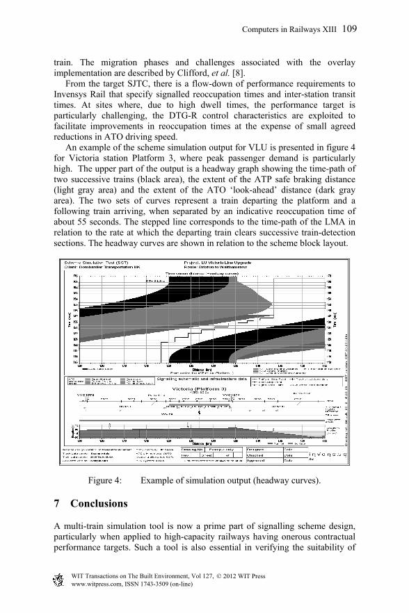
train. The migration phases and challenges associated with the overlay implementation are described by Clifford, et al. [8]. From the target SJTC, there is a flow-down of performance requirements to Invensys Rail that specify signalled reoccupation times and inter-station transit times. At sites where, due to high dwell times, the performance target is particularly challenging, the DTG-R control characteristics are exploited to facilitate improvements in reoccupation times at the expense of small agreed reductions in ATO driving speed. An example of the scheme simulation output for VLU is presented in figure 4 for Victoria station Platform 3, where peak passenger demand is particularly high. The upper part of the output is a headway graph showing the time-path of two successive trains (black area), the extent of the ATP safe braking distance (light gray area) and the extent of the ATO ‘look-ahead’ distance (dark gray area). The two sets of curves represent a train departing the platform and a following train arriving, when separated by an indicative reoccupation time of about 55 seconds. The stepped line corresponds to the time-path of the LMA in relation to the rate at which the departing train clears successive train-detection sections. The headway curves are shown in relation to the scheme block layout.
Figure 4: Example of simulation output (headway curves).
7 Conclusions
A multi-train simulation tool is now a prime part of signalling scheme design, particularly when applied to high-capacity railways having onerous contractual performance targets. Such a tool is also essential in verifying the suitability of
Computers in Railways XIII 109
www.witpress.com, ISSN 1743-3509 (on-line) WIT Transactions on The Built Environment, Vol 127, © 2012 WIT Press

ATO configuration parameters for optimum control over the complete range of operating speeds that potentially occur during service perturbations. In application, the simulation tool described has supported the scheme design phase for the challenging Victoria Line Upgrade project. New high-performance energy-efficient trains now operate under the full protection and control of a new-generation DTG-R automatic train control system. Shorter transit times and higher train frequencies now enable London Underground to meet challenge of responding to the huge increase in passenger demand that has built up over the 40 years since the Victoria Line was opened. Other Invensys Rail projects that the simulation tool has provided scheme-design support include Singapore Downtown Line in implementing SIRIUS CBTC technology (Page [9]), and Network Rail Thameslink in London in developing, as a pioneering project for a mainline railway, ATO control under the protection of ETCS-level 2 [5].
Acknowledgements
The authors wish to thank the Directors of Invensys Rail for giving permission to present this paper at COMPRAIL 2012, and Bombardier Transportation and London Underground for giving approval in relation to the VLU project.
References
[1] Gill, D., Distance-to-Go ATC for mass transit railways: performance and control, Institution of Railway Signal Engineers International Conference ASPECT2006, London, 2006.
[2] Robins, P. and Osgood, J., Signalling choices for Crossrail, Institution of Railway Signal Engineers, IRSE News, Issue 173, pp 2-6, December 2011.
[3] Gill, D.C., Assessment of mass transit turn-back capacity using dynamic simulation models, International Conference on Computers in Railways COMPRAIL2000, Bologna, September 2000.
[4] McGean, T., Urban Transportation Technology, ISBN 0669999113, Lexington Books, DC Heath, 1976.
[5] Bates. P.H. and Weedon, D.N., Thameslink ATO and ETCS: Metro operation of a main-line railway? Institution of Railway Signal Engineers, IRSE News, Issue 170, pp. 2-9, September 2011.
[6] Our upgrade plan, London Underground, publicity brochure, February 2011.
[7] Love, A.G.H., The capabilities of capability – A new approach to procuring railway capacity, Institution of Railway Signal Engineers International Conference ASPECT03, London, 2003.
[8] Cliffort P., Godfrey, T., Heath, A. and Roberts, R., Implementing the Victoria Line overlay signalling system, Institution of Railway Signal Engineers, IRSE News, Issue 142, pp. 8-13, February 2009.
[9] Page, C.R., Signalling Singapore’s Downtown Line, Institution of Railway Signal Engineers International Convention 2011, Singapore, 2011.
110 Computers in Railways XIII
www.witpress.com, ISSN 1743-3509 (on-line) WIT Transactions on The Built Environment, Vol 127, © 2012 WIT Press