a single camera omni stereo vision system for 3d
TRANSCRIPT
A Single−Camera Omni−Stereo Vision System for 3D Perception ofMicro Aerial Vehicles (MAVs)
Carlos Jaramillo, Ling Guo, and Jizhong Xiao∗†∗ Senior Member, IEEE
Abstract— The limited payload and on-board computationconstraints of Micro Aerial Vehicles (MAVs) make sensor con-figuration very challenging for autonomous navigation and 3Dmapping. This paper introduces a catadioptric single-cameraomni-stereo vision system that uses a pair of custom-designedmirrors (in a folded configuration) satisfying the single viewpoint (SVP) property. The system is compact and lightweight,has a wide baseline which allows fast 3D reconstruction basedon stereo calculation. The algorithm for generating rangepanoramas is also introduced. The simulation and experimentalstudy demonstrate that the system provides a good solution tothe perception challenge of MAVs.
I. INTRODUCTION
Micro aerial vehicles (MAVs), such as quadrotor heli-copters, keep emerging as popular platforms for unmannedaerial vehicle (UAV) research due to their structural sim-plicity, small form factor, their vertical take-off and landing(VTOL) capability and high maneuverability. They havemany military and civilian applications, such as target lo-calization and tracking, 3D mapping, terrain and utilitiesinspection, disaster monitoring, environmental surveillance,search and rescue, traffic surveillance, deployment of instru-mentation, and cinematography.
The limited payload and on-board computation constraintsof MAVs make sensor configuration very challenging forautonomous navigation and 3D mapping, which demandcompact and lightweight sensors as well as efficient signalprocessing algorithms suitable for on-line implementation.The most commonly used perception sensors on quadrotorsare laser scanners and cameras (i.e., monocular, stereo, fish-eye, and omni-directional cameras). Recently, red,green,blueplus depth (RGB-D) sensors like the Microsoft Kinect R©,have been adopted for indoor navigation [5]. The lightweightHokuyo R© laser scanner produces accurate distance measure-ments on a 2D plane, but requires the quadrotor to moveup and down in order to generate a 3D map. On the otherhand, RGB-D sensors relieve MAVs from the burden offrequent vertical motion while generating a 3D map, but they
This work is supported in part by U.S. Army Research Office undergrant No. W911NF−09 − 1 − 0565, U.S. National Science Foundationunder grants No. IIS- 0644127
Carlos Jaramillo is with the Dept. of Computer Science, The GraduateCenter, The City University of New York (CUNY), 365 Fifth Avenue, NewYork, NY 10016 (e−mail: [email protected])
Ling Guo is with Nanjing University of Science and Technology, China(e−mail: [email protected])
Jizhong Xiao is with the Electrical Engineering Department, The CityCollege of New York, Convent Ave & 140th Street, New York, NY 10031(corresponding author, [email protected])
suffer from a short range and are only suitable for indoorapplications.
Vision sensor configurations for MAVs are different fromthose used in ground robots and high payload UAVs in thefollowing two aspects:
1) Limitations in the sensors’ size and weight are different.In MAV applications, sensors’ physical dimensions andweight are always a big concern. Due to payloadconstraints, MAVs normally require fewer sensors thatare compactly designed, while larger robots have greaterfreedom of sensor choice.
2) Field-of-view is different. Due to their omnidirectionalmotion model, MAVs require 3D observation of the sur-rounding environment. Conversely, most ground robotsonly care about frontal views.
Hence, an imaging system of lightweight compact structure,large field-of-view, and acceptable resolution is needed forMAV applications.
Omnidirectional catadioptric vision systems provide a pos-sible solution and they have been used in autonomous flyingof large UAVs [11] [10]. Researchers have proposed manydifferent catadioptric configurations with various mirrors[7][1][3][18][12][14][9][19] and a single camera in order toproduce stereo images by sacrificing spatial resolution. In[16], 9 possible folded configurations of the single-cameraomni-stereo imaging system are presented and one of them isrealized here. The catadioptric approach to stereo offers prac-tical advantages for MAVs, such as reduced cost, weight, androbust pixel-disparity correspondences since a single cameradoes not introduce discrepancies between cameras’ intrinsicparameters or synchronization issues. Omni-stereo offers thecapability to recover dense omnidirectional depth maps foroccupancy grids generation and MAV path planning.
In our previous work, we developed a novel catadioptric-stereo rig consisting of a perspective camera coaxially-aligned with two spherical mirrors of distinct radii (ina “folded” configuration) [14]. The spherical mirrors areavailable off-the-shelf but the catadioptric-stereo rig does notsatisfy the single view point (SVP) constraint [15], so it canonly be approximated. We extend our research to design aSVP-compliant folded, catadioptric omni-stereo system withcustom designed hyperbolic mirrors. The system is compactand lightweight, satisfies the SVP property, has a widebaseline that enables fast and accurate 3D reconstruction,and has acceptable resolution for UAV applications.
(a) (b) (c)
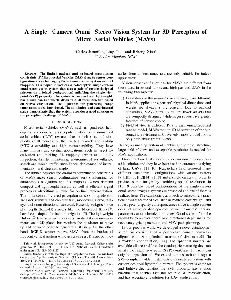
Fig. 1: Synthetic catadioptric single-camera omni-stereo system: a) The simulated rig, consisting of (1) hyperbolical-planarcombined mirror at top, (2) hyperboloidal mirror at bottom, (3) camera (4) transparent cylinder; b) Simulated scenario wherea chess-board, a yellow and a black ball are in the field of view of the omni-stereo vision system; and, c) the image capturedin the scene in Fig. 1b (objects reflected on the bottom mirror appear in the inner image ring, whereas reflections fromthe top mirror are imaged in the outer rings). Note the radial symmetry about the image center. Depth information can becalculated from the corresponding pixel disparities.
II. SENSOR DESIGN
Fig. 1a shows the single-camera catadioptric omni-stereovision system that has been specifically designed for ourquadrotors from Ascending Technologies. It consists of 1)one hyperbolical-planar mirror on the top, 2) one hyper-boloidal mirror on the bottom, and 3) a high-resolutioncamera inside the bottom mirror, all installed inside a 4)transparent acrylic cylinder tube. The choice of the hyper-boloidal shape owes to three reasons: it is one of the fournon-degenerated conic shapes satisfying the SVP constraint[15]; it allows a wider field of view than elliptical and planarmirrors; and it does not require a telescopic (orthographic)lens for imaging as with paraboloid mirrors (so our systemcan be downsized). In addition, the planar part of the uppermirror works as a reflex mirror, so distortion due to the dualreflection is minimal. Based on the SVP property, the systemproduces two radial images for visible objects, one in theinner ring and the other in the outer ring of the image plane(see Fig. 1b and Fig. 1c).
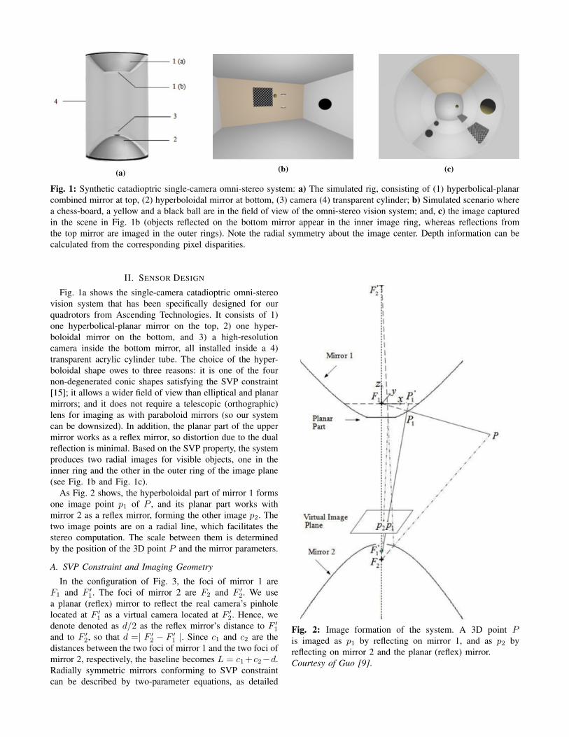
As Fig. 2 shows, the hyperboloidal part of mirror 1 formsone image point p1 of P , and its planar part works withmirror 2 as a reflex mirror, forming the other image p2. Thetwo image points are on a radial line, which facilitates thestereo computation. The scale between them is determinedby the position of the 3D point P and the mirror parameters.
A. SVP Constraint and Imaging Geometry
In the configuration of Fig. 3, the foci of mirror 1 areF1 and F ′1. The foci of mirror 2 are F2 and F ′2. We usea planar (reflex) mirror to reflect the real camera’s pinholelocated at F ′1 as a virtual camera located at F ′2. Hence, wedenote denoted as d/2 as the reflex mirror’s distance to F ′1and to F ′2, so that d =| F ′2 − F ′1 |. Since c1 and c2 are thedistances between the two foci of mirror 1 and the two foci ofmirror 2, respectively, the baseline becomes L = c1 +c2−d.Radially symmetric mirrors conforming to SVP constraintcan be described by two-parameter equations, as detailed
Fig. 2: Image formation of the system. A 3D point Pis imaged as p1 by reflecting on mirror 1, and as p2 byreflecting on mirror 2 and the planar (reflex) mirror.Courtesy of Guo [9].

Fig. 3: Geometric model parameters and field-of-view.Courtesy of Guo [9].
by Baker and Nayar in [15]. Therefore, for the coordinatesystem with origin F1, the respective hyperboloidal parts ofmirror1 and mirror 2 can be represented by:
(Z1 −
c12
)2− (X2
1 + Y 21 )
(k12− 1
)=c214
(k1 − 2
k1
)(1a)(
Z2 −(d− c2
2
))2− (X2
2 + Y 22 )
(k22− 1
)=c224
(k2 − 2
k2
)(1b)
for some point P1 = (X1, Y1, Z1) in mirror 1, andP2 = (X2, Y2, Z2) in mirror 2. k1, k2 ≥ 2 are theeccentricity-related parameters of the corresponding hyper-bolic mirrors.
Different combinations of these parameters affect thesystem dimensions and determine the performance of theimaging system, such as field-of-view, spatial resolution anddepth resolution. Taking mirror 1 as an example, its projec-tive geometry is presented to provide a basic understandingof the imaging process. Let
λ =c1
R1
√k1 · (k1 − 2)− k1Z
(2)
so that point P (X,Y, Z) in homogeneous coordinates withrespect to F1 is reflected at P1 (transformed by λ), andthen imaged as pixel p1 = (u1, v1) through the projection
described by: u1v11
= M2M1
λXλYλZ1
(3)
where R1 =√X2
1 + Y 21 + Z2
1 ,
M1 =
1 0 0 00 1 0 00 0 1 c1
, and M2 =
fu s u00 fv v00 0 1
c1+λZ
In this transformation chain, M1 brings P1 to the coordi-
nate system of F ′1 (or the camera’s frame), and M2 is theintrinsic matrix of the pinhole camera model with pixel focallengths fu & fv , skew term s, and scale factor 1/(c1 + λZ).
B. Vertical Field-of-View (vFOV) ConstraintThe horizontal FOV is 360◦. However, the vertical FOVs
(vFOV) of the two mirrors are different. The bottom mirrorhas a larger vFOV than the upper mirror as shown in Fig.3. The overlapping area of the two mirrors’ vFOVs is thearea where objects can be shown in both inner and outerring images, where the stereo calculation can be performed.In the design, the vFOVs are decided by three angles: α, β,and γ, such that:
vFOV =
{α+ 90− β β < γα+ γ β > γ
(4)
To be installed along the central axis of the quadrotor,the vision system should ensure that objects located 25cmabove (or under) and at 1 meter away from the axis can beviewed. At the same time, angle β should be large enoughto avoid the MAV’s blades from getting imaged. The size ofinner and outer ring images should be in good proportion,as well. Considering all these design factors, we selectα ≥ 14o, β ≥ 65o, γ ≤ 14o . Geometrical relations betweenthese constraints and system parameters can be establishedfrom Fig. 3.
C. Spatial ResolutionThe images acquired by our system are not resolution
invariant. Indeed, an omni-camera producing resolution-invariant images has a non-analytical form of the mirror [6],and therefore, it is not suitable for fast 3D depth calculation.The spatial resolution is defined as the number of pixelsper solid angle. From [15], the relationship between theresolution of upper mirror ηm1 and that of the conventionalcamera ηcam is:
ηm1 = g · ηcam =R2
1
(c1 − Z1)2
+X21 + Y 2
1
ηcam (5)
for a point P1 = (X1, Y1, Z1) in mirror 1 with F1 asthe coordinate frame, where R1 =
√X2
1 + Y 21 + Z2
1 . SinceP1 = λP , we can substitute R1 = λR in g for equation (5),to obtain:
g = (λR)2
(c1−λZ)2+(λX)2+(λY )2
= R2
( c1λ −Z)2+X2+Y 2
(6)
which indicates how the resolution ηcam of a point P inthe image decreases with λ2, and (2) implies it is inverselyproportional with the parameter k1. We observe that thesmaller k1 gets, the flatter the mirror becomes, so it providesa better spatial resolution. However, a smaller k1 requires alarger radius, w of the system in order to achieve a similarvFOV. According to our application, if k1 < 3, it becomesimpractical. On the other hand, the larger k1 gets, the shorterthe baseline L of the stereo system becomes. The sameanalysis is true for mirror 2.
D. Depth Resolution
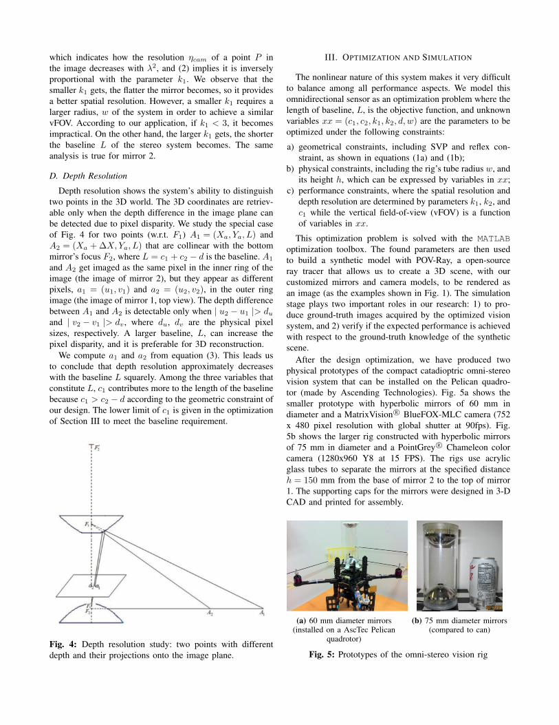
Depth resolution shows the system’s ability to distinguishtwo points in the 3D world. The 3D coordinates are retriev-able only when the depth difference in the image plane canbe detected due to pixel disparity. We study the special caseof Fig. 4 for two points (w.r.t. F1) A1 = (Xa, Ya, L) andA2 = (Xa + ∆X,Ya, L) that are collinear with the bottommirror’s focus F2, where L = c1 + c2 − d is the baseline. A1
and A2 get imaged as the same pixel in the inner ring of theimage (the image of mirror 2), but they appear as differentpixels, a1 = (u1, v1) and a2 = (u2, v2), in the outer ringimage (the image of mirror 1, top view). The depth differencebetween A1 and A2 is detectable only when | u2 − u1 |> duand | v2 − v1 |> dv , where du, dv are the physical pixelsizes, respectively. A larger baseline, L, can increase thepixel disparity, and it is preferable for 3D reconstruction.
We compute a1 and a2 from equation (3). This leads usto conclude that depth resolution approximately decreaseswith the baseline L squarely. Among the three variables thatconstitute L, c1 contributes more to the length of the baselinebecause c1 > c2 − d according to the geometric constraint ofour design. The lower limit of c1 is given in the optimizationof Section III to meet the baseline requirement.
Fig. 4: Depth resolution study: two points with differentdepth and their projections onto the image plane.
III. OPTIMIZATION AND SIMULATION
The nonlinear nature of this system makes it very difficultto balance among all performance aspects. We model thisomnidirectional sensor as an optimization problem where thelength of baseline, L, is the objective function, and unknownvariables xx = (c1, c2, k1, k2, d, w) are the parameters to beoptimized under the following constraints:
a) geometrical constraints, including SVP and reflex con-straint, as shown in equations (1a) and (1b);
b) physical constraints, including the rig’s tube radius w, andits height h, which can be expressed by variables in xx;
c) performance constraints, where the spatial resolution anddepth resolution are determined by parameters k1, k2, andc1 while the vertical field-of-view (vFOV) is a functionof variables in xx.
This optimization problem is solved with the MATLABoptimization toolbox. The found parameters are then usedto build a synthetic model with POV-Ray, a open-sourceray tracer that allows us to create a 3D scene, with ourcustomized mirrors and camera models, to be rendered asan image (as the examples shown in Fig. 1). The simulationstage plays two important roles in our research: 1) to pro-duce ground-truth images acquired by the optimized visionsystem, and 2) verify if the expected performance is achievedwith respect to the ground-truth knowledge of the syntheticscene.
After the design optimization, we have produced twophysical prototypes of the compact catadioptric omni-stereovision system that can be installed on the Pelican quadro-tor (made by Ascending Technologies). Fig. 5a shows thesmaller prototype with hyperbolic mirrors of 60 mm indiameter and a MatrixVision R© BlueFOX-MLC camera (752x 480 pixel resolution with global shutter at 90fps). Fig.5b shows the larger rig constructed with hyperbolic mirrorsof 75 mm in diameter and a PointGrey R© Chameleon colorcamera (1280x960 Y8 at 15 FPS). The rigs use acrylicglass tubes to separate the mirrors at the specified distanceh = 150 mm from the base of mirror 2 to the top of mirror1. The supporting caps for the mirrors were designed in 3-DCAD and printed for assembly.
(a) 60 mm diameter mirrors(installed on a AscTec Pelican
quadrotor)
(b) 75 mm diameter mirrors(compared to can)
Fig. 5: Prototypes of the omni-stereo vision rig
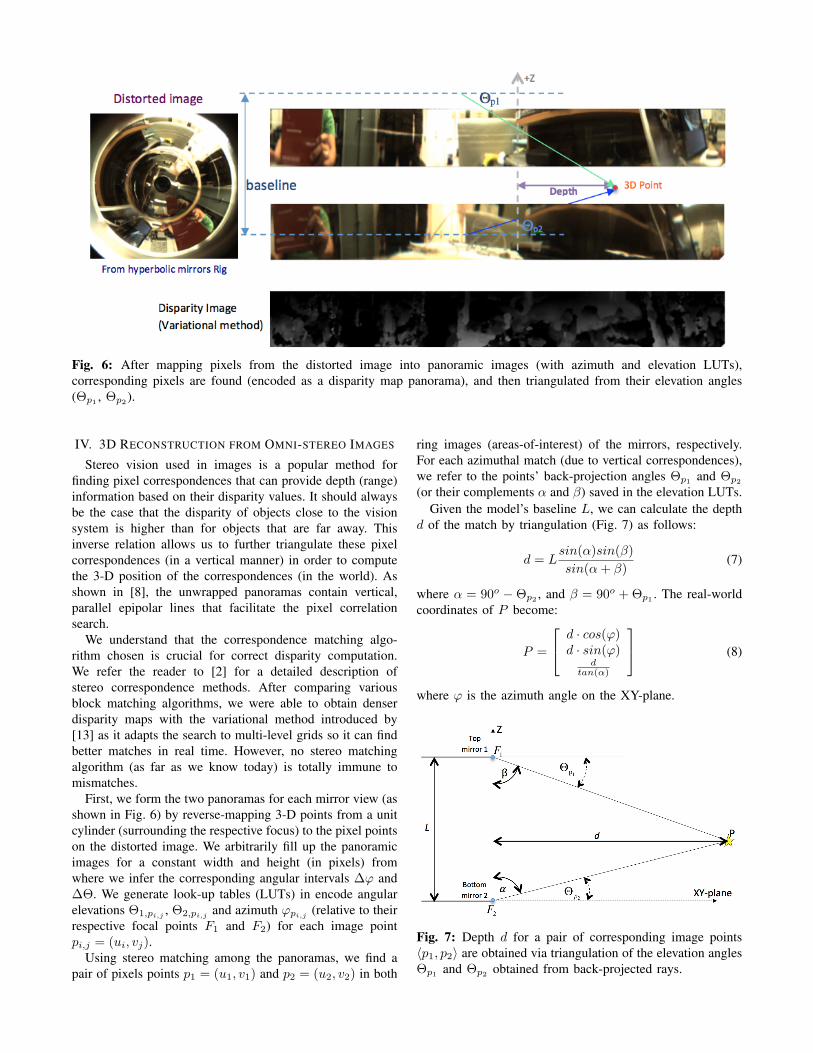
Fig. 6: After mapping pixels from the distorted image into panoramic images (with azimuth and elevation LUTs),corresponding pixels are found (encoded as a disparity map panorama), and then triangulated from their elevation angles(Θp1 , Θp2 ).
IV. 3D RECONSTRUCTION FROM OMNI-STEREO IMAGES
Stereo vision used in images is a popular method forfinding pixel correspondences that can provide depth (range)information based on their disparity values. It should alwaysbe the case that the disparity of objects close to the visionsystem is higher than for objects that are far away. Thisinverse relation allows us to further triangulate these pixelcorrespondences (in a vertical manner) in order to computethe 3-D position of the correspondences (in the world). Asshown in [8], the unwrapped panoramas contain vertical,parallel epipolar lines that facilitate the pixel correlationsearch.
We understand that the correspondence matching algo-rithm chosen is crucial for correct disparity computation.We refer the reader to [2] for a detailed description ofstereo correspondence methods. After comparing variousblock matching algorithms, we were able to obtain denserdisparity maps with the variational method introduced by[13] as it adapts the search to multi-level grids so it can findbetter matches in real time. However, no stereo matchingalgorithm (as far as we know today) is totally immune tomismatches.
First, we form the two panoramas for each mirror view (asshown in Fig. 6) by reverse-mapping 3-D points from a unitcylinder (surrounding the respective focus) to the pixel pointson the distorted image. We arbitrarily fill up the panoramicimages for a constant width and height (in pixels) fromwhere we infer the corresponding angular intervals ∆ϕ and∆Θ. We generate look-up tables (LUTs) in encode angularelevations Θ1,pi,j , Θ2,pi,j and azimuth ϕpi,j (relative to theirrespective focal points F1 and F2) for each image pointpi,j = (ui, vj).
Using stereo matching among the panoramas, we find apair of pixels points p1 = (u1, v1) and p2 = (u2, v2) in both
ring images (areas-of-interest) of the mirrors, respectively.For each azimuthal match (due to vertical correspondences),we refer to the points’ back-projection angles Θp1 and Θp2
(or their complements α and β) saved in the elevation LUTs.Given the model’s baseline L, we can calculate the depth
d of the match by triangulation (Fig. 7) as follows:
d = Lsin(α)sin(β)
sin(α+ β)(7)
where α = 90o −Θp2 , and β = 90o + Θp1 . The real-worldcoordinates of P become:
P =
d · cos(ϕ)d · sin(ϕ)
dtan(α)
(8)
where ϕ is the azimuth angle on the XY-plane.
Fig. 7: Depth d for a pair of corresponding image points〈p1, p2〉 are obtained via triangulation of the elevation anglesΘp1 and Θp2 obtained from back-projected rays.
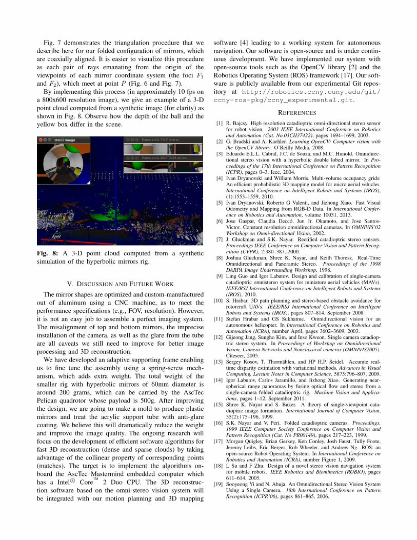
Fig. 7 demonstrates the triangulation procedure that wedescribe here for our folded configuration of mirrors, whichare coaxially aligned. It is easier to visualize this procedureas each pair of rays emanating from the origin of theviewpoints of each mirror coordinate system (the foci F1
and F2), which meet at point P (Fig. 6 and Fig. 7).By implementing this process (in approximately 10 fps on
a 800x600 resolution image), we give an example of a 3-Dpoint cloud computed from a synthetic image (for clarity) asshown in Fig. 8. Observe how the depth of the ball and theyellow box differ in the scene.
Fig. 8: A 3-D point cloud computed from a syntheticsimulation of the hyperbolic mirrors rig.
V. DISCUSSION AND FUTURE WORK
The mirror shapes are optimized and custom-manufacturedout of aluminum using a CNC machine, as to meet theperformance specifications (e.g., FOV, resolution). However,it is not an easy job to assemble a perfect imaging system.The misalignment of top and bottom mirrors, the impreciseinstallation of the camera, as well as the glare from the tubeare all caveats we still need to improve for better imageprocessing and 3D reconstruction.
We have developed an adaptive supporting frame enablingus to fine tune the assembly using a spring-screw mech-anism, which adds extra weight. The total weight of thesmaller rig with hyperbolic mirrors of 60mm diameter isaround 200 grams, which can be carried by the AscTecPelican quadrotor whose payload is 500g. After improvingthe design, we are going to make a mold to produce plasticmirrors and treat the acrylic support tube with anti-glarecoating. We believe this will dramatically reduce the weightand improve the image quality. The ongoing research willfocus on the development of efficient software algorithms forfast 3D reconstruction (dense and sparse clouds) by takingadvantage of the collinear property of corresponding points(matches). The target is to implement the algorithms on-board the AscTec Mastermind embedded computer whichhas a Intel R© Core
TM2 Duo CPU. The 3D reconstruc-
tion software based on the omni-stereo vision system willbe integrated with our motion planning and 3D mapping
software [4] leading to a working system for autonomousnavigation. Our software is open-source and is under contin-uous development. We have implemented our system withopen-source tools such as the OpenCV library [2] and theRobotics Operating System (ROS) framework [17]. Our soft-ware is publicly available from our experimental Git repos-itory at http://robotics.ccny.cuny.edu/git/ccny-ros-pkg/ccny_experimental.git.
REFERENCES
[1] R. Bajcsy. High resolution catadioptric omni-directional stereo sensorfor robot vision. 2003 IEEE International Conference on Roboticsand Automation (Cat. No.03CH37422), pages 1694–1699, 2003.
[2] G. Bradski and A. Kaehler. Learning OpenCV: Computer vision withthe OpenCV library. O’Reilly Media, 2008.
[3] Eduardo E.L.L. Cabral, J.C. de Souza, and M.C. Hunold. Omnidirec-tional stereo vision with a hyperbolic double lobed mirror. In Pro-ceedings of the 17th International Conference on Pattern Recognition(ICPR), pages 0–3. Ieee, 2004.
[4] Ivan Dryanovski and William Morris. Multi-volume occupancy grids:An efficient probabilistic 3D mapping model for micro aerial vehicles.International Conference on Intelligent Robots and Systems (IROS),(1):1553–1559, 2010.
[5] Ivan Dryanovski, Roberto G Valenti, and Jizhong Xiao. Fast VisualOdometry and Mapping from RGB-D Data. In International Confer-ence on Robotics and Automation, volume 10031, 2013.
[6] Jose Gaspar, Claudia Decco, Jun Jr. Okamoto, and Jose Santos-Victor. Constant resolution omnidirectional cameras. In OMNIVIS’02Workshop on Omni-directional Vision, 2002.
[7] J. Gluckman and S.K. Nayar. Rectified catadioptric stereo sensors.Proceedings IEEE Conference on Computer Vision and Pattern Recog-nition (CVPR), 2:380–387, 2000.
[8] Joshua Gluckman, Shree K. Nayar, and Keith Thoresz. Real-TimeOmnidirectional and Panoramic Stereo. Proceedings of the 1998DARPA Image Understanding Workshop, 1998.
[9] Ling Guo and Igor Labutov. Design and calibration of single-cameracatadioptric omnistereo system for miniature aerial vehicles (MAVs).IEEE/RSJ International Conference on Intelligent Robots and Systems(IROS), 2010.
[10] S. Hrabar. 3D path planning and stereo-based obstacle avoidance forrotorcraft UAVs. IEEE/RSJ International Conference on IntelligentRobots and Systems (IROS), pages 807–814, September 2008.
[11] Stefan Hrabar and GS Sukhatme. Omnidirectional vision for anautonomous helicopter. In International Conference on Robotics andAutomation (ICRA), number April, pages 3602–3609, 2003.
[12] Gijeong Jang, Sungho Kim, and Inso Kweon. Single camera catadiop-tric stereo system. In Proceedings of Workshop on OmnidirectionalVision, Camera Networks and Nonclassical cameras (OMNIVIS2005).Citeseer, 2005.
[13] Sergey Kosov, T. Thormahlen, and HP H.P. Seidel. Accurate real-time disparity estimation with variational methods. Advances in VisualComputing, Lecture Notes in Computer Science, 5875:796–807, 2009.
[14] Igor Labutov, Carlos Jaramillo, and Jizhong Xiao. Generating near-spherical range panoramas by fusing optical flow and stereo from asingle-camera folded catadioptric rig. Machine Vision and Applica-tions, pages 1–12, September 2011.
[15] Shree K. Nayar and S. Baker. A theory of single-viewpoint cata-dioptric image formation. International Journal of Computer Vision,35(2):175–196, 1999.
[16] S.K. Nayar and V. Peri. Folded catadioptric cameras. Proceedings.1999 IEEE Computer Society Conference on Computer Vision andPattern Recognition (Cat. No PR00149), pages 217–223, 1999.
[17] Morgan Quigley, Brian Gerkey, Ken Conley, Josh Faust, Tully Foote,Jeremy Leibs, Eric Berger, Rob Wheeler, and Andrew Ng. ROS: anopen-source Robot Operating System. In International Conference onRobotics and Automation (ICRA), number Figure 1, 2009.
[18] L Su and F Zhu. Design of a novel stereo vision navigation systemfor mobile robots. IEEE Robotics and Biomimetics (ROBIO), pages611–614, 2005.
[19] Sooyeong Yi and N. Ahuja. An Omnidirectional Stereo Vision SystemUsing a Single Camera. 18th International Conference on PatternRecognition (ICPR’06), pages 861–865, 2006.