a six sigma approach to implementing conformal cooling on
TRANSCRIPT

Southern Illinois University CarbondaleOpenSIUC
Theses Theses and Dissertations
8-1-2017
A Six Sigma Approach to Implementing ConformalCooling on Existing Processes in Injection MoldingWilliam Josiah JackSouthern Illinois University Carbondale, [email protected]
Follow this and additional works at: http://opensiuc.lib.siu.edu/theses
This Open Access Thesis is brought to you for free and open access by the Theses and Dissertations at OpenSIUC. It has been accepted for inclusion inTheses by an authorized administrator of OpenSIUC. For more information, please contact [email protected].
Recommended CitationJack, William Josiah, "A Six Sigma Approach to Implementing Conformal Cooling on Existing Processes in Injection Molding" (2017).Theses. 2214.http://opensiuc.lib.siu.edu/theses/2214

A SIX SIGMA APPROACH TO IMPLEMENTING CONFORMAL COOLING ON EXISTING
PROCESSES IN INJECTION MOLDING
By
William Josiah Jack
B.S., Southern Illinois University Carbondale, 2013
A Thesis
Submitted in Partial Fulfillment of the Requirements for the
Master of Science in Quality Engineering and Management
Department of Technology
in the Graduate School of
Southern Illinois University Carbondale
May 2017

THESIS APPROVAL
A SIX SIGMA APPROACH TO IMPLEMENTING CONFORMAL COOLING ON EXISTING
PROCESSES IN INJECTION MOLDING
By
William Josiah Jack
A Thesis Submitted in Partial
Fulfillment of the Requirements
for the Degree of Master of Science
in the field of Quality Engineering and Management
Approved by:
Dr. Julie K. Dunston, Chair
Dr. Roger F. Chang
Dr. Tomas Velasco
Graduate School
Southern Illinois University Carbondale
April 4, 2017

i
Abstract
AN ABSTRACT OF THE THESIS OF
William Josiah Jack, for the Master of Science degree in Quality Engineering and Management,
presented on April 4, 2017, at Southern Illinois University Carbondale.
TITLE: A SIX SIGMA APPROACH TO IMPLEMENTING CONFORMAL COOLING ON EXISTING
PROCESSES IN INJECTION MOLDING
MAJOR PROFESSOR: Dr. Julie K. Dunston
Injection molding is one of the most common methods of mass production. After
injecting molten plastic into a mold, the heat must leave the plastic material, enter the mold
steel, enter the coolant, and exit the mold. This heat flow is critical to producing high quality
parts rapidly.
As plastic cools, the plastic shrinks. Uneven cooling causes uneven shrinkage which can
cause the part to warp from the resulting internal stresses or create sink marks on the part.
Thus the effect of uneven cooling is lower part quality, both in appearance and in dimension.
Standard or conventional cooling channels are straight-drilled holes arranged such that
they intersect and connect to form a loop for coolant, typically water, to flow through. This
allows the mold to act as a heat exchanger, transferring heat to the coolant and carrying heated
coolant away from the mold. While standard cooling channels have been used widely in the
injection molding industry for their manufacturability and proven results, other methods have
been developed for creating molds with cooling channels of any desired path or shape. These
channels, called conformal due to how they conform to the shape of the part, provide uniform

ii
cooling, eliminate or reduce the quality issues of warpage and shrinkage, and provide faster,
more economical cycle times. Conformal cooling cannot be produced only by subtractive
manufacturing methods that remove material from raw stock but rather through additive or
hybrid manufacturing techniques that add material in layers of powder, sections, or sheets.
Bonded sheet layer mold inserts can be made of any size and are currently the only feasible
way of making large, conformally-cooled molds. Presented is a Six Sigma approach for
implementing conformal cooling in existing molds to achieve the benefits of higher part quality
and fast cycle times. Feasibility considerations include existing mold features such as slides and
ejectors, choice of channel diameter, and the cooling channel path. Cost justification
considerations include assessing part quality cost impact through calculation of the costs of
poor quality and assessing machine capacity as relates to cycle time. With the approach
presented, an injection molding company should be able to assess feasibility and cost
effectiveness of implementing conformal cooling on its molds.

iii
TABLE OF CONTENTS
CHAPTER PAGE
ABSTRACT .......................................................................................................................................... i
LIST OF TABLES ................................................................................................................................ iv
LIST OF FIGURES ............................................................................................................................... v
CHAPTERS
CHAPTER 1 – Introduction ........................................................................................................... 1
CHAPTER 2 – Related Work ......................................................................................................... 5
CHAPTER 3 – Method ................................................................................................................ 25
CHAPTER 4 – Conclusions .......................................................................................................... 55
CHAPTER 5 – Future Work ......................................................................................................... 57
REFERENCES .................................................................................................................................. 60
APPENDICES .................................................................................................................................. 69
Appendix A – Glossary of Terms and Abbreviations ................................................................. 70
Appendix B – Conformal Cooling Research Timeline ................................................................ 72
Appendix C – Turbulent Flow of Other Cross-Sections ............................................................. 79
VITA ............................................................................................................................................... 82

iv
LIST OF TABLES
TABLE PAGE
Table 1 ............................................................................................................................... 12
Table 2 ............................................................................................................................... 16
Table 3 ............................................................................................................................... 19
Table 4 ............................................................................................................................... 35
Table 5 ............................................................................................................................... 36
Table 6 ............................................................................................................................... 37

v
LIST OF FIGURES
FIGURE PAGE
Figure 1. Conventional Cooling Versus Conformal Cooling ............................................... 5
Figure 2. Methods of Producing Conformal Cooling ......................................................... 9
Figure 3. Cooling Channel Design Guidelines .................................................................. 15
Figure 4. Simple Series and Parallel Mold Cooling Circuits .............................................. 18
Figure 5. Core Cooling Methods. ..................................................................................... 23
Figure 6. Example Cooling Analysis .................................................................................. 39
Figure 7 Cooling System Design Comparison – Fully Versus Partial ................................ 43
Figure 8. Implementation ROI Analysis ............................................................................ 45
Figure 9. Conformal Cooling Break Even Analysis for New Mold .................................... 46
Figure 10. Example Line Capacity Savings........................................................................ 49
Figure 11. SPC Example Chart .......................................................................................... 53

CHAPTER 1
INTRODUCTION
1.1 Overview
In injection molding, exceptional part quality has come to be expected. Modern
equipment is capable of achieving very consistent processes which is expected to create very
consistent, identical parts cycle after cycle. However, mold design plays a key role in achieving
high quality parts. In the injection molding cycle, cooling time accounts for the majority of the
cycle. After melted polymer is injected into the mold, it must cool enough that it can be ejected
without damaging the part or affecting the part dimensions. Using standard cooling methods
such as straight-drilled cooling channels is not the ideal solution and leads to uneven cooling
and creates hot spots in the part. As plastic cools the plastic shrinks. These hot spots, which
may only cover a small area of the part, will cool at a slower rate and experience shrinkage
more slowly than other areas. This can cause warpage in the part structure or sink marks on
the part surface above the hot spots since these areas will continue to shrink after the areas
around them have cooled enough to solidify. Also, these hot spots account for the largest
amount of the cooling time requirement, lengthening the required cycle time. Since the largest
contributing factor to cycle time is cooling, reducing the cooling becomes the critical problem
to solve for achieving a competitive cycle time. A major solution to these problems is to
eliminate hot spots by designing cooling channels into the mold that conform to the shape of
the part to provide optimized and even cooling.

2
However, conformal cooling is not without challenge. The channels require special
manufacturing methods. Creating the complex curved shapes is impossible by normal
machining methods and thus requires additive manufacturing to create. Also, careful
consideration must be taken of factors such as tool strength, tool life, coolant channel cross-
section, coolant channel size and spacing, and coolant channel route design. While most of
these problems are less difficult when first designing a new mold, they can be much more
difficult and come with greater risk when seeking to improve current production molds. Past
studies have thus focused primarily on designing molds with conformal cooling before creation.
This paper presents an approach to cost justify, design, and implement conformal cooling to
improve existing injection molds by following the Six Sigma improvement methodology of
DMAIC – Design, Measure, Analyze, Improve, and Control. The goals of this approach are to
achieve better part quality, more statistically repeatable dimensions, and faster, more
competitive cycle times, while minimizing the risk associated with modifying mass production
tooling. These goals are useful for companies who are seeking to save costs and improve
quality in an increasingly competitive global market. This approach should be practical to apply
for improving current tooling in any injection molding company.
1.2 Injection Molding Cycle
Cooling has always been an important factor in injection molding that affects part
quality and process efficiency by having a direct effect on cycle time since the molten plastic
requires time to cool. The injection molding cycle consists of the following steps: filling, packing
and holding, cooling, mold opening, part ejection and removal, and mold closing.

3
• Filling: Molten plastic is quickly injected into the hollowed-out part cavity inside the mold
to fill 95-98% of the part cavity. As soon as molten plastic touches the mold walls during
filling, the plastic begins to cool forming a “skin” at the interface between the cooler mold
wall and the molten plastic. Thus it is difficult to eliminate the coupling between filling and
cooling stages (Xu 1999).
• Packing and Holding: During packing, plastic is slowly injected to fill the remaining 2-5% of
the part cavity and compensate for shrinkage during the initial cooling. After the cavity is
full, the plastic is then subjected to pressure for a set time. This pressure, called holding,
aids in providing uniform material density in the part and holds the plastic against the mold
walls to better recreate the mold surface in the part which is especially important for
textured mold surfaces. While under pressure, the part begins to cool significantly, from
the outside then inwards. The machine settings must keep the plastic held under pressure
for a long enough time to cool and solidify the gate –the orifice where melted plastic flows
into the part cavity – in order to prevent the still molten innermost plastic from flowing out
of the cavity back through the gate. This is called achieving gate seal.
• Cooling: The molten polymer is allowed to cool in the closed mold for a set time until the
part reaches the ejection temperature where it is cool enough to be safely ejected without
affecting part quality. The cooling stage typically accounts for the largest portion of the
overall cycle time. During cooling, the plastic begins to shrink. The mold is designed to be
slightly larger to compensate.
• Mold Opening: Once the set cooling time is past, the mold will be opened.

4
• Part Ejection and Removal: The parts are designed to shrink onto and thereby adhere to
one side of the mold which contains an ejection system. The ejection system, typically a
series of pins attached to one plate, will move uniformly to push the parts off the mold with
even pressure. At this point the parts can either fall into a tote below or be taken by a
robot for more careful handling.
• Mold Closing: The mold then closes, readying the process to begin again.
If the parts are not cooled enough, there can be poor part quality such as ejector pins
leaving undesirable indents or the part could warp as the plastic continues to shrink in areas
that are still hot while areas that are cooled have stopped shrinking. With even less cooling,
the ejectors may push through the molten material, leaving the part adhered to the mold.
In many cases there is a compromise between exceptional quality and a fast cycle. This
is because a large portion of the cooling time is taken to cool particular portions of a part,
notably thick sections or sections furthest from the flowing coolant in the cooling channels in
the mold. A part may very well be ejected at a point where it is only mostly cooled which
allows for some warpage after it is removed from the mold. Due to the direct effect on part
quality, part dimensions, and cycle time, proper cooling is critical to achieving good parts and a
fast cycle time.

5
CHAPTER 2
RELATED WORK
2.1 Related Work and Progress
The most common form of cooling in injection molds is that of straight, gun-drilled
channels around the part cavity. The deep holes are drilled in such a manner that they
intersect to form a circuit. The ends are plugged to restrict the fluid flow to the circuit’s path.
The benefits of this technology are its speed, ease of manufacture, and well known
effectiveness as it is commonly used by all mold makers. However, there is a major
disadvantage to this method of cooling since non-uniform cooling occurs due to varying
distances from the plastic part to the cooling channels leading to a longer time to cool the part
down to a safe ejection temperature, especially in those areas furthest from the cooling fluid.
Figure 1. Conventional Cooling Versus Conformal Cooling

6
Conformal cooling on the other hand has conforming channels shaped to match the part
allowing for uniform cooling and a faster cooling time. See Figure 1 to compare straight-drilled
channels on the left versus a conformal example on the right for cooling a plastic fan. While
conformal cooling is the state of the art technology for mold cooling, it is still not widely
adopted in common practice. The benefits of conformal cooling channels have been shown
repeatedly in software analysis studies (Schmidt, White, Bird, Bak 2000; Dimla, Camilotto, Miani
2005; Masood, Trang 2006; Saifullah, Masood 2007; Thornagel, Florez 2011; Park, Dang 2012;
Zhou 2013; Hsu, Wang, Huang, Chang 2013; Dimla 2015). Also, several studies have been made
on producing rapid tooling, sometimes called soft tooling, using conformal channels (Sachs,
Allen, Guo, Banos, Cima, Serdy, Brancazio 1997; Sachs, Allen, Cima, Wylonis, Guo 2000;
Dalgarno, Stewart, Childs 2000; Martinho, Bartolo, Queiros, Pontes, Pouzada 2005; Shellabear,
Weilhammer 2007; Xu, Sachs 2008; Saifullah, Masood, Sbarski 2009; Meckley, Edwards 2009;
Dimitrov, Moammer 2010; Eiamsa-ard, Wannissom 2015). However there is lack of available
evidence showing that conformal cooling is capable of withstanding a large number of molding
cycles in what is referred to as hard tooling. It is very important in mass production industries
such as automotive to be able to produce parts fast, at low cost, and at high quality. Conformal
cooling has the capability of providing an injection molding process that achieves these goals.
One particular paper points out that further studies are needed to prove to industry that
conformal cooling is capable of meeting the needs of mass production reliably and at high
quality (Shayfull, Sharif, Zain, Ghazali, Saad 2014) with another stating “there is ’virtually’ no
evidence of working molds with complicated conformal cooling systems…” (Eiamsa-ard,
Wannissorn 2015, p. 14).

7
There are several reasons for the slow adoption of conformal cooling channels. Creating
cooling channels is difficult, requires repeated design attempts and software analysis of each,
and can be much more costly than straight-drilled channels. The inherent complexity of
producing curved channels inside of hardened tool steel makes manufacturing conformal
channels very difficult. New manufacturing technologies are needed to make these previously
impossible to manufacture geometries. All of these methods involve a form of additive
manufacturing that is required to produce these otherwise impossible channels (Boivie,
Dolinsek, & Homar 2011). Refer to section 1.3 for these manufacturing methods. Another
reason for difficulty is that it requires high strength. Injection pressures are very high requiring
strong tooling to prevent unwanted deflection of the mold surface.
2.2 History of Conformal Cooling Research
Emanuel “Eli” Sachs at MIT was one of the first to suggest 3D printing of metal parts as a
means of creating conformal cooling channels in injection molds (Sachs et al. 2000). His work at
MIT has directed the research on the development of 3D printing using laser-sintered,
powdered metal that began to be developed in 1989 (Michaels 1993). By 1997 however, the
technology was still only very limited to prototype tools (Ashley 1997). Further work was
completed (Sachs et al. 1997) in the following years and one of the first patents for conformal
cooling using solid freeform fabrication was obtained by Sachs, Michaels, and Allen (1998). In
1999, Xu published his comprehensive paper on conformal cooling with a systematic approach
for designing conformal cooling in injection molds including his proposal of rapid thermal
cycling to achieve isothermal filling which could significantly increase part appearance and

8
quality (Xu 1999). Schmidt et al. (2000) compared conformal cooling versus conventional
cooling in a fractional factorial Design of Experiments study using finite element analysis (FEA)
that showed a marked improvement with the conformal channels in their analysis, though no
physical insert was made with actual conformal cooling channels. Dalgarno, Stewart, and Childs
(2000) performed a study that showed that conformal cooling channels wouldn’t detract from
the mold strength as long as the channels were at least one channel diameter away from the
cavity and each other. In the same study, measurement of wear on fabricated inserts was
measured through both insert and part measurements and demonstrated that, although no
statistically significant wear occurred in the first 2000 cycles, further study would be required to
prove that these inserts could be used in production tooling. Also, the process produced only
near net-shaped inserts that required further machining. Alternative methods of creating
conformal cooling have been devised such as zoned tooling which uses sectioned off zones in
the tool that can be created through machining followed by the conventional gun drilling of
cooling channels at the proper angles and locations to create a contoured cooling channel
(Stewart, Sheng 2003). Another AM method of producing inserts with conformal cooling was
proposed by Villalon (2005) using the electron beam melting process (EBM) though the
technology had some limiting factors and no mold was studied using this process. Further
simulation has been performed to optimize conformal cooling channel location using a
combination of software Moldex and I-DEAS (Dimla et al. 2005). Multiple methods for
developing inserts with conformal channels have been tested, with laser sintering proving to be
the most promising even though it can be difficult to remove the unsintered powder from small
channels (Martinho et al. 2005). Studies on different cross-sections of conformal cooling
9
channels have been performed as well that show improvements in cooling using a square or
triangular cross-section (Masood & Trang 2006).
2.3 Method of Manufacture
2.3.1 Overview
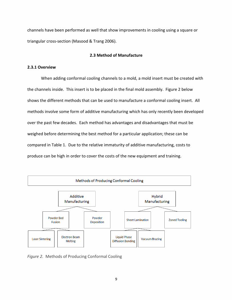
When adding conformal cooling channels to a mold, a mold insert must be created with
the channels inside. This insert is to be placed in the final mold assembly. Figure 2 below
shows the different methods that can be used to manufacture a conformal cooling insert. All
methods involve some form of additive manufacturing which has only recently been developed
over the past few decades. Each method has advantages and disadvantages that must be
weighed before determining the best method for a particular application; these can be
compared in Table 1. Due to the relative immaturity of additive manufacturing, costs to
produce can be high in order to cover the costs of the new equipment and training.
Figure 2. Methods of Producing Conformal Cooling
10
All of these methods typically produce an insert that is “near net-shape” (Dalgarno et al.
2000, p. 132). Further machining, grinding, and polishing are needed for any part cavity
surfaces in order to achieve the desired part finish and dimensions as well as to fit the insert
properly with no coolant leaks or extra plastic flow, called flash, between mating surfaces.
2.3.2 Powder Bed Fusion Methods
The most common method used is powder bed fusion. This uses a bed of powdered
metal in which a computer guided laser selectively melts powder in the shape of a cross-section
of the part to be manufactured. Each layer is melted in sequence then the bed shifts down a
set layer thickness and new powder is spread to be melted for the next layer. This process can
produce near fully dense parts of any complexity. The main limits with powder bed fusion are
the difficulty to remove unsintered powder from inside the part after forming and restrictively
small size of the build platform. Large molds cannot use the powder bed fusion method for
their inserts due to the build platform size limit. These bed fusion methods are all direct
methods as opposed to indirect methods (Karunakaran, Shanmuganathan, Jadhav, Bhadauria,
Pandey 2000) which involve creating objects out of softer resins rather than directly working
with the final metal material.
2.3.3 Powder Deposition
Powder deposition uses powdered metal as well but instead applies the powder only to
the location needed. Powder deposition does not have the limiting factors that powder bed
fusion has since there is no leftover powder to remove. Also, the build platform limit is

11
alleviated as well. The size limit depends only on the work envelope of the robot used to move
the deposition head.
2.3.4 Sheet Lamination Methods
Sheet lamination is also a viable alternative to the powdered metal methods. In this
process, each layer is cut from a thin sheet. The sheets are then diffusion bonded or brazed
together to form a solid stack. For diffusion to occur, the layers must be under high pressure to
keep the mating surfaces in contact with each other (Jacobson & Humpston 2005). This
method has the advantages of quick manufacturing and no limitation of mold geometry
(Walczyk & Dolar 1997). However, a disadvantage is that there can be visible steps along the
axis of the stacked layers requiring further machining and polishing in the area of the part
surface. A major benefit of this method is being able to produce any sized insert. Large molds
that use conformal cooling channels use sheet lamination methods typically with vacuum
brazing to adhere the layers (Beard 2014). Himmer, Techel, Nowotny, and Beyer (2002)
recommend not using methods other than diffusion bonding for die casting or injection
molding applications due to the intense pressures and heats experienced in those processes.
2.3.5 Zoned Tooling
Zoned tooling creates the conformal cooling channels by creating multiple adjacent
inserts called zones. This method is similar to sheet lamination but instead uses multiple large
block inserts to form the mold along the direction perpendicular to the cooling channels. Each
block insert, called a zone, in this method still uses conventional straight-drilled channels that
can be drilled at angles such that they meet the holes in the adjacent zones. This creates a
somewhat more conforming cooling system. However, this method has the major drawbacks

12
of not being fully conformal to the part surface. Also, a tight fit is required between zones to
prevent coolant leakage. Each block still requires further machining to create the part cavity in
addition to all the time involved with drilling the channel holes.
Table 1
Advantages and Disadvantages of Methods of Manufacture
Category Type Advantages Disadvantages
Powder Bed Laser
Sintering
Density comparable to cut material
Flexibili ty for any material
Easier to remove powder from interior
Capable of using very fine powder
Capable of starting and stopping mid-job
Able to inspect process during build
Good thermal conductivity
Better surface finish
Lower energy requirements
Small layer thickness improves accuracy
Insert l imited to bed size
Not suitable for large wal l thicknesses
Internal stresses result requiring anneal ing
Requires build plate base of same material
Must be cut away from build plate base
Powder Bed Electron
Beam Melting
High productivity
Suitable for large inserts
No residual internal stress due to high heat
Less support structure required
Good thermal conductivity
No gas contamination due to vacuum
Good mechanical and fatigue results
Insert l imited to bed size
Difficult to remove powder from interior
Difficult to work with fine powder
High energy requirements due to high heat
Powder Deposition
Insert able to be made of any size
Abil ity to control grain structure
High accuracy
Slow to produce
Poorer finish
Limited material use
Liquid Phase Diffusion
Bonded Sheet
Lamination
Insert able to be made of any size
Fast fabrication
Visible stair-stepping of layers
Reduced accuracy in direction of thick layers
Vacuum Brazing Sheet
Lamination
Insert able to be made of any size
Fast fabrication
Visible stair-stepping of layers
Reduced accuracy in direction of thick layers
Zoned ToolingInsert able to be made of any size
Uses low cost straight-drilled channelsCooling channels not as conforming to part
Advantages and Disadvantages of Methods of Manufacturing Conformal Cooling Channels
(Data derived from Loughborough University 2016, Walczyk & Dolar 1997, Engel 2013)
Additive
Manufacturing
Hybrid
Manufacturing
13
2.4 Aspects of Conformal Cooling Channel Design
Many factors must be accounted for in conformal cooling system design. Among the
factors to consider are the following:
• Cooling channel design
o Turbulent flow
o Cross-sectional area
o Cross-section shape design
o Channel distance from cavity surface
• Coolant type
• Coolant temperature
• Conformal location and extent
o Coolant circuit flow path length
o Coolant weight to be pumped
o Flow restrictions
o Areas to add conformal channels
o Areas to leave conventional channels and methods
o The extent of how conformal to the shape the channels should be
2.4.1 Turbulent Flow
Efficiency of heat transfer is important to achieve the lowest cooling time and thereby
fastest cycle time. Studies of turbulent flow versus laminar flow of the cooling fluid have
repeatedly shown that a turbulent flow provides the most efficient heat transfer rate. To

14
achieve turbulent flow, the Reynold’s number must be met (Reynolds 1894). The following
formula originally developed by George Stokes (Stokes 1851) describes the Reynold’s number
which Reynolds popularized in the late 1800’s:
�� = ���� = �� =�� (1)
Re = Reynold’s number (dimensionless)
ρ (rho) = density of coolant fluid � ����
v = mean velocity of coolant fluid ��� �
D = diameter (m)
µ (mu) = dynamic viscosity of coolant fluid � ��∙��
ν (nu) = kinematic viscosity ���� �
Q = flow rate ���� �
A = cross-sectional area (m2)
Note: Non-circular cross-sections use formulas for hydraulic diameter (DH) in place of diameter
(D). Refer to appendix section 7.3 for formulas of hydraulic diameter for different cross-
sections.
Turbulent flow can be achieved through several different means. Features can be added
to increase the number of eddies formed when flowing around corners or changing directions
15
in the circuit. In some cases, turbulence can be difficult to achieve since the flow rate is
significantly reduced by the flow path length, coolant weight to be pumped, flow restrictions, or
combination of these factors.
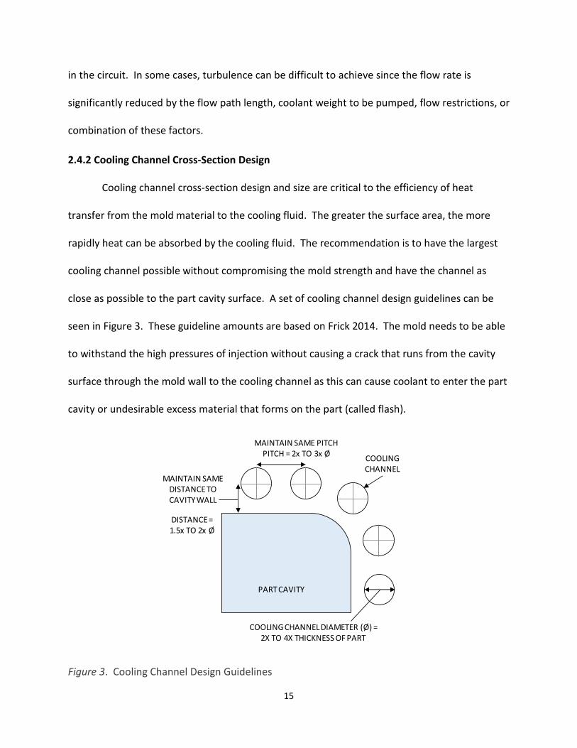
2.4.2 Cooling Channel Cross-Section Design
Cooling channel cross-section design and size are critical to the efficiency of heat
transfer from the mold material to the cooling fluid. The greater the surface area, the more
rapidly heat can be absorbed by the cooling fluid. The recommendation is to have the largest
cooling channel possible without compromising the mold strength and have the channel as
close as possible to the part cavity surface. A set of cooling channel design guidelines can be
seen in Figure 3. These guideline amounts are based on Frick 2014. The mold needs to be able
to withstand the high pressures of injection without causing a crack that runs from the cavity
surface through the mold wall to the cooling channel as this can cause coolant to enter the part
cavity or undesirable excess material that forms on the part (called flash).
Figure 3. Cooling Channel Design Guidelines
MAINTAIN SAME PITCH
PITCH = 2x TO 3x Ø
PART CAVITY
COOLING
CHANNELMAINTAIN SAME
DISTANCE TO
CAVITY WALL
DISTANCE=
1.5x TO 2x Ø
COOLING CHANNEL DIAMETER (Ø) =
2X TO 4X THICKNESS OF PART

16
The cross-sectional shape design is also important for the surface area. Additive
manufacturing allows for any shape of cross-section. Elliptical cross-sections have been shown
to provide better heat transfer than circular cross-sections where the larger surface area is
facing the part cavity and they provide more turbulent flow with a higher Reynold’s number
(Xu, Sachs, Allen, Cima 1998) (Mathey, Penazzi, Schmidt, Rondé-Oustau 2004). Other cross-
sections have been studied as well (Masood, Trang 2006; Hearunyakij, Sontikaew, Sriprapai
2014). See Table 2 for relative impact of cross-section design on the cooling time.
Table 2
Cooling Channel Cross-Sectional Design
DISCLAIMER: Rankings are generalizations and not representative of every case.
Type Cross-sectionCooling Time as a
Percentage of Standard
Relative Rank
(1 is Best)
Conventional Circular 100% -
Circular 78% 4
Elliptical 75% 3
Square 57% 2
Triangular 21% 1
Conformal Circular (0 fins) 87% 4
Finned Circular (3 fins) 80% 3
Finned Circular (5 fins) 77% 2
Finned Circular (7 fins) 69% 1
Milled Groove
Partial ConformalSquare
92%3
Geometric
Conformal
Advanced
Conformal
Cooling Channel Cross-sectional Design (Data derived from Masood, Trang 2006; Hearunyakij et al. 2014; and Mathey et al. 2004)
NOTE: Percentages calculated based on comparison studies within groups below. Further studies
needed to compare all different types proposed with the same mold as a control.
17
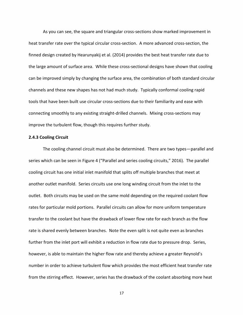
As you can see, the square and triangular cross-sections show marked improvement in
heat transfer rate over the typical circular cross-section. A more advanced cross-section, the
finned design created by Hearunyakij et al. (2014) provides the best heat transfer rate due to
the large amount of surface area. While these cross-sectional designs have shown that cooling
can be improved simply by changing the surface area, the combination of both standard circular
channels and these new shapes has not had much study. Typically conformal cooling rapid
tools that have been built use circular cross-sections due to their familiarity and ease with
connecting smoothly to any existing straight-drilled channels. Mixing cross-sections may
improve the turbulent flow, though this requires further study.
2.4.3 Cooling Circuit
The cooling channel circuit must also be determined. There are two types—parallel and
series which can be seen in Figure 4 (“Parallel and series cooling circuits,” 2016). The parallel
cooling circuit has one initial inlet manifold that splits off multiple branches that meet at
another outlet manifold. Series circuits use one long winding circuit from the inlet to the
outlet. Both circuits may be used on the same mold depending on the required coolant flow
rates for particular mold portions. Parallel circuits can allow for more uniform temperature
transfer to the coolant but have the drawback of lower flow rate for each branch as the flow
rate is shared evenly between branches. Note the even split is not quite even as branches
further from the inlet port will exhibit a reduction in flow rate due to pressure drop. Series,
however, is able to maintain the higher flow rate and thereby achieve a greater Reynold’s
number in order to achieve turbulent flow which provides the most efficient heat transfer rate
from the stirring effect. However, series has the drawback of the coolant absorbing more heat

18
as it travels to the end of the circuit thus preventing the same level of cooling at the end of the
circuit and causing a non-uniform temperature gradient from inlet to outlet. The advantages
and disadvantages shown in Table 3 below may help in determining the best circuit type for a
particular application.
Figure 4. Simple Series and Parallel Mold Cooling Circuits

19
Table 3
Comparison Between Parallel and Series Cooling Circuits
Another consideration for the cooling circuit is the overall length. As the length
increases, the head pressure decreases due to an increased amount of fluid the pump must
push and also frictional resistances. The weight of the fluid in the circuit must be considered.
This can cause a decrease in the flow rate and the efficiency of cooling if the flow rate drops to
Advantages Disadvantages Key Design Points
● Coolant has minimal
temperature increase as it
nears the end of the circuit
● Slower individual flow
rate as number of branches
increases
● Balance branches to achieve
the same flow rate
● Minimal pressure drop
allows for smaller pump
● Uneven cooling since
individual branches exhibit
different flow rates
● Increase diameter to allow for
turbulent flow
● Requires less space and
machining to create circuit
● RestricTon of individual
branch causes reduced
flow rate and cooling to
that area
● BeUer balance of flow rate
to every portion of the
cooling circuit
● Coolant has higher
temperature increase as it
nears the end of the circuit
● Maintaining cross-secTonal
size throughout the circuit
allows for same flow rate
● Able to maintain turbulent
flow throughout full circuit
● Greater pressure drop as
series length increases
● Temperature increase of
coolant should be less than 5°C
● Any restricTons in flow are
easily detected
● Temperature increase of
coolant for precision molds
should be less than 3°C
Parallel
Series
Comparison Between Parallel and Series Cooling Circuits(Data derived from Autodesk Knowledge Network 2016)

20
a point where turbulence is not achieved. See section 2.4.1 for calculating the Reynold’s
number.
2.4.4 Coolant Type and Temperature
The coolant type and temperature are important to consider. The most common
coolant types are water and oil. The temperature of the coolant determines the mold surface
temperature. The temperature recommendation for the mold surface when molding a
particular plastic material may be higher than the boiling point of water at 100°C. For these
applications, oil is used since it will not evaporate within the cooling circuit like water would.
The reason for a higher coolant temperature—and thereby a higher mold surface
temperature—is due to the undesired stress that may result if a particular material is cooled
too rapidly. This stress could cause brittle sections or warpage as the plastic attempts to relieve
stress during final cooling outside the mold. The mold temperature is therefore a primary
determining factor in coolant type. The temperature for the coolant is chosen to be as low as
possible while still making a good part. Typically material suppliers’ recommendations are
followed, but lower temperatures may be possible depending on the application. I suggest that
trials be performed at different temperatures to determine the lowest mold temperature that
can still produce quality parts with good capability indexes (Pp and Ppk). Once a suitable mold
temperature is chosen, the coolant type may be selected.
Other coolant options are to use a mixture of water and a small percentage of glycol.
Glycol can aid cooling by improving the heat transfer rate. Glycol can be an expensive coolant

21
choice and its ratio must be controlled to prevent excess glycol from being in the system.
Excess glycol has the negative effect of decreasing flow rate due to the high viscosity.
The final choice, however, of coolant type may be up to the cost benefit of what
provides the greatest heat transfer at the lowest cost. The simulation may show that glycol-
water mixture may provide faster cooling rate, but if the efficiency improvement is not enough
to justify the cost of the additional glycol then using only water may be the best choice.
2.4.5 Conformal Locations and Extent of Conformality
The placement of conformal channels should be determined from the initial software
analysis studies performed in step one. This data should show where the hottest portions are
on the part that take the longest time to cool down to a safe ejection temperature. Removing
heat from these areas is critical to achieving the goals of implementing conformal cooling.
Mayavaram & Reddy in 2003 discussed how to optimize the design of conformal cooling
channels and developed an algorithmic software based approach. In their approach they
considered the cooling time and temperature uniformity to be the most important constraints
on their design.
Injection mold cooling uniformity is analogous to the Pareto principle—eighty percent of
the cooling required is only located in twenty percent of the part. This is less true of simple
parts than for complex shaped parts. The locations most likely to take longest to cool are those
located furthest from the cooling channels, thick portions of the part or runners such as the
sprue, and any cores or core pins surrounded by plastic. Simple parts on the other hand such as
a square wafer can be easily conformally cooled by the standard straight-drilled method. An
example of this Pareto principle for a conformal cooling application is a blow mold used to

22
create bottles where the neck is the thickest section. A conformally-cooled insert was created
by DMLS for just the neck providing a 75% reduction in cycle time by cooling only this small
portion of the bottle. (Shellabear & Weilhammer 2007). Another example by Thornagel &
Florez in 2011 showed that a reduction of 23% could be achieved in their case study by
providing conformal cooling just to one cylindrical “mandrel-shaped” core.
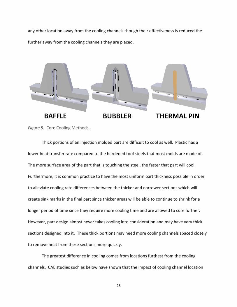
Since they are completely surrounded by plastic, cores are exposed to the most heat
and are difficult to cool. Conventional straight channels cannot cool cores in cases where the
cooling channel diameter would compromise the core strength. Displayed in Figure 5, the
following are three main methods used to cool cores in common practice: baffle, bubbler, and
thermal pin. Baffles and bubblers both use a straight-drilled hole going up into the core. Both
of these methods can restrict the flow rate, though this can be compensated for by increasing
the hole diameter. Baffles create a flow path for coolant by blocking off half of a hole until near
the very end after which coolant can flow around the baffle and back through the other side of
the hole. A common issue with baffles is that they can have coolant flow past a poorly sealed
edge causing little to no cooling to occur at the tip of the baffle. Some baffles can have fins or
grooves to prevent coolant from blowing past the baffle. Bubblers are similar except that they
have a tube inside the drilled hole that carries water into the tip of the hole and out all sides
near the end and flowing back out of the hole on the outside the tube. The thermal pin uses a
pin made of a material with a higher heat transfer rate than the surrounding mold material. A
typical material used is beryllium copper alloy. This pin carries heat away from the core as it is
cooled by the nearby cooling channels. Thermal pins are a better option for small cores and
features. Thermal pins can either be placed in direct contact with the coolant in a channel or in
23
any other location away from the cooling channels though their effectiveness is reduced the
further away from the cooling channels they are placed.
Figure 5. Core Cooling Methods.
Thick portions of an injection molded part are difficult to cool as well. Plastic has a
lower heat transfer rate compared to the hardened tool steels that most molds are made of.
The more surface area of the part that is touching the steel, the faster that part will cool.
Furthermore, it is common practice to have the most uniform part thickness possible in order
to alleviate cooling rate differences between the thicker and narrower sections which will
create sink marks in the final part since thicker areas will be able to continue to shrink for a
longer period of time since they require more cooling time and are allowed to cure further.
However, part design almost never takes cooling into consideration and may have very thick
sections designed into it. These thick portions may need more cooling channels spaced closely
to remove heat from these sections more quickly.
The greatest difference in cooling comes from locations furthest from the cooling
channels. CAE studies such as below have shown that the impact of cooling channel location

24
has the greatest influence on cooling uniformity. This is why conformal cooling channels has
the greatest impact on cooling rate in injection molding. Mohamed, Masood, and Saifullah
(2013) performed analysis that showed that there is a direct relationship between the extent
that cooling channels are conformal and how efficiently the part can cool. Fully conforming
channels gave the best results. Mayavarum & Reddy in 2003 also stated that cycle time
reduction is possible from optimizing areas of inefficient cooling, the hottest locations of the
part. Therefore, I advise that fully conforming cooling channels should be used wherever
conformal channels are determined to be needed. However, gains can be made by using
conformal cooling only in the areas of a mold that need the most cooling. This saves the cost of
redesigning and rebuilding the entire cooling system. By locating conformal channels near thick
sections, in cores, and close to areas that were previously located far away from any channels,
substantial gains can be made since these hot areas are what determine the total length of the
needed cooling time to reach a safe ejection temperature.
2.5 Existing Mold Features
Injection molds have numerous features that can block the addition of channels that
follow the part contour. These can include the following: ejectors, slides, runner location, gate
location, sprue, and proximity of multiple part cavities. There are two prominent issues that
need to be overcome in the mold design in order to implement conformal cooling.
First, any ejectors whose location prevents a cooling channel from being placed near a
critical to cool location of the part should be removed or relocated. Moving or eliminating an
ejector carries the risk of not ejecting the part evenly and causing it to stick or bind during

25
ejection. An option is to add one or more new ejectors nearby to ensure smooth, even
ejection. In some cases, the hindering ejector can be safely removed without causing issue.
Second, slides present a challenge for cooling. Moving slides with conventional straight
channels have flexible hoses attached to allow for free movement. This same flexible hose
technique can be applied to a conformal cooling insert mounted onto a slide though may need
repositioning. Slides need a lot of room for their movement which can make the routing of the
cooling system difficult.
Cavity number presents the next set of challenges. Molds with multiple part cavities
may have the cavities located very closely to each other. Neighboring cavities may have to
share a cooling line between them due to space limitations. Cavities may be spaced further
apart but this can be very costly and is limited by the size of the mold base or the machine size
if the mold base is enlarged. The next issue of multiple cavity molds is the runner system. In
molds with a cold runner system, multiple cavities need to be connected together in a runner
manifold of connecting tubes. This runner system needs to be cooled as well. The entry point
of material into the runner manifold, called the sprue, is typically thicker in diameter than the
runner or even the part in some cases and can take a long time to cool. Conformal cooling
channels must be routed around these runners and cooling must be provided to the sprue. Hot
runner systems, on the other hand, provide a different set of difficulties. With a hot runner, the
manifold is kept at a temperature higher than the plastic melting point which provides another
source of heat in the mold other than the molten material itself. Each point of entry or gate
into the part cavity comes directly out of the hot runner system. Due to the proximity of the
gates to the heating elements in the hot runner, the gate is a hot spot on the part that will cool

26
very little, if at all, until the mold is opened. Hot runner gate location must be located on
surfaces away from features that must be cooled before mold open. Removing the excess heat
that conducts through the mold from the hot runner can reduce the impact of cooling
significantly and may be a limiting factor in how efficiently the parts can cool, with or without
conformal cooling.

27
CHAPTER 3
METHODOLOGY
3.1 Introduction
The proposed approach for implementing conformal cooling on an existing injection
mold to improve a process follows the Six Sigma project steps of DMAIC—Define, Measure,
Analyze, Improve, and Control. DMAIC was developed specifically for ongoing process
improvements using a project based approach. The process builds on earlier project structures
such as PDCA – Plan, Do, Check, Act, with both processes placing heavy emphasis on the
planning stages. Define, Measure, and Analyze could all be considered as planning under the
PDCA model, with the Improve phase considered as Do, and Control as Act. DMAIC is more
thorough than the PDCA method and is widely used in manufacturing industries with a specific
focus on improving quality. The Six Sigma DMAIC structure provides the framework for the
following approach.
Not all injection molding processes may benefit from conformal cooling. This approach
is intended to be applied for molding processes involving three main criteria: poor part quality,
long cooling time, and long remaining product life. Part quality, as mentioned previously, is
significantly affected by the cooling provided by the mold. Any processes that have known
quality issues such as regularly recurring sinks or warp should be considered potential
candidates for improvement. Warpage can affect both appearance and critical part
dimensions. Cooling time affects process selection since the larger the cooling times have
greater potential to be reduced. Long remaining product life based on forecasted volume

28
affects the cost justification for implementing conformal cooling. If only one year of production
remains for a particular part, then it should probably not be considered for conformal cooling.
The longer the remaining forecasted volume there is for a mold then the greater the financial
benefit can be. This is why the majority of research on conformal cooling has been in the area
of new mold design rather than the focus of this approach which is on improving existing
molds. Processes that do not have all of these factors may not benefit from conformal cooling.
Molding processes with known issues of warpage have the greatest potential for improvement
since they can have a potentially major impact on part quality and thereby cost.
3.2 Define
In this stage, the following should be defined: the problem, its scope, the customers,
and any factors critical to quality (CTQ). It is important to define the project first in order to
prevent scope creep—the increase over time of the project’s focus—and to prevent confusion
or miscommunication between project members. This step is an important first part of any
project.
The typical problems that conformal cooling can solve are the problems of warpage,
sink, and long cycle times are described in previous sections. The issue or issues with the
chosen process that the project focusses on should be clearly stated in problem statements. An
example problem statement for a hypothetical process could be as follows:
Problem Statement: Process for part XYZ is known to have issues with warpage causing the
overall part to exhibit curvature that can deviate beyond the part specifications. Also, the
warpage can cause the small arms of the part not to fit properly in assembly. This causes scrap

29
of the part itself and in some cases scrap of the mating part due to damage in assembly.
Rework of assembled components and time spent sorting inventory all add to the costs of poor
quality associated with the warpage.
Specific goals should be established based on the problem statement or statements and
will be based on key improvement metrics of the chosen process. These goals should be
specific and similar to the following:
• Reduce part warpage to a level that is acceptable by the end customer and under
control. Acceptable by the end customer means that the part meets the customer
drawing tolerance, the process capability is high enough to meet industry requirements
such as automotive or medical requirements, the part is functional, and that the part
meets any other customer quality concerns. Under control means that the dimensional
variance falls within set upper and lower control limits, thus reducing or eliminating
defects.
• Reduce part sink marks to a level that is acceptable by the end customer and under
control. Acceptable by the end customer means that the part meets the customer
inspection standard, that the part is visually acceptable, and that it meets any other
customer quality concerns. Under control means that the part visual quality does not
deviate to a condition worse than a control boundary sample. A boundary sample is
recommended due to the difficulty of determining a sink level. The boundary can either
be an actual part, a photograph, or other means of easily determining comparing the
appearance of the part against a standard.

30
• Reduce process cycle time by at least a reduction of a certain percentage. This
percentage should be determined based on a goal to free up line capacity to run more
of this process’s product, other products, or new products on the same line as the
process chosen for the project.
The goals above, however, are generic and should be adjusted to any specific company
goals such as return on investment and other internal company targets. The goals must be
specific or else there will be confusion, lack of direction, and difficulty in determining how
successful the project was after it has been completed. For instance, a target cycle time
reduction amount could be at least a reduction of 20%. Also, dimensional requirements will
vary depending on the type of product such as the very tight tolerance and capability
requirements found in medical applications.
The scope of the project will be one injection molding process. The project will focus on
the mold cooling system design’s impact on the overall injection molding process. A typical
injection molding process includes only one mold. This mold may have multiple cavities
producing multiple parts at once, either as duplicates, symmetrical parts, or unique parts. All
cavities will need to be considered individually in the design of a new cooling system but also as
a system. In some cases multiple molds may exist to create the same product due to high
volume requirements. In the case of multiple molds producing the same parts, these should all
be considered within the scope of the project though modification of each will have to be
sequential due to capacity constraints, thus increasing project lead time. Each of the duplicate
molds should be nearly identical in most cases and thus the same cooling system design can
apply to the replicate molds.

31
The customers for the project should include external and internal customers. The
external customers are typically the purchasers of the final product. The internal customers are
any downstream finishing or assembly operations that the part must go through such as
assembly, coating, or painting. All customers should be listed and any potential impacts that
this project will have on the customers.
From the goals above, CTQs or critical-to-quality factors, of the process are determined.
Using the CTQ definition structure provided by Simon (2001), the following are example CTQs:
CTQ: Part Warpage
CTQ Measures: Length of a feature, distance between features, profile of a feature
CTQ Specification: Lengths and distances fall within tolerance per customer drawing and
capably within company defined control limits with a process capability Ppk of 1.33 or
greater. Profile shape deviation is within tolerance per customer drawing and capably
within company defined control limits with a process capability Ppk of 1.33 or greater
Defect: Length of feature or distance between features too small. Profile shape
deviation too large
Unit: 1 part
Opportunity: 1 per each dimension or profile requirement on the part
CTQ: Part Surface Appearance
CTQ Measures: Sink mark appearance
CTQ Specification: No sink mark visible on part surface

32
Defect: Visible sink mark
Unit: 1 part
Opportunity: 1 per each part feature opposite an appearance surface
CTQ: Process Cycle Time
CTQ Measures: Time length of cycle
CTQ Specification: Company dependent, typically a function of part cost, volume, and
capacity
Defect: Cycle time too long
Unit: 1 cycle
Opportunity: 1 per cycle
3.3 Measure
3.3.1 Overview and Data to Measure
This step establishes the baseline for the critical to quality factors. Current part
warpage, part sinks, and cycle time should be measured. Also, all relevant process data should
be collected from the current process to aid in determining a new cooling system design.
Process and part conditions after improvements have been made will be compared against the
baselines established in this step. It may be difficult to obtain reliable measurements of some
part features. In these cases, an outside metrology lab is recommended for acquiring reliable
data and establishing a repeatable measurement system.
33
If there is a known issue with warpage in the part, knowing the deviation of important
part dimensions can be beneficial especially if the software analysis shows that it is a result of
non-uniform cooling. Measurements of all critical dimensions as well as any dimensions that
can be used to better characterize the warpage that is occurring should be taken. Also,
measurements of the part after it is immediately removed from the mold and still warm can be
taken to compare against cold part measurements to better see how much the part is changing
during cooling. Such warpage data can be beneficial in providing cost justification for the
project.
Part sink data can be difficult to quantify since sink marks are a visual defect. Different
methods have been used to determine good versus no good part condition such as sample
parts. A boundary sample is recommended due to the difficulty of determining a sink level.
Since sample parts can become damaged, the boundary can be a photograph instead of a
physical part. Samples should be kept of the current condition of parts for later visual
comparison.
The cycle time is affected by many processing variables. Cooling time and the variables
that affect it are the primary focus for this project. Therefore, all the relevant physical data
should be collected from the existing injection molding process. The following information
should be collected:
• Cycle time
• Cooling time
• Temperature of the part at mold open

34
• Temperature of the mold surface immediately after mold open
o Temperature on both mold halves
o Temperature near the part cavity and away from the cavity
• Temperature of the coolant for each circuit
• Flow rates of each cooling circuit
• Dimensional data of important part features
• Dimensional shrinkage difference between mold steel and part
• Warpage direction of the whole part and its features
• Current mold design 3D digital data
It should be noted that the 3D data of the mold is the most important data to collect.
Without having the digital mold data it will not be possible to perform any software analysis of
the current mold design. This makes it very difficult to prove that any new conformal cooling
system design is better than the current design since there would not be that data to show the
comparison of one design against another.
3.3.2 Hypothetical Data
Hypothetical measurement data is shown in the tables below for the data listed above.
This is to show the type of data that is representative of the Measure phase. Table 4 shows the
results of measuring the current process, while Table 5 lists out hypothetical data taken from
measuring the part. Note that mold measurements are included at the bottom of Table 5 for
comparison against the part after shrinkage of the plastic material occurs. This data is purely
hypothetical. Any resemblance to actual mold data taken is coincidental and does not disclose
any proprietary data.

35
Table 4
Example Hypothetical Process Measurement Data
Process Name:
Cycle time:
Cavity 1 98°C
Cavity 2 97°C
Movable side near part cavity 88°C
Movable side away from cavity 87°C
Stationary side near cavity 88°C
Stationary side away from cavity 87°C
Movable side circuit 1 87°C
Movable side circuit 2 87°C
Stationary side circuit 1 87°C
Stationary side circuit 2 (chiller) 20°C
XYZ Part
45.7 seconds
Example Hypothetical Process Measurements Data(Data derived from personal experience in injection molding)
Temperature of part at mold
open:
Temperature of mold surfaces
at mold open
Temperature of coolant

36
Table 5
Example Hypothetical Feature Measurements Data
3.4 Analyze
In this phase, the data collected will be analyzed to assess the root causes of the issues
with the process. From the data taken, process capability should be found for each key feature.
Then the 3D mold data should be analyzed for cooling efficiency to see if unbalanced cooling
exists. This should be used to determine why the part is warping as it is. All possible causes
should be listed out based on this analysis.
Sample
A. Curvature deviation
(1.10-1.30mm)
B. Arm to arm
(200.0-210.0mm)
C. Sink level
(pass:O, fail:X)
D. Track width
(4.00-4.25mm)
1 1.32 203.3 O 4.07 A. Measurement using check gauge
2 1.38 203.5 O 4.00 B. Measurement using long calipers
3 1.30 203.7 O 4.10 C. Visual inspection near stripe-board
4 1.26 207.5 O 3.97 D. Pin gauges at narrowest point
5 1.28 203.8 O 4.01
6 1.34 206.3 O 3.96
7 1.46 199.6 X 4.00 The part warpage is cupped or concave
8 1.44 201.5 X 4.10 on the side corresponding to the
9 1.30 205.9 O 4.09 stationary mold half. This causes the
10 1.42 200.8 X 4.01 arms to be closer together.
11 1.36 203.8 X 3.99
12 1.28 207.1 O 4.04 The track on the part also is warped so
13 1.22 207.2 O 3.99 that it is tighter towards the middle.
14 1.40 202.3 X 4.08
15 1.26 206.2 O 4.06
16 1.28 206.3 O 4.01
17 1.42 199.9 X 4.14
18 1.42 199.7 X 4.00
19 1.38 205.9 O 4.08
20 1.32 206.4 O 4.01
21 1.32 205.1 O 4.07
22 1.28 200.0 O 4.04
23 1.24 207.8 O 4.03
24 1.36 206.9 O 4.00
25 1.44 200.0 X 3.97
26 1.46 198.8 X 4.06
27 1.32 204.3 O 4.10
28 1.34 201.6 O 4.00
29 1.36 202.6 X 4.01
30 1.30 204.8 O 3.98
Mold 1.12 208.2 N/A 4.22
Example Hypothetical Feature Measurements Data(Data derived from personal experience in injection molding)
NOTES:
37
From the analysis, effective countermeasures should be determined to address all
possible root causes of the process issues. Then a plan with due dates for each
countermeasure should be established that will be carried out in the Improve phase. Whether
conformal cooling will be an effective countermeasure for the causes of the part issues depends
on the data and the process. Other options may be better suited or more cost effective.
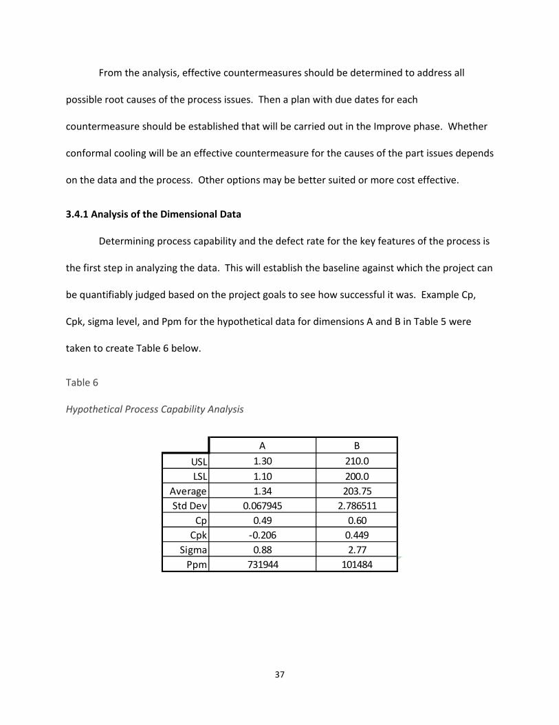
3.4.1 Analysis of the Dimensional Data
Determining process capability and the defect rate for the key features of the process is
the first step in analyzing the data. This will establish the baseline against which the project can
be quantifiably judged based on the project goals to see how successful it was. Example Cp,
Cpk, sigma level, and Ppm for the hypothetical data for dimensions A and B in Table 5 were
taken to create Table 6 below.
Table 6
Hypothetical Process Capability Analysis
A B
USL 1.30 210.0
LSL 1.10 200.0
Average 1.34 203.75
Std Dev 0.067945 2.786511
Cp 0.49 0.60
Cpk -0.206 0.449
Sigma 0.88 2.77
Ppm 731944 101484

38
3.4.2 Analysis of the 3D Mold Data
The major goal of this portion of the Analyze phase is to be able to accurately represent
the current condition through software simulation and assess the root causes of the issues in
the process based on the simulation. Adjustments to initial simulation should be made in order
to accurately reflect the data taken from the actual process, such as temperature of the part at
ejection. From this software analysis, a new design can be developed as a countermeasure for
the issues. Taking this set of parameters, with the current mold 3D data as a baseline, will
provide confidence for the simulation of new mold 3D data from any cooling channel design
iterations. This is one of the most effective ways to prove the viability of conformal cooling
relative to cost.
Typically, when molds are manufactured, the mold is created in 3D design software first
in order to anticipate potential design problems with the mold, iterate designs, and make
changes before any material has been cut. The most up-to-date data should be acquired that
includes any changes made to the mold after start of mass production. If mold data does not
exist, it can be recreated, at a cost, from scans of the mold and any mold drawings as an aid.
Even a simplified 3D representation of the mold’s part cavities and cooling channels can be
beneficial for analysis. With the mold data in-hand, simulation can then be performed using
one of several available software packages or can be outsourced to a CAE company to perform
this initial analysis. Through this analysis the cooling time, hot spots, and warpage can be
estimated using either the boundary element method (BEM) or the finite element method
(FEM). Most software will display the part with a temperature gradient of colors with red for
the highest heat portions of the part, green in the middle, and blue at the coldest points of the

39
part. The overall range between coldest and hottest portions of the part is a good indicator of
cooling uniformity. These results can be used to determine the root causes of the process
issues. An example analysis of a hypothetical part’s temperature after the elapsed cooling time
can be seen in Figure 6 below. Note that there are hot spots in the thick sections at the base of
the arms.
Figure 6. Example Cooling Analysis
Once the adjustments have been made, the simulation parameters should be logged for
future use in the new design iterations. It may take multiple simulations of parameter
adjustments until a result that closely resembles the actual part and process data is achieved.
These parameters will be used for simulations performed on any new design iterations so that
accurate results can be achieved.
40
3.4.3 Listing Root Causes and Determining Countermeasures
After the data has been analyzed, the root causes should be listed. It may be helpful to
use a fishbone diagram at this point to help with listing possible causes. The most likely root
causes can be determined and listed. Here is an example list of most likely root causes:
• Less surface area on inner concave side of part prevents even heat transfer resulting in
longer cooling and more shrinkage on the inner side. This increases curvature of the
part.
• Poor heat conduction from area near base of part arms resulting in trapped heat and
poor cooling causing arms to warp inward. This area is located furthest away from
cooling channels.
• Poor heat conduction from steel rib forming inner track preventing uniform cooling of
plastic ribs forming the track causing track to be warped inward near the middle. The
inner portion of the track is further away from the cooling channels than the sides.
A project meeting should be held to determine the countermeasures. Once
determined, these countermeasures should be listed and separated into short-term and long-
term countermeasures (STCM and LTCM respectively). Example countermeasures from this
analysis are as follows:
• STCM: Trial run process using a lower coolant temperature setting on the stationary
mold half as an initial cooling improvement based on the analysis to aid with part
curvature.

41
• LTCM: Add better cooling on the stationary mold half towards the middle of the part
inside the concave portion of its curvature. This will further improve the part curvature.
• LTCM: Add better cooling near the thick portions at the inside base of the arms of the
part.
• LTCM: Remove plastic material in thicker portion of the arms of the part by adding ribs.
• LTCM: Increase surface area of the part on inner concave surface by adding ribs.
Cost quoting can take place for each long-term countermeasure to determine if it is a
viable option and whether it should be implemented. Further development of
countermeasures and a plan for each should take place. A schedule should be created after
countermeasure development with due dates for implementing the countermeasures, assigned
responsibilities, and a planned budget. The specifics of implementation, due date, and cost will
all be determined from the development of each countermeasure.
3.4.4 Developing Conformal Cooling Countermeasure
Development of the countermeasure should take place to estimate how long it will take
and the specifics of the implementation. The main countermeasure this thesis focuses on is
conformal cooling. The conformal cooling countermeasure design will be generated through
software or created by hand in multiple iterations, each followed by the simulation of the
design’s effectiveness compared against the current process. Finally, the choice of design will
be made.
Creating the new design is conducted using 3D software. The mold designer may use
automatic algorithms to quickly iterate different conformal cooling channel layouts provided by
different software packages. During development of the new conformal cooling channels,

42
multiple iterations may be simulated to determine the most optimal solution. Once the most
optimal design is selected, it should be compared against the simulation results of the current
mold condition. This will help determine the estimated cost savings and quality improvements
and is vital for justification of implementing the new design. Uniformity of the cooling should
be considered in order to assess estimated part quality improvement by eliminating or
alleviating sinks and warpage. If the design does not provide sufficient improvement for
justifying the implementation, further design iterations should be carried out. Refer to Chapter
2 for various design considerations such as the existing mold features and the method of
manufacturing the conformal cooling channels.
A key point to consider here is the extent of conformality. Previously, a cooling Pareto
principle was suggested in Chapter 2 to act as a guide in choosing the extent of conformality in
the new design. The cost justification for a complete overhaul of a mold cooling system to add
conformal cooling may be difficult due to the high expense. However, only adding conformal
cooling in the most critical areas could be cost effective. A simplified hypothetical example of
this type of analysis would be to consider the mold with the hot spot visible in Figure 7 below.
The cost to add conformal cooling to the entire body of the part could be as high as $30,000
while adding a conformally cooled insert around just the hottest location of the part may only
cost $8,500. Figure 7 demonstrates a simplistic comparison of the part temperature with a fully
conformal circuit and the same part with localized conformal cooling. The more expensive
option could, hypothetically, only provide 1.5 seconds more reduction in cooling time in
addition to the localized cooling’s reduction of 11.4 seconds.

43
Figure 7 Cooling System Design Comparison – Fully Versus Partial
3.4.5 Developing Other Countermeasures
Other countermeasures outside of conformal cooling may be considered such as
improved core cooling (refer to the methods discussed in section 2.4.5), increased surface area,
enlarged cooling channels by re-drilling, change in coolant, increased coolant flow rate, and
reduction in plastic part thickness. These methods are not the focus of this paper but are
mentioned as alternatives to conformal cooling while still producing more uniform and efficient
cooling. In some mold improvement cases, these options may be the most cost effective,
though not necessarily provide the highest quality results.
3.4.6 Cost Justification
Justification for implementing conformal cooling in an existing mold comes from the
comparison between the current baseline process and proposed performance measures.
Uniform cooling provides potential improvement in part quality. Cycle time reduction by

44
decreasing the required cooling time results in a reduction in required machine capacity.
Without cost justification, moving forward with the implementation will not happen outside of
an academic context.
Quality of the part produced is increasingly important for production. The costs related
to poor quality can be substantial—20-40% of sales [Evans & Lindsay]. Some costs are indirect
such as loss of business through lack of customer satisfaction with the end product, while other
costs are direct such as warranty claims and scrap. Poor part quality related to improper
cooling is typically in the form of sinks or warpage since the material shrinkage is not uniform
due to the non-uniform cooling. Depending on part function, this issue can cause any of the
above costs due to poor quality. In the case of an automotive application, poor part quality
could even be the cause of a vehicle recall which can have very high costs.
Since quality is so important, the software simulation results of the proposed design
should be carefully analyzed to determine the impact to the part quality. Any areas of known
warpage should be inspected for improvement with the new conformal cooling channels. Also,
if sink marks are problematic, the cooling in those problem areas should also be closely
inspected in the 3D software to verify that the new design improves cooling uniformity, cooling
time, or both. If this analysis shows significant improvement through the use of a new
conformal cooling system, the savings from this could be justification enough to avoid the
potentially high costs associated with producing poor quality parts, not to mention potential
loss of business due to customer dissatisfaction with the product. To aid in determining this
cost savings, Figure 8 represents the analysis of ROI and savings based on the COPQ (costs of
poor quality) over the remaining lifetime of the product. As a comparison, Figure 9 provides a

45
similar analysis of the breakeven point between conventional and conformal cooling mold
designs. Again, the savings would be much higher when starting new production with
conformal cooling. This is why the focus of current research has been on new development
rather than improvement of existing processes.
Figure 8. Implementation ROI Analysis
COPQ + Overhead
Overhead
Implementation Cost
1/2017 7/2017 1/2018 7/2018 1/2019 7/2019 1/2020 7/2020 1/2021
Co
sts
Production Volume
Implementation ROI and Savings
ROI Point ≈ 18mo.
Savings
End of LifeNow

46
Figure 9. Conformal Cooling Break Even Analysis for New Mold
Machine capacity is also a primary benefit of conformal cooling due to the reduction in
cycle time that can be achieved. Cooling time can take up to 80% of the overall cycle time.
Thus, cycle time is limited by the portion that takes longest to cool which acts as a cooling
bottleneck. By increasing the cooling efficiency by locating cooling channels close to the part
surface all along the contour of the part, bottleneck hot spots can be eliminated and the cooling
time can be optimized. Substantial gains have been shown to be possible with conformal
cooling times. Cycle time reduction allows for more time to be available to run more parts.
This is the benefit of faster cooling time.
The following serves as an example of calculating capacity savings from cycle time
reduction. Suppose a particular injection machine runs two single cavity molds twenty-four
hours per day. Mold A runs a cycle time of 35.0 seconds, while Mold B runs at a cycle time of
32.0 seconds. The forecasted volume of Mold A is 9.0 hours of runtime per day. Mold B needs
Fixed Cost Conventional
Fixed Cost Conformal
Revenue
Cost Conventional
Cost Conformal
Co
sts
an
d R
eve
nu
e
Production Volume
Conformal Cooling Break Even Analysis
Break Even Point
Conformal
Break Even Point
Conventional

47
to run for 10.0 hours per day. The scheduled downtime for this machine allows for
changeovers and machine preventative maintenance at an amount of 0.8 hrs per day. Suppose
the company running these machines wishes to quote new business for a Mold C to run on this
machine. The total time, 9.0 + 10.0 + 0.8, needed currently is 19.8 hours leaving only 4.2
available for another mold. Given a quoted Mold C volume of 6 hours per day, the company
will need to purchase a new machine in order to accommodate this forecasted volume and still
leave enough time for changeovers and maintenance. The new machine is quoted at $180,000
for purchasing and install.
Suppose the company then implements conformal cooling for Mold A since it has the
longest cycle time and thickest part sections. The cost to implement is $72,000 with a
predicted cycle time reduction of 25% which would be a new cycle time of 26.3 seconds.
Performing the calculations:
Current volume produced in 9hrs = (3600sec * 9hrs / 35sec) = 925 pieces
Rewrite to solve for time in hours = 925 pieces * 35 sec / 3600 sec = 9 hrs required
Solve for time in hours using projected cycle time = 925 pieces * 26.3 sec / 3600 sec = 6.8 hrs
required
Old time available = 24 - 9.0 - 10.0 - 0.8 = 4.2 hours
Anticipated time available = 24 - 6.8 - 10.0 - 0.8 = 6.4 hours
With this simple calculation, the machine is projected to have capacity to run Mold C
with 0.4 hours to spare. This would save the cost of purchasing a new injection machine and

48
installing. The savings well justify the cost of implementation of conformal cooling channels.
The company proceeds with the implementation. After completion, Mold A tests out at a new
actual cycle time value of 27.7 seconds, a 20.8% reduction. While this is substantial, the
reduction is less than anticipated. The calculation was performed again using the actual cycle
time:
Solve for time in hours using new cycle time = 925 pieces * 27.7 sec / 3600 sec = 7.1 hrs
required
Old time required = 9.0 hrs
New time required = 7.1 hrs
Old time available = 24 - 9.0 - 10.0 - 0.8 = 4.2 hours
New time available = 24 - 7.1 - 10.0 - 0.8 = 6.1 hours
This means that the machine has projected capacity to run the new Mold C. The cost of
the new injection machine is saved and the new business can be accommodated. The cost
savings is the difference between the cost of a new machine and the cost of implementing the
conformal cooling; calculation below:
Total cost savings = $180,000 – $72,000 = $108,000
This example serves as a simple method to justify the cost of implementing conformal cooling
channels in an existing mold.
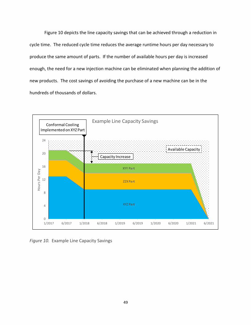
49
Figure 10 depicts the line capacity savings that can be achieved through a reduction in
cycle time. The reduced cycle time reduces the average runtime hours per day necessary to
produce the same amount of parts. If the number of available hours per day is increased
enough, the need for a new injection machine can be eliminated when planning the addition of
new products. The cost savings of avoiding the purchase of a new machine can be in the
hundreds of thousands of dollars.
Figure 10. Example Line Capacity Savings
ZZX Part
XYZ Part
XYY Part
0
4
8
12
16
20
24
1/2017 6/2017 1/2018 6/2018 1/2019 6/2019 1/2020 6/2020 1/2021 6/2021
Ho
urs
Pe
r D
ay
Example Line Capacity Savings
Available Capacity
Conformal Cooling
Implemented on XYZ Part
Capacity Increase

50
3.5 Improve
3.5.1 Overview
This step involves the actual work done to improve the process by carrying out all the
countermeasures determined in the Analyze phase. Steps involved in implementing the
conformal cooling countermeasure are the insert creation, installation of the new mold insert
or inserts into the mold, and finally testing to see the effectiveness of the new cooling system.
3.5.2 Modify the Mold
Once an improvement in design has been approved by the project team, the
justification made, and the project approved, the next step in the implementation is to modify
the mold. In most cases, an insert will be created through one of the means of manufacture
mentioned in chapter 2. The method chosen will determine the cost and lead time and have a
substantial impact on the project’s overall lead time. The new conformal cooling mold inserts
need to be produced and will replace existing inserts or existing solid portions of the mold. A
number of companies are offering their services to produce conformal cooling inserts using the
previously discussed methods. The new components may take a few weeks to produce
depending on the method and scale of the implementation.
Once the inserts are received, installing them into the mold is next. Depending on the
extent of the modifications and the project team’s available resources, this may be done at the
insert vendor or in-house. Installation requires a tight fit to prevent any leakage between mold
inserts. The fit of any new inserts will have to be confirmed to make sure that good parting line
seal-off is made to prevent excess plastic from causing flash or a possible coolant leak. Other

51
modifications may be required such as drilling new standard cooling lines, enlarging existing
standard cooling lines, or adding a new cooling circuit manifold to accommodate any increase
in the number of cooling circuits. These additional modifications may be possible to perform
prior to delivery of the new inserts to decrease the time taken to implement. The modifications
depend on the chosen countermeasures in the Analyze step.
3.5.3 Testing
The mold is now modified and a trial should be ran at the new reduced cycle time. The
mold trial should be ran using the new chosen process parameters based on the software
simulation. Before any parts are ran, a measurement of the fluid flow rate should be made on
each loop of the cooling system. After the trial starts, reprocessing may be required and
adjustments made to these parameters to obtain a good part. During the trial, record all of the
same data that was recorded during the initial trials of the previous mold condition. The most
important data sets to collect are part quality results and the time taken to reach the same part
ejection temperature as at the previous condition which will show the reduction in cooling
time. Samples should be taken at varying cooling times starting with the original setup and
slowly reducing until the part ejection temperature reads the same as previously. However,
further cooling time reduction should be tested past this point since the new cooling circuits
may allow for better part quality at a higher ejection temperature. The new cooling time may
be lower or higher than the anticipated value given by the simulation software. All trial
conditions should be gauged to see the effect of the new conformal cooling channels.
Any dimensional tuning that may be required should follow this initial trial. The mold
may require some minor electrostatic discharge machining (EDM) work, grinding, or polishing
52
to achieve the desired part dimensions and surface quality with the new mold inserts. In some
cases, the inserts would be sent back to the vendor for tuning and then trialed again.
After the trials, a capability study of the sample parts should be completed to determine
the variability of the parts using the new cooling system. Measurements of the process
conditions should be taken as well so that comparison against the original process can be made
and assessment of how well the goals were met. Once part quality is acceptable, process
capability is acceptable, and the settings have been logged and saved, the next step can begin.
3.6 Control
3.6.1 Overview
After improving the process, steps should be taken to maintain the quality and cycle
time at the reduced level. The Control step of the DMAIC process involves setting up the
procedures, controls, and countermeasure plans for maintaining the new improved level.
3.6.2 Establish SPC
If statistical process control (SPC) was not originally established for the mold, it would
be very beneficial to establish a system now. This is especially important if one of the main
goals of the project is to reduce warpage. Any deviation in cooling can result in warpage that
grows and starts to drift towards an out of specification condition which could cause scrap. The
SPC system will allow for correcting and addressing any issues before any defective product is
made. A typical SPC chart is shown in Figure 11 for a dimension with a specification of 10.8
±0.10mm. The example would be filled out by hand each day on the line after performing daily
quality checks. In the example, a callout is shown for one of the data points that went beyond

53
the upper control limit stating that some adjustment was made to the process to correct the
trend.
Figure 11. SPC Example Chart
3.6.3 Establish Preventative Maintenance
There are several typical causes of dimensional deviation related to cooling. One cause
of process variation is flow restrictions from grime build-up in hoses, channels, or fittings.
Another main cause of cooling issues is malfunction of mold temperature control equipment
such as pump wear or heater failure. The recommended controls for these causes are
preventative maintenance actions performed on a regular schedule. The following prevention
actions should be scheduled on a regular basis:
• Running cleaning solution through all mold cooling channel circuits
• Running cleaning solution through hoses and piping on the process line
Month:
Part Name:
Part Number:
Shift:
Item Spec. Tol. Scale 1 2 3 4 5 6 7 8 9 10 11 12 13 14 15 16 17 18
10.92
10.88
10.84
10.8
10.76
10.72
10.68
CalloutLegend:
Control Limit
Spec. Limit
NominalWidget XYZ
00123-456
10.8 ±0.10Arm to arm width
Days of the Month
2
February QUALITY CHECK SHEET

54
• Cleaning or replacing filters on process water supply lines. If filtration is not currently
used for the water supply, filters should be added as part of the control activity.
• Cleaning or replacing filters on mold temperature control equipment
• Regular maintenance of mold temperature control equipment per manufacturers’
recommendations
These actions will help to prevent process deviation and, along with the SPC, will prevent
outflow of bad product to the customer.
55
CHAPTER 4
CONCLUSIONS
This approach outlined the steps for implementing conformal cooling channels on
existing injection molds using the proven Six Sigma methodology of DMAIC. DMAIC was chosen
as a systematic project-based method to ensure the production of high quality parts for the
customer.
The problem statement, project scope, customers, and critical quality factors was
discussed in the Define phase. The main problems that conformal cooling can solve are
warpage and sinks due to non-uniform and inefficient cooling of portions of an injection mold.
Specific, data-driven goals were set for improving these problems.
In the Measure phase, the numerous important factors were listed that should be
measured. The important factors are all the relevant elements of the existing injection molding
process. Representative data was given for the expected results of this phase.
The Analyze phase involved discussion of the data analysis, root cause determination,
and development of countermeasure activity to address the root causes. Some likely root
causes are poor heat conduction due to distance from cooling channels or a difference in
surface area of different part features. The conformal cooling countermeasure development
was discussed. Cost justification for implementing the improvements were also considered. A
key point is that conformal cooling may only be necessary in a few areas rather than the entire
mold. This can greatly reduce the costs required.
56
Improve phase covered the actual implementation of conformal cooling in the mold.
Mold modification, fitting, and testing are a part of this step. Measurements of the parts and
the process are taken and possibly followed by minor tuning of the new inserts to achieve the
proper part dimensions.
Finally, the Control phase reviewed the methods for maintaining the resulting
improvements from the previous steps. A simple SPC method was demonstrated and possible
maintenance activities discussed to prevent cooling issues that may cause variation in the
process.
This approach provides a quality-driven and data-driven method of implementing
conformal cooling and should provide a means for any injection molding company to improve
part quality and reduce cycle time for existing molds.

57
CHAPTER 5
FUTURE WORK
In the past, the technologies used to produce conformal cooling had issues with poor
strength and coolant leaks, making them unsuitable for mass production. These concerns with
conformal cooling manufacturability have been alleviated through recent developments in the
additive manufacture of metal parts as discussed in Chapter 2. Laser sintering of powdered
metal and vacuum brazing of metal sheets prove to be the best state of the art methods for
creating conformally-cooled mold inserts. Most current work has focused on producing new
molds with conformal cooling through these additive manufacturing methods.
Given the lack of available scholarly evidence for implementing conformal cooling
channels in pre-existing mass production tooling, an actual implementation of this method
should be conducted to further add to the evidence in support of conformal cooling that the
software analysis predicts from various studies. Due to lack of resources, an actual case study
of a mold was not able to be done at the time of this writing.
Replicate implementations of conformal cooling need to be performed using this
approach and refined as needed by the application. This is especially important to further
convince injection molding companies that conformal cooling is not only possible, but a
practical alternative to achieve excellent part quality and dramatic cost savings.
Other topics for further research in conformal cooling are as follows:
• Lifetime studies of conformal cooling channels produced through the different methods
discussed in Chapter 2 to see how long each method lasts in a production environment.

58
• Comparison of various cooling channel shapes in cooling the same part design
• Envelope cooling design such that an envelope completely surrounding the part cavity
and in the shape of the part is used to flow coolant around the part in a perfectly
conformal cooling method rather than only through several cooling tubes.
• Comparison of various lattice methods to support the structure of an envelope cooling
network around the part cavity.
A conformal cooling insert lifetime study should be carried out to compare the wear
over time for each of the following methods: laser sintering, electron beam melting, liquid
phase diffusion bonding, vacuum brazing, and zoned tooling. This study should attempt to
answer the question of how long, in molding cycles, do each method of manufacture last in a
mass production environment. The method of determining insert life should be based on the
first occurrence of either cracking, coolant leakage, or flash.
Some work has been done to compare circular cooling channel cross-sections against
other designs, but no study has comprehensively compared all previously mentioned cross-
section types together. This study should include all of the following cross-sections: circular,
elliptical, square, triangular, 3-finned circular, 5-finned circular, 7-finned circular, and milled
groove square. The study should specifically control the part design, cooling channel circuit
layout, coolant type, and molding material to be the same for all cross-section designs. The
questions to answer from this study are which cross-section provides the most heat transfer,
whether turbulence created or surface area of the cross-section has the most statistically
significant impact on heat transfer, and which cross-section has the best strength.

59
Envelope cooling channel design should be studied. With recent improvements in
accuracy and strength of additive manufacturing, the ability to create complex designs is now
possible. The freeform fabrication of lattice structures was suggested as a method for
conformal cooling in 1999 by Gervasi, Milkowski, Canino, and Zick. An envelope of this sponge-
like lattice structure could be formed that completely surrounds the part cavity in an injection
mold. Coolant could be pumped through this envelope to provide the most conformal cooling
channel design possible. Gervasi et al. (1999) also suggested that a lattice gradient could be
created such that thicker bars in the lattice could be used where greater strength might be
needed. A gradient where thicker, stronger lattice work could be used nearer the part cavity
wall. Lattice with thinner, weaker bars could be used further away from the cavity surface to
support more rapid fluid flow if needed. This lattice work could either replace or complement
the existing channel design. Also, multiple lattice types should be studied. The questions that
an additional lattice study should answer are which lattice type provides the most strength and
which lattice type provides the most efficient cooling.

60
REFERENCES
Ashley, S. (1997, March 3). From CAD art to rapid metal tools. Mechanical Engineering, 119(3),
82-87.
Au, K. M., Yu, K. M., & Chiu, W. K. (2011, January 2). Visibility-Based Conformal Cooling
Channel Generation for Rapid Tooling. Computer-Aided Design, 43(4), 356-373.
Au, K. M., & Yu, K. M. (2011). Modeling of Multi-Connected Porous Passageway for Mould
Cooling. Computer-Aided Design, 43(8), 989-1000.
Autodesk Knowledge Network. (2016, June 27). Parallel and Series Cooling Circuits. Retrieved
from https://knowledge.autodesk.com/support/moldflow-insight/learn-
explore/caas/CloudHelp/cloudhelp/2017/ENU/MoldflowInsight/files/GUID-2DF9E5FA-
563F-42F1-9847-F0AEA5F48E6D-htm.html
Bak, J. V., Baldwin, R., Beals, J. T., Dardas, Z. A., & Schmidt, W. R. (2002, November). U.S.
Patent Application No. 09/827,046. Washington, DC: U.S. Patent and Trademark Office.
Beard, R. (2014, June). Why Conformal Cooling Makes $ense. Plastics Technology, June 2014.
Retrieved from http://www.ptonline.com/articles/why-conformal-cooling-makes-ense
Boivie, K., Dolinsek, S., Homar, D. (2011, September). Hybrid Manufacturing; Integration of
Additive Technologies for Competitive Production of Complex Tools and Products.
Proceedings from the International Research/Expert Conference. 12-18 September.
Prague, CZ. 53-56.
Dalgarno, K. W., Stewart, T. D., & Childs, T. H. C. (2000, August). Production Tooling for
Polymer Components via the DTM RapidSteel Process. Proceedings from Solid Freeform

61
Fabrication Symposium. 8-10 August. Austin, TX. 125-132. Retrieved from
http://sffsymposium.engr.utexas.edu/2000TOC.
Dimitrov, D. & Moammer, A. (2010, January). Investigation of the impact of conformal cooling
on the performance of injection moulds for the packaging industry. Journal for New
Generation Sciences, 8(1), 29-46. http://ir.cut.ac.za/handle/11462/548
Dimla, D. E., Camilotto, M., & Miani, F. (2005, May 15). Design and Optimisation of Conformal
Cooling Channels in Injection Moulding Tools. Journal of Materials Processing
Technology, 164, 1294-1300.
Dimla, E. (2015, May). Design Considerations of Conformal Cooling Channels in Injection
Moulding Tools Design: An Overview. Journal of Thermal Engineering, 1(7), 1-11.
Eiamsa-ard, K., & Wannissorn, K. (2015, April 22). Conformal Bubbler Cooling for Molds by
Metal Deposition Process. Computer-Aided Design, 69, 126-133.
Engel, C. (2013, November). Selective Laser Melting Versus Electron Beam Melting
[PowerPoint slides]. Presentation material from Sirris Atelier CNES (Workshop). 18-19
November. Toulouse, France. Retrieved from
http://www.slideshare.net/carstenengel/selective-laser-melting-versus-electron-beam-
melting.
Evans, J. R., & Lindsay, W. M. (2014). Managing for Quality and Performance Excellence (9th
ed.). Mason, OH: South-Western, Cengage Learning.
Frick, L. (2014, June 23). The Difference Between Machined and 3D Printed Metal Injection
Molds. Machine Design. Retrieved from http://machinedesign.com/3d-
printing/difference-between-machined-and-3d-printed-metal-injection-molds.
62
García, M. A., García-Pando, C., & Marto, C. (2012). Conformal Cooling in Moulds with Special
Geometry (pp. 409-412). Innovative Developments in Virtual and Physical Prototyping.
Bartolo, P. J. D. S. Proceedings from 5th International Conference on Advanced Research
in Virtual and Rapid Prototyping. 28 September-1 October. Leira, Portugal. 409-412.
Gervasi, V. R., Milkowski, L. M., Canino, J. V., & Zick, R. J. (1999, August). MSOE TetraLattice,
Applications and Simplified CAD Representation. Proceedings from Solid Freeform
Fabrication Symposium. 9-11 August. Austin, TX. 571-582.
http://sffsymposium.engr.utexas.edu/1999TOC.
Hearunyakij, M., Sontikaew, S., & Sriprapai, D. (2014, June 28). Improvement in the Cooling
Performance of Conformal Mold Cooling by Using Fin Concept. International Journal of
Mining, Metallurgy & Mechanical Engineering, 1(2), 41-46.
Himmer, T., Techel, A., Nowotny, S., & Beyer, E. (2003, March 1). Recent Developments in
Metal Laminated Tooling by Multiple Laser Processing. Rapid Prototyping Journal, 9(1),
24-29.
Hopkinson, N., & Dickens, P. (2000, August). Conformal Cooling and Heating Channels using
Laser Sintered Tools. Proceedings from Solid Freeform Fabrication Symposium. 8-10
August. Austin, TX. 490-497. Retrieved from
http://sffsymposium.engr.utexas.edu/2000TOC.
Hsu, F. H., Wang, K., Huang, C. T., & Chang, R. (2013, June 1). Investigation on Conformal
Cooling System Design in Injection Molding. Advances in Production Engineering &
Management, 8(2), 107-115.
63
Humpston, G. & Jacobson, D. M. (2005, August). Principles of Brazing. Materials Park, OH:
ASM International.
Ivascu, N., Fetecau, C., Cusco, W., & Hill, R. (2010, December 8). Dynamic Temperature Control
in Injection Molding with New Conformal Heating/Cooling System. Annals “Dunărea de
Jos” of Galaţi Fascicle V, Technologies in Machine Building, ISSN 1221-4566.
Karunakaran, K. P., Shanmuganathan, P. V., Jadhav, S. J., Bhadauria, P., Pandey, A. (2000,
September, 29). Rapid Prototyping of Metallic Parts and Moulds. Journal of Materials
Processing Technology, 105(3), 371-381.
Keicher, D. M. & Love, J. W. (2003, December). U.S. Patent No. 6,656,409. Washington, DC:
U.S. Patent and Trademark Office.
Li, C. L., Li, C. G., Mok, A. C. K. (2005, June). Automatic Layout Design of Plastic Injection Mould
Cooling System. Computer-Aided Design 37(7), 645-662.
Lind, J. E., Kotila, J., Syvaenen, T., & Nyrhilae, O. (2000, August). Dimensionally Accurate Mold
Inserts and Metal Components by Direct Metal Laser Sintering. Proceedings from Solid
Freeform Fabrication Symposium. 8-10 August. Austin, TX. 45-50.
Loughborough University. (2016). The 7 Categories of Additive Manufacturing. Retrieved from
http://www.lboro.ac.uk/research/amrg/about/the7categoriesofadditivemanufacturing/
Lucchetta, G., Fiorotto, M., & Bariani, P. F. (2012). Influence of Rapid Mold Temperature
Variation on Surface Topography Replication and Appearance of Injection-Molded Parts.
CIRP Annals - Manufacturing Technology, 61(1), 539-542.
Martinho, P., Bártolo, P. J., Queirós, M. P., Pontes, A. J., & Pouzada, A. S. (2005). Hybrid
Moulds: The Use of Combined Techniques for the Rapid Manufacturing of Injection
64
Moulds. In P. J. Bártolo (Ed.), Virtual Modelling and Rapid Manufacturing (421-427).
London, UK: Taylor & Francis Group.
Masood, S. H., & Trang, N. N. (2006, December 22). Thermal Analysis of Conformal Cooling
Channels in Injection Moulding. Proceedings from BSME-ASME International Conference
on Thermal Engineering, 20-22 December. Dhaka, Bangladesh.
Mathey, E., Penazzi, L., Schmidt, F. M., & Rondé-Oustau, F. (2004, June). Automatic
Optimization of the Cooling of Injection Mold Based on the Boundary Element Method.
AIP Conference, 712(1). 222-227. http://dx.doi.org/10.1063/1.1766527
Marques, S., Fagali de Souza, A., Miranda, J., & Yadroitsau, I. (2015, August). Design of
Conformal Cooling for Plastic Injection Moulding by Heat Transfer
Simulation. Polímeros, 25(6), 564-574.
Mazumder, J., Morgan, D., & Skszek, T. (2002, October). U.S. Patent Application No.
09/917,096. Washington, DC: U.S. Patent and Trademark Office.
Mazumder, J., & DiPietro, F. A. (2006, November). U.S. Patent No. 7,139,633. Washington, DC:
U.S. Patent and Trademark Office.
Meckley, J., & Edwards, R. (2009). A Study on the Design and Effectiveness of Conformal
Cooling Channels in Rapid Tooling Inserts. The Technology Interface Journal, 10(1), 1-28.
Michaels, S. P. (1993, November 29). Production of Metal Parts Using the Three Dimensional
Printing Process (Doctoral dissertation). Retrieved from DSpace@MIT:
https://dspace.mit.edu/ (50060274).
65
Mohamed, O. A., Masood, S. H., & Saifullah, A. (2013, September 1). A Simulation Study of
Conformal cooling channels in plastic injection molding. International Journal of
Engineering Research, 2(5), 344-348.
Park, H. S., & Dang, X. P. (2012, March 30). Design and Simulation-Based Optimization of
Cooling Channels for Plastic Injection Mold. In C. Volosencu (Ed.), New Technologies -
Trends, Innovations and Research (19-44). Rijeka, Croatia: InTech Europe.
Postawa, P., Kwiatkowski, D., & Bociaga, E. (2008). Influence of the Method of Heating/Cooling
Moulds on the Properties of Injection Moulding Parts. Archives of Materials Science and
Engineering, 31(2), 121-124.
Reynolds, O. (1894, January 1). On the Dynamical Theory of Incompressible Viscous Fluids and
the Determination of the Criterion. Proceedings from the Royal Society of London, 56,
40-45.
Sachs, E., Allen, S., Guo, H., Banos, J., Cima, M., Serdy, J., & Brancazio, D. (1997, August).
Progress on Tooling by 3D Printing; Conformal Cooling, Dimensional Control, Surface
Finish and Hardness. Proceedings from Solid Freeform Fabrication Symposium. 11-13
August. Austin, TX. 115-124. http://sffsymposium.engr.utexas.edu/1997TOC.
Sachs, E., Michaels, S. P., & Allen, S. M. (1998). U.S. Patent No. 5,775,402. Washington, DC:
U.S. Patent and Trademark Office.
Sachs, E., Allen, S., Cima, M., Wylonis, E., & Guo, H. (2000, May). Production of Injection
Molding Tooling with Conformal Cooling Channels Using the Three Dimensional Printing
Process. Polymer Engineering & Science, 40(5), 1232-1247.

66
Saifullah, A. B. M., & Masood, S. H. (2007, December). Finite Element Thermal Analysis of
Conormal Cooling Channels in Injection Moulding. Proceedings from the Australasian
Congress on Applied Mechanics. 10-12 December. Brisbane, Australia. 337-341.
Saifullah, A. B. M., Masood, S. H., & Sbarski, I. (2009, July). New Cooling Channel Design for
Injection Moulding. Proceedings from the World Congress on Engineering (Vol. 1). 1-3
July. London, UK. 700-703.
Schmidt, W., Bak, J. V., White, R. D., Wamorkar, U. R. (1998). U.S. Patent No. 5,849,238.
Washington, DC: U.S. Patent and Trademark Office.
Schmidt, W. R., White, R. D., Bird, C. E., & Bak, J. V. (2000, April). Conformal Cooling Versus
Conventional Cooling: An Injection Molding Case Study With P-20 and 3DP™-Processed
Tooling. Proceedings from Materials Research Society Symposium (Vol. 625). 24-26
April. Warrendale, PA. 51-56.
Shayfull, Z., Sharif, S., Zain, A. M., Saad, R. M., & Fairuz, M. A. (2013, January 22). Milled groove
square shape conformal cooling channels in injection molding process. Materials and
Manufacturing Processes, 28(8), 884-891.
Shayfull, Z., Sharif, S., Zain, A. M., Ghazali, M. F., & Saad, R. M. (2014, March, 1). Potential of
Conformal Cooling Channels in Rapid Heat Cycle Molding: A Review. Advances in
Polymer Technology, 33(1).
Shellabear, M., & Weilhammer, J. (2007, September). Tooling Applications with EOSINT M. EOS
Whitepaper, Krailling.
67
Simon, K. (2001). Customer CTQs–Defining Defect, Unit and Opportunity. Retrieved from
https://www.isixsigma.com/new-to-six-sigma/sigma-level/customer-ctqs-defining-
defect-unit-and-opportunity/.
Song, Y. A., Park, S., Jee, H., Choi, D., & Shin, B. (1999, August). 3D Welding and Milling – A
Direct Approach for Fabrication of Injection Molds. Proceedings from Solid Freeform
Fabrication Symposium. 9-11 August. Austin, TX. 793-800.
http://sffsymposium.engr.utexas.edu/1999TOC.
Stewart, D., & Sheng, X. Y. (2003, September). Electron Beam Welded Tooling. Proceedings
from SPE Automotive Composites Conference. 9-10 September. Troy, MI. Retrieved
from http://speautomotive.com/SPEA_CD/SPEA2003/d.htm.
Stokes, G. G. (1851, January). On the Effect of the Internal Friction of Fluids on the Motion of
Pendulums. Transactions of the Cambridge Philosophical Society (Vol. 9). Cambridge,
UK. 8-106.
Sýkora, Stanislav. (2005, December, 27). Approximations of Ellipse Perimeters and of the
Complete Elliptic Integral E(x). Review of known formulae. In S. Sýkora (Ed.), Stan’s
Library (Vol. 1). Castano Primo, Italy.
Thornagel, M., & Florez, L. (2011, December). Properly Cooled by Design. Kunststoffe
International, December 2011, 24-26.
Villalon, A. V. (2005, April, 29). Electron Beam Fabrication of Injection Mold Tooling with
Conformal Cooling Channels. Retrieved from NCSU Libraries.
(https://repository.lib.ncsu.edu/handle/1840.16/2543)
68
Walczyk, D. F., Dolar, N. Y. (1997, August). Bonding Methods for Laminated Tooling. 211-222.
Proceedings from Solid Freeform Fabrication Symposium. 11-13 August. Austin, TX.
211-222. Retrieved from http://sffsymposium.engr.utexas.edu/1997TOC.
Wylonis, E. M. (1995). Production of Injection Molding Tooling with Conformal Cooling
Channels Using the Three Dimensional Printing Process (Doctoral dissertation).
Retrieved from DSpace@MIT: https://dspace.mit.edu/ (36829909).
Xu, X., Sachs, E., Allen, S., & Cima, M. (1998, August). Designing Conformal Cooling Channels
for Tooling. Proceedings from Solid Freeform Fabrication Symposium. 10-12 August.
Austin, TX. 131-146. Retrieved from http://sffsymposium.engr.utexas.edu/1998TOC.
Xu, X. (1999, December, 14). Conformal Cooling and Rapid Thermal Cycling in Injection
Molding with 3D Printed Tools (Doctoral dissertation). Retrieved from DSpace@MIT:
https://dspace.mit.edu/ (44392123).
Xu, X., & Sachs, E. (2009, February). Rapid Thermal Cycling with Low Thermal Inertia
Tools. Polymer Engineering & Science, 49(2), 305-316.
Zhou, H. (2013). Computer Modeling for Injection Molding: Simulation, Optimization, and
Control. NJ, USA: John Wiley & Sons, Inc.

APPENDICES

70
APPENDIX A – GLOSSARY OF TERMS AND ABBREVIATIONS
3D Printing (3DP) – method of automatically manufacturing an object layer by layer in three
dimensions.
Additive Manufacturing (AM) – any method of creating a part or product by adding material,
typically layer by layer. Includes such processes as 3D printing, freeform fabrication, and
laminated object manufacturing.
Boundary Element Method (BEM) – method of computer aided analysis of a triangulated 3D
mesh derived from a 3D model of an object for analysis of acoustics, fluid mechanics, heat
transfer, and other functions by solving linear partial differential equations to create a colored
representation of high to low chosen values that will be applied to the 3D mesh for visualization
of the effects under study.
Computer Aided Engineering (CAE) – the use of computer software to analyze a wide variety of
variables such as stress, heat, elastic deformation, etc. that are important in any design; used
heavily by industries to improve designs and reduce time to manufacture.
Conformal Cooling Channels (CCC) – spaces to allow fluid to flow through a solid mold such that
the fluid can flow around the part cavity in a shape that matches the contours of the part in
order to remove heat uniformly and efficiently.
Computer Numerical Control (CNC) – term used to refer to method of controlling a machining
tool automatically by computer program that defines a path for the tool to follow as it removes
material through means such as milling, drilling, and grinding.
Direct Metal Deposition (DMD) – AM method of depositing powdered metal from a nozzle at a
specific location, shielding it with a gas, and melting it in position to create parts layer by layer.

71
Direct Metal Laser Sintering (DMLS) – AM method using multiple powder beds creating a part
through sintering each layer with a computer controlled laser.
Finite Element Analysis (FEA) / Finite Element Method (FEM) – method of computer aided
analysis of a 3D model of an object by generating a triangulated 3D mesh and volumetric mesh
within and outside that object used for analysis of such effects as heat radiation, magnetic
fields, and structural analysis.
Flash – excess plastic material on an injection molded part. This is caused by having an injection
pressure greater than the clamp pressure that keeps the mold halves together, by having a
poor fit between mating mold features, or by having wear to the tool between mold features or
on the parting line between the two mold halves.
Gun Drilling – drilling deep long holes in metal materials; method of producing the most
common type of cooling channels in injection molds; name is derived from method used to
manufacture long gun barrels due to the special type of drill bit required.
Plastic Names – thermoplastic or thermoset material used in injection molding is referred to by
several different names in industry the most common of which are the following: plastic,
polymer, resin, material
Solid Freeform Fabrication (SFF) – additive manufacture of solid parts through automatic
processes to create complex shapes not bound by normal manufacturing limitations; slowly
dropping out of use in favor of AM.
72
APPENDIX B – CONFORMAL COOLING RESEARCH TIMELINE
• 1993 Michaels develops 3D printing of metal parts through layered sintering of metal
powder.
• 1995 Wylonis details the use of 3D printing to create an injection mold with conformal
cooling channels.
• 1997 Ashley reports state of 3D printing and its limitation of only prototyping for injection
molding.
• 1997 Sachs et al. report on advancements in conformal cooling such as textured surfaces
printed in cooling channels providing eight times the amount of heat transfer, results of
conformal cooling from test molds, improvements in surface finish due to improved printing
resolution, hardness limitations due to the infiltration material, and the dimensional limits
due to the furnace processing procedures following printing.
• 1998 Sachs et al. obtain patent #5,775,402 for solid freeform fabricated (SFF) conformal
cooling.
• 1998 Schmidt et al. obtain patent #5,849,238 for SFF helical cooling channels.
• 1999 Gervasi et al. propose a tetragonal lattice network for SFF cooling structures.
• 1999 Song et al. demonstrate 3D welding and milling SFF to create large conformal
channels.
• 1999 Xu develops systematic approach for designing conformal cooling in injection molding
and proposes rapid thermal cycling.
• 2000 Schmidt et al. compare conformal cooling versus conventional cooling in injection
molding and record marked improvements with conformal cooling channels.

73
• 2000 Lind et al. create mold inserts accurate to ±0.05mm by Direct Metal Laser Sintering
(DMLS).
• 2000 Dalgarno et al. show how conformally cooled mold inserts can be created using
RapidSteel 1 and 2 processes along with Moldflow software to predict cooling time. Near
net shape inserts may require further machining to get more accurate dimensions greater
than ±0.2mm.
• 2000 Hopkinson & Dickens compare DMLS against DTM Corporation’s Rapid Steel 2 process.
They show problems with DMLS in their resulting test inserts such as delamination of
unsupported down-facing surfaces and crack formation from sharp corners.
• 2002 Mazumder et al. obtain patent #US20020142107 for Direct Metal Deposition (DMD)
process of creating layer by layer molds and mention as a method of creating conformal
cooling channels.
• 2002 Bak et al. obtain patent #US20020175265 for diffusion bonded layered conformal
cooling.
• 2003 Stewart and Sheng propose creating a mold in zones and electron beam welding the
zones together. This allows for conventional straight drilling of conformal channels in each
sections such that they mate at angles and allow conformal flow using standard tool steels.
This method allows for large mold manufacture.
• 2003 Keicher and Love obtain patent #6,656,409 for DMD fabrication of molds specifically
with conformal cooling channels.
• 2004 Li et al. develop method of automatically generating a standard straight channel
cooling circuit for an injection mold using computer aided engineering (CAE) software.

74
• 2005 Villalon proposes method to develop conformal cooling channels using electron beam
melting (EBM) yet did not create a test mold.
• 2005 Dimla et al. use finite element analysis (FEA) to design optimized conformal cooling
channels and gate location with the specific goal of reducing cycle time. Conformal cooling
showed significant improvements to the cycle time and part quality.
• 2005 Martinho et al. test hybrid mold made with standard steel base and alternative
material inserts using conformal cooling channels. They tested epoxy resin with poor
results due to degradation although it was able to better reproduce physical models. They
also tested selective laser sintering (SLS) though had difficulty producing conformal cooling
channels for the small insert they tested due to issues with removal of leftover powder in
the small cooling channels. The SLS method was more adequate for producing inserts for
larger volume molds.
• 2006 Mazumder and DiPietro obtain patent #7,139,633 for DMD fabrication of
multimaterial mold using low cost base and high cost working surface.
• 2006 Masood and Trang study comparison of standard, conformal, and specialized cross-
section designs of conformal cooling channels using Pro/Mechanica software and show
tremendous reductions in cycle time with square and triangular cross-section designs.
• 2007 Shellabear and Weilhammer present marketable application of direct metal laser
sintering (DMLS) to create inserts with conformal cooling made by EOS GmbH.
• 2007 Saifullah and Masood use finite element analysis software ANSYS to analyze conformal
cooling.

75
• 2008 Postawa et al. study structural effects of cooling on the part in injection molding and
analyze cooling circuit methodologies and their effects such as circuit length and
temperature gradient.
• 2009 Xu & Sachs further develop the concept of rapid thermal cycling though it still requires
further development for practical use.
• 2009 Saifullah et al. test molds using square shaped conformal cooling channels versus
conventional straight channels and obtain better results with conformal cooling.
• 2009 Meckley and Edwards examine conformal cooling scenarios using high density
polyethylene (HDPE) and polycarbonate (PC). They compare Moldflow analysis with actual
test mold results. Even though the additive manufactured S4 steel material has a lower
thermal conductivity than subtractive manufactures P20 steel molds, the conformal cooling
channels in the S4 exhibited faster cooling than the straight channels in the P20. There
were some differences between Moldflow analysis and the actual temperature readings but
were not significant enough to dismiss the usefulness of Moldflow software. Increased part
quality was achieved with a reduction in cooling time.
• 2010 Dimitrov and Moammer present a case study of using simulation of conformal cooling
followed by experimental validation and statistical analysis. They show that DMLS is a
viable method of conformal cooling and a better option if the part volume is high enough to
justify the higher initial cost.
• 2010 Ivascu et al. using conformal cooling chambers surrounding a thin mold walled cavity
in order to rapidly heat then rapidly cool the mold surface to achieve excellent part quality,
76
reduced cycle time, reduced clamp tonnage requirement, and the ability to reduce wall
thickness due to decoupling the filling from cooling.
• 2011 Au et al. develop method of automatically designing conformal cooling channels using
visibility based calculations.
• 2011 Au and Yu propose multi-connected porous cooling for injection molds using an octree
design.
• 2011 Garcia et al. produce a case study of conformal cooling by using a hybrid method to
manufacture conformal cooling inserts by first making a lower portion through traditional
subtractive machining followed by laser sintering material on top of the lower portion to
form the complete insert.
• 2011 Boivie et al. propose hybrid manufacturing cell of traditional computer numerical
control (CNC) milling, additive manufacturing laser cusing machine, and finally a CNC milling
finishing station to produce complex injection molding tool inserts.
• 2011 Thornagel and Florez report on the use of 3D simulation in the injection mold part
design to create conformal cooling channels that improve part quality by reducing warpage
and increase productivity by reducing the cycle time. Using this the costs can be assessed at
an early stage in the design.
• 2012 Park and Dang perform case studies of conformal cooling channels using CAE software
to optimize the temperature distribution and minimize the time to cool the parts in an
injection mold.
• 2012 Lucchetta et al. study effects of rapid heat cycle molding (RHCM) on mold surface
feature replication and part appearance. They use aluminum foam as an insert through

77
which cooling water was channeled. They show that the metal foam is capable of providing
increased heat exchange rate while still being capable of maintaining structural
requirements under the rapid heat cycle.
• 2013 Zhou provides a comprehensive book on computer modeling for injection molding in
which he describes the calculations and limitations of computer analysis of cooling using
BEM and its usefulness in predicting mold cooling.
• 2013 Shayful et al. present a study on the advantages of milled grooved square shape
(MGSS) conformal cooling channels versus traditional straight-drilled cylindrical channels.
• 2013 Hsu et al. present a case study of analysis of conformal cooling channels combined
with standard channels to provide better cooling of specific areas of high heat in a complex
part and were able to produce a significant reduction in cooling time while improving part
quality.
• 2013 Mohamed et al. show through software analysis that fully conformal cooling channels
provide the best results in terms of cycle time and part quality when compared with normal
and partially conformal cooling arrangements.
• 2014 Shayfull et al. review past studies done in rapid heat cycle molding (RHCM) and state
that conformal cooling channels have potential to address the drawbacks of RHCM, though
further experimentation on hard tooling is needed for industry to adopt conformal cooling.
• 2014 Hearunyakij et al. simulated that adding fins to the cross-section of conformal cooling
channels can further reduce the mold temperature and improve cooling efficiency.
• 2015 Eiamsa-ard and Wannissom present a study on creating a conformal cooling bubbler
using direct metal deposition (DMD) though state that mold makers still use conventional

78
cooling methods due to the limitations of current methods to produce long lasting mold
inserts.
• 2015 Dimla uses FEA to analyze conformal cooling and shows that it is effective for
simulation but does not take ejectors or other mold requirements into account.

79
APPENDIX C – TURBULENT FLOW OF OTHER CROSS-SECTIONS
Turbulent flow can be calculated for other cross-sections by using the hydraulic
diameter, represented by DH. The formula for obtaining the Reynold’s number through any
cross-section would then be:
�� = ����� = ��� =��� (2)
Re = Reynold’s number (dimensionless)
ρ (rho) = density of coolant fluid � ����
v = mean velocity of coolant fluid ��� �
�� = hydraulic diameter (m)
µ (mu) = dynamic viscosity of coolant fluid � ��∙��
ν (nu) = kinematic viscosity ���� �
Q = flow rate ���� �
A = cross-sectional area (m2)
To obtain the hydraulic diameter DH one uses the following formula:
�� = ��� (3)
A = cross-sectional area (m2)
P = perimeter of the cross-section, also called wetted perimeter (m)

80
The cross-sections of the cooling channels discussed in this paper in section 2.4.2 are
circular, elliptical, square or milled groove, triangular, and finned circular. The formulas for
calculating the DH for each are given below excluding circular which has been given in 2.4.2.
Ellipse:
�� = ����� (4)
a = major radius (m)
b = minor radius (m)
P = perimeter of an ellipse (m)
Using Sýkora’s (2005) approximation for the perimeter of an ellipse we then calculate the
hydraulic diameter of an ellipse using this equation:
�� = ������� !(�# )��! %&�
� (�! )
(�# )�(�� !(�! )�)
(5)
Square or Milled Groove:
�� = ' (6)
a = length of one side (m)
Triangular:
�� = ()()%�)()%�)()%*)�+�+* (7)
a, b, c = sides (m)

81
S = �+�+*
, , the semi-perimeter of the triangle (m)
Finned Circular:
�� = -�.�/%(0-�.�/(1234�56 ))0(,.+7,�891234�56 :)
(8)
r = radius of the circle (m)
Θdeg = angle of fin cross-section (degrees)
n = number of fins

82
VITA
Graduate School
Southern Illinois University
William Josiah Jack
Southern Illinois University Carbondale
Bachelor of Science, Industrial Technology, May 2013
Thesis Paper Title:
A Six Sigma Approach to Implementing Conformal Cooling on Existing Processes in
Injection Molding
Major Professor: Dr. Julie K. Dunston