a solar-powered hand-launchable uav for low-altitude multi ... · a solar-powered hand-launchable...
TRANSCRIPT
A Solar-Powered Hand-Launchable UAV for Low-Altitude Multi-DayContinuous Flight
Philipp Oettershagen1, Amir Melzer, Thomas Mantel, Konrad Rudin,Rainer Lotz, Dieter Siebenmann, Stefan Leutenegger, Kostas Alexis and Roland Siegwart
Abstract— This paper presents the conceptual design, de-tailed development and flight testing of AtlantikSolar, a5.6m-wingspan solar-powered Low-Altitude Long-Endurance(LALE) Unmanned Aerial Vehicle (UAV) designed and builtat ETH Zurich. The UAV is required to provide perpetualendurance at a geographic latitude of 45◦N in a 4-monthwindow centered around June 21st. An improved conceptualdesign method is presented and applied to maximize theperpetual flight robustness with respect to local meteorologicaldisturbances such as clouds or winds. Airframe, avionicshardware, state estimation and control method developmentfor autonomous flight operations are described. Flight testresults include a 12-hour flight relying solely on batteries toreplicate night-flight conditions. In addition, we present flightresults from Search-And-Rescue field trials where a cameraand processing pod were mounted on the aircraft to createhigh-fidelity 3D-maps of a simulated disaster area.
I. INTRODUCTION
When carefully designed, solar-electrically powered fixed-wing Unmanned Aerial Vehicles (UAVs) exhibit significantlyincreased flight endurance over purely-electrically or evengas-powered aerial vehicles. Given suitable environmentalconditions, a solar-powered UAV stores excess solar energygathered during the day in its batteries, which may thenpower the aircraft through the night and, potentially, sub-sequent day-night cycles. Long-endurance capability, espe-cially in the extreme form of continuous multi-day flight, orperpetual endurance, is particularly interesting for applica-tions such as large-scale mapping, observation, or telecom-munication relay. Such functionalities may be applied toSearch-And-Rescue (SAR) missions, industrial or agricul-tural inspection, meteorological surveys, border patrol andmore [1].
Recently, interest in employing large-scale (wingspanabove 20m), solar-powered High-Altitude Long-Endurance(HALE) UAVs as atmospheric satellites - i.e. station-ary/loitering platforms e.g. for telecommunications relay -has peaked. Notable examples of this trend are Solara [2]and Zephyr, the latter of which has already demonstrated acontinuous flight of 14 days [3]. In contrast, smaller scalesolar-powered UAVs are mostly designed for Low-AltitudeLong-Endurance (LALE) applications. Though faced with
All authors are part of the Autonomous Systems Lab, Swiss FederalInstitute of Technology Zurich (ETH Zurich). Leonhardstrasse 21, 8092Zurich, Switzerland.
1 E-Mail:[email protected]*This work was supported by the EU-FP7 research projects ICARUS and
SHERPA as well as a number of project partners and generous individuals,see http://www.atlantiksolar.ethz.ch/
more challenging meteorological phenomena in the lower at-mosphere (clouds, rain, wind gusts or thermals), low-altitudeUAVs provide the advantages of higher resolution imagingwith reduced cloud obstruction, lower complexity and costand simplified handling (e.g. through hand-launchability).These traits are highly beneficial for first-aid SAR scenar-ios as well as other inspection tasks. Research targetingperpetual endurance in small-scale solar UAVs has beenrelatively sparse, with most research focusing on conceptualdesign studies without extensive flight experience, e.g. [4].However, Cocconi’s SoLong [5] performed a continuous 48-hour flight using solar power while actively seeking outthermal updrafts, though with limited airplane autonomy.Noth presents the conceptual design methods, realizationand experimental flight results of the 3.2m wingspan Sky-Sailor [6], which demonstrated a 27-hour solar-poweredcontinuous flight without the use of thermals in 2008.
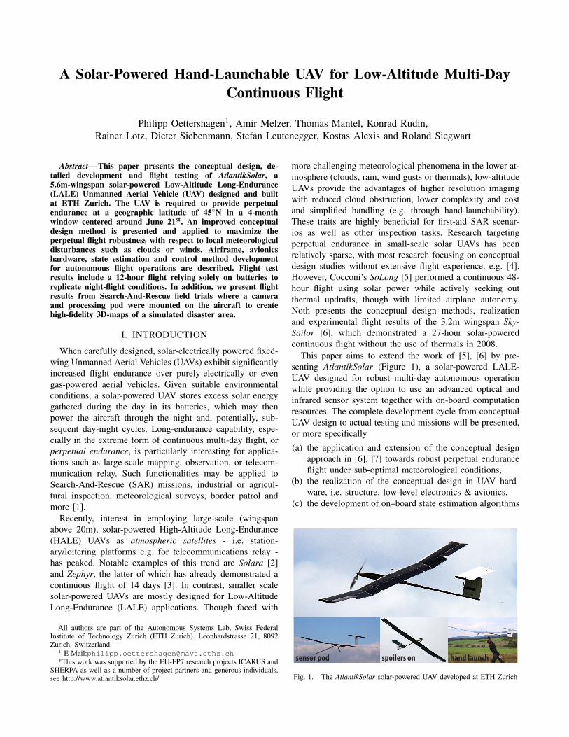
This paper aims to extend the work of [5], [6] by pre-senting AtlantikSolar (Figure 1), a solar-powered LALE-UAV designed for robust multi-day autonomous operationwhile providing the option to use an advanced optical andinfrared sensor system together with on-board computationresources. The complete development cycle from conceptualUAV design to actual testing and missions will be presented,or more specifically
(a) the application and extension of the conceptual designapproach in [6], [7] towards robust perpetual enduranceflight under sub-optimal meteorological conditions,
(b) the realization of the conceptual design in UAV hard-ware, i.e. structure, low-level electronics & avionics,
(c) the development of on–board state estimation algorithms
sensor pod spoilers on hand launch
Fig. 1. The AtlantikSolar solar-powered UAV developed at ETH Zurich
and flight control methods based on an Extended KalmanFilter (EKF) and PID control with non-linear guidanceand
(d) the discussion of flight test results including long-endurance flight (up to 12 hours) and mapping duringexemplary SAR missions.
II. CONCEPTUAL DESIGN METHODOLOGYThe conceptual design methodology for solar-powered
UAVs used in this paper relies on the work in [6], [7]. Itis extended to include uncertainty in local meteorologicalconditions such as clouds or winds.
A. System ModelThe general approach for perpetual endurance for LALE-
UAVs is to fly level at low altitude to be energy–efficient,while charging the batteries. When the batteries are fullycharged, the excess energy is used to climb and gain po-tential energy. To analyze flight performance the energyinput/output-balance under the assumption of level flight atlowest admissible altitude is modeled. The total requirednominal electric output power
Pnomout =
Plevel
ηprop+Pav +Ppld (1)
consists of the required electric propulsion power for level-flight Plevel
ηprop, where ηprop includes propeller, gearbox, motor,
and motor-controller efficiency, and the necessary avionicsand payload power Pav and Ppld . The UAV is assumed to flyat the airspeed of minimum aerodynamic level-flight power
Plevel =
CD
C32L
min
√2(mtotg)3
ρ(h)Awing. (2)
Here, mtot = mbat +mstruct +mprop +msm +mav +mpld is thetotal airplane mass, where structure, propulsion and solarmodule masses mstruct , mprop, msm are optimized and mav,mpld are given in Table I. The local earth gravity is desig-nated by g, Awing is the wing area, and ρ(h) is the altitudedependent air density. The airplane lift and drag coefficientsCL and CD are retrieved from 2-D airfoil simulations usingXFoil [8], with CD being combined with parasitic drag fromthe airplane fuselage and stabilizers and the induced drag
CD,ind =C2
Lπ · e0 ·λ
. (3)
Here, e0 ≈ 0.92 is the Oswald efficiency and λ the wingaspect ratio. On the input side, the nominal solar input power
Pnomsolar = I ·Asm ·ηsm ·ηmppt (4)
considers the solar module area Asm = fsm ·Awing with relativefill-factor fsm, module efficiency ηsm, and Maximum PowerPoint Tracker (MPPT) efficiency ηmppt . The solar radiationI = I(ϕ,h, t) is assumed to be a function of the geographicallatitude ϕ , the altitude h, and the current date and local timet, and is modeled as in [9]. While the batteries are not fullycharged (Ebat < Emax
bat ), the energy balance may be written asdEbat
dt = Psolar(ϕ,h, t)−Pprop−Pav−Ppld . (5)
5 10 15 20 25 30 35 40 45 50 550
200
400
Po
wer
[W]
0
500
Ene
rgy
[Wh
]
Psolar
[W]
Pout
[W]
Ebat
[Wh]texc
Ebat,max
tsr
tcm
teq
Time[h]
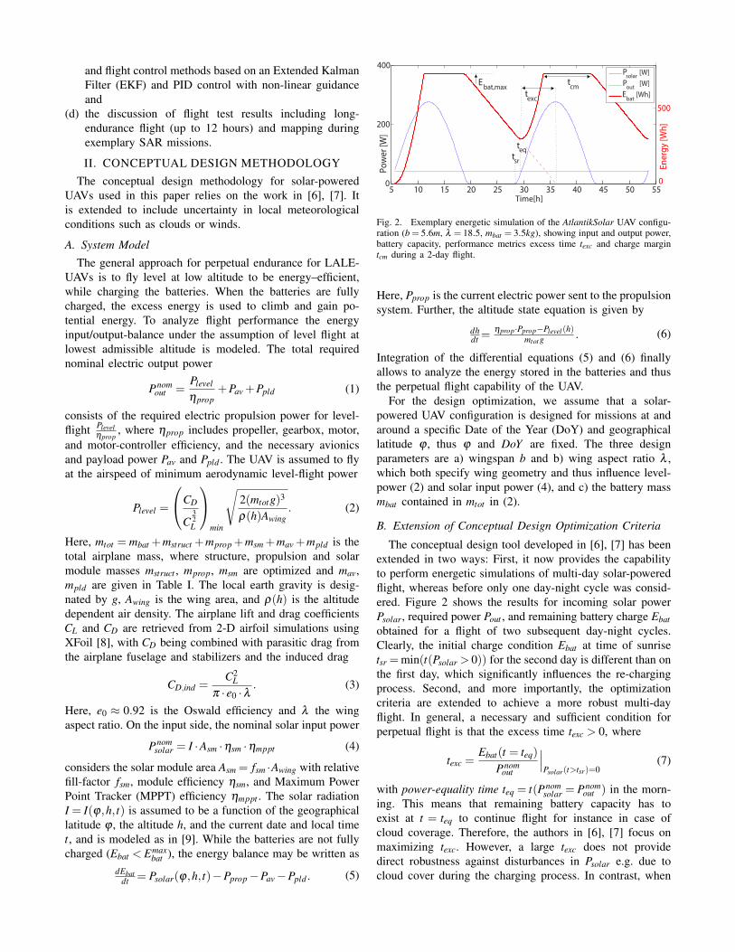
Fig. 2. Exemplary energetic simulation of the AtlantikSolar UAV configu-ration (b = 5.6m, λ = 18.5, mbat = 3.5kg), showing input and output power,battery capacity, performance metrics excess time texc and charge margintcm during a 2-day flight.
Here, Pprop is the current electric power sent to the propulsionsystem. Further, the altitude state equation is given by
dhdt =
ηprop·Pprop−Plevel(h)mtot g
. (6)
Integration of the differential equations (5) and (6) finallyallows to analyze the energy stored in the batteries and thusthe perpetual flight capability of the UAV.
For the design optimization, we assume that a solar-powered UAV configuration is designed for missions at andaround a specific Date of the Year (DoY) and geographicallatitude ϕ , thus ϕ and DoY are fixed. The three designparameters are a) wingspan b and b) wing aspect ratio λ ,which both specify wing geometry and thus influence level-power (2) and solar input power (4), and c) the battery massmbat contained in mtot in (2).
B. Extension of Conceptual Design Optimization Criteria
The conceptual design tool developed in [6], [7] has beenextended in two ways: First, it now provides the capabilityto perform energetic simulations of multi-day solar-poweredflight, whereas before only one day-night cycle was consid-ered. Figure 2 shows the results for incoming solar powerPsolar, required power Pout , and remaining battery charge Ebatobtained for a flight of two subsequent day-night cycles.Clearly, the initial charge condition Ebat at time of sunrisetsr =min(t(Psolar > 0)) for the second day is different than onthe first day, which significantly influences the re-chargingprocess. Second, and more importantly, the optimizationcriteria are extended to achieve a more robust multi-dayflight. In general, a necessary and sufficient condition forperpetual flight is that the excess time texc > 0, where
texc =Ebat(t = teq)
Pnomout
∣∣∣Psolar(t>tsr)=0
(7)
with power-equality time teq = t(Pnomsolar = Pnom
out ) in the morn-ing. This means that remaining battery capacity has toexist at t = teq to continue flight for instance in case ofcloud coverage. Therefore, the authors in [6], [7] focus onmaximizing texc. However, a large texc does not providedirect robustness against disturbances in Psolar e.g. due tocloud cover during the charging process. In contrast, when
optimizing purely for texc, the methodology in Sec. II-A willselect the largest battery size (due to the scaling of Plevel withmbat ) which can be fully charged under optimal conditions,but every reduction in Psolar will directly decrease texc dueto only partially charged batteries. Thus, we introduce thecharge margin tcm as the time margin between achieving thefull charge Ebat = E max
bat and restart of the discharge in theevening. In case of decreased solar power income, tcm > 0provides additional margin before a decrease in excess timeoccurs.
The overall approach for increasing robustness with re-spect to local power disturbances is thus to determine thelowest acceptable texc satisfying the UAV application require-ments, and then to optimize the configuration for tcm. Theexact procedure applied in this paper is:
1 Selection of nominal operating latitude ϕ , Day ofOperation DoY nom and the outermost days whereperpetual UAV endurance is required DoY min,max
2 Retrieval of the night durations tminnight , tmax
night from [9]for the range of DoY = [DoY min,DoY max]
3 The required excess time treqexc is now the sum of
• texc,DoY = t maxnight − t min
night• texc,clouds, to allow a margin for clouds in themorning or evening• texc,Plevel , to allow a margin for increasedpower consumption e.g. caused by downdraftsor uncertainties in estimating Plevel
4 Design analysis given the methodology inSection II-A for DoY (tnight = t min
night). Pre-selection ofthe subset S of configurations satisfying texc > treq
exc5 Allowance for a set of intermediate configurations
Si within S while taking UAV-specific constraintson b, λ , or mbat into account. Selection of the finalconfiguration S f from Si in order to obtain thelargest charge margin tcm
This conceptual design methodology is applied below. Analternative conceptual design approach utilizing a weightedversion of texc and tcm is proposed in [4].
C. Application of Conceptual Design Methodology
AtlantikSolar operates at a nominal latitude of ϕ = 45◦Nand shall provide perpetual endurance within a +/-2 monthwindow centered around DoY nom=June 21st (April 21st-August 21st). From [9], we find t min
night = 8.7h (June 21st),t maxnight = 10.5h (April 21st), and thus texc,DoY = 1.80h. We
choose texc,clouds = 3.0h to account for three hours of fullcloud coverage either on the evening or the morning andchoose texc,Plevel = 0.2 · tmax
night = 2.1h to cover increased powerconsumption due to modeling errors, downdrafts or head-winds. Using treq
exc = texc,DoY + texc,clouds+ texc,Plevel , we retrievetreqexc = 6.9h as the minimum required excess time for robust
perpetual flight at the given dates and locations.The design methodology tool of Section II-A is now
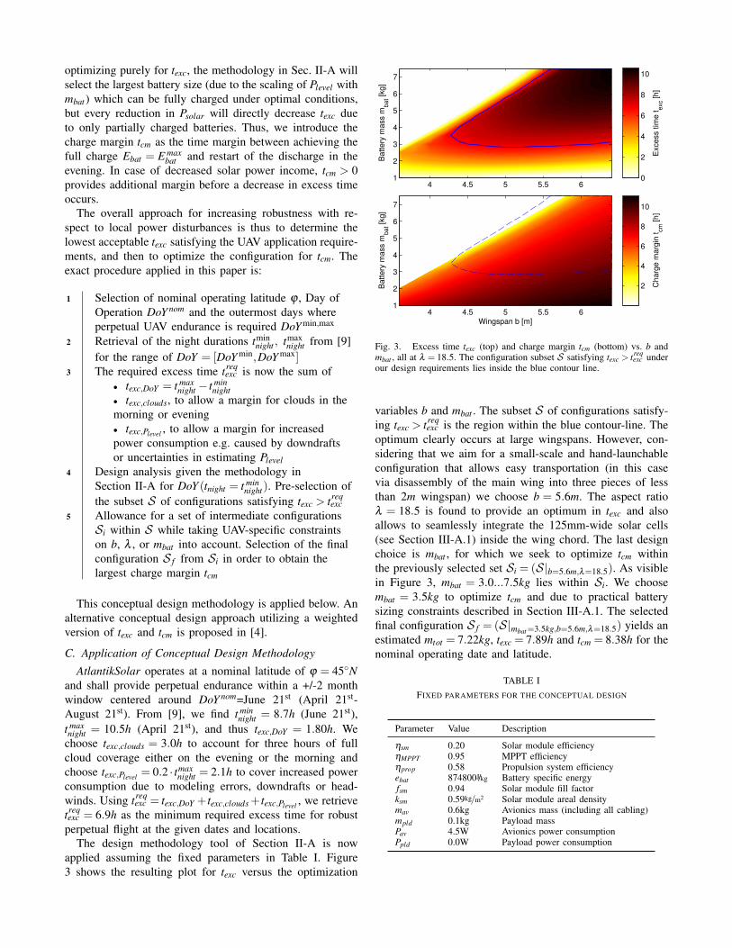
applied assuming the fixed parameters in Table I. Figure3 shows the resulting plot for texc versus the optimization
Ba
tte
ry m
ass m
ba
t [kg
]
4 4.5 5 5.5 61
2
3
4
5
6
7
Exce
ss t
ime
te
xc [
h]
0
2
4
6
8
10
Wingspan b [m]
Ba
tte
ry m
ass m
ba
t [kg
]
4 4.5 5 5.5 61
2
3
4
5
6
7
Ch
arg
e m
arg
in t
cm
[h
]
2
4
6
8
10
Fig. 3. Excess time texc (top) and charge margin tcm (bottom) vs. b andmbat , all at λ = 18.5. The configuration subset S satisfying texc > treq
exc underour design requirements lies inside the blue contour line.
variables b and mbat . The subset S of configurations satisfy-ing texc > treq
exc is the region within the blue contour-line. Theoptimum clearly occurs at large wingspans. However, con-sidering that we aim for a small-scale and hand-launchableconfiguration that allows easy transportation (in this casevia disassembly of the main wing into three pieces of lessthan 2m wingspan) we choose b = 5.6m. The aspect ratioλ = 18.5 is found to provide an optimum in texc and alsoallows to seamlessly integrate the 125mm-wide solar cells(see Section III-A.1) inside the wing chord. The last designchoice is mbat , for which we seek to optimize tcm withinthe previously selected set Si = (S |b=5.6m,λ=18.5). As visiblein Figure 3, mbat = 3.0...7.5kg lies within Si. We choosembat = 3.5kg to optimize tcm and due to practical batterysizing constraints described in Section III-A.1. The selectedfinal configuration S f = (S |mbat=3.5kg,b=5.6m,λ=18.5) yields anestimated mtot = 7.22kg, texc = 7.89h and tcm = 8.38h for thenominal operating date and latitude.
TABLE IFIXED PARAMETERS FOR THE CONCEPTUAL DESIGN
Parameter Value Description
ηsm 0.20 Solar module efficiencyηMPPT 0.95 MPPT efficiencyηprop 0.58 Propulsion system efficiencyebat 874800J/kg Battery specific energyfsm 0.94 Solar module fill factorksm 0.59kg/m2 Solar module areal densitymav 0.6kg Avionics mass (including all cabling)mpld 0.1kg Payload massPav 4.5W Avionics power consumptionPpld 0.0W Payload power consumption
Pou
t/Pou
t,nom
[−]
0.5 0.6 0.7 0.8 0.9 11
1.1
1.21.31.4
1.51.6
t exc
[h]
0
2
4
6
8Pin/Pin,nom [−]
Pou
t/Pou
t,nom
[−]
0.5 0.6 0.7 0.8 0.9 11
1.1
1.21.31.4
1.51.6
t exc
[h]
0
2
4
6
8
Psolar / Psolar,nom [−]
Pou
t/Pou
t,nom
[−]
0.5 0.6 0.7 0.8 0.9 11
1.1
1.21.31.4
1.51.6
t exc
[h]
0
2
4
6
8Pin/Pin,nom [−]
Pou
t/Pou
t,nom
[−]
0.5 0.6 0.7 0.8 0.9 11
1.1
1.21.31.4
1.51.6
t exc
[h]
0
2
4
6
8
b)
a) c)
d)
Psolar solar,nom [−]/ P
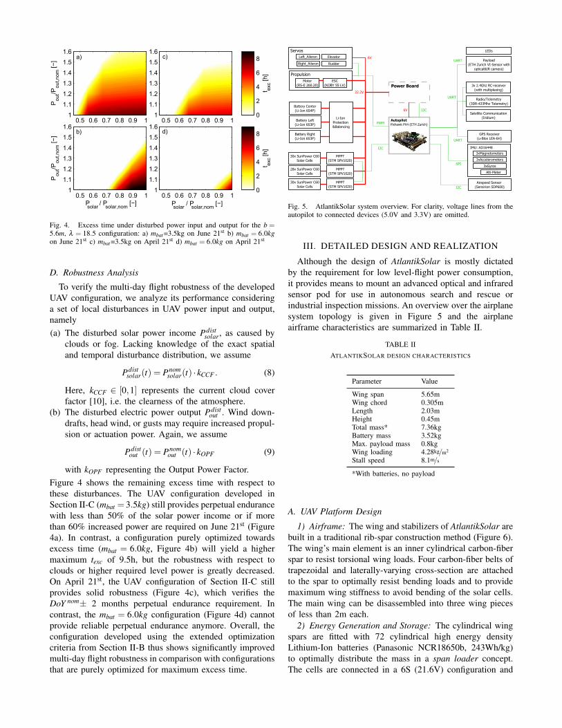
Fig. 4. Excess time under disturbed power input and output for the b =5.6m, λ = 18.5 configuration: a) mbat =3.5kg on June 21st b) mbat = 6.0kgon June 21st c) mbat =3.5kg on April 21st d) mbat = 6.0kg on April 21st
D. Robustness Analysis
To verify the multi-day flight robustness of the developedUAV configuration, we analyze its performance consideringa set of local disturbances in UAV power input and output,namely(a) The disturbed solar power income Pdist
solar, as caused byclouds or fog. Lacking knowledge of the exact spatialand temporal disturbance distribution, we assume
Pdistsolar(t) = Pnom
solar(t) · kCCF . (8)
Here, kCCF ∈ [0,1] represents the current cloud coverfactor [10], i.e. the clearness of the atmosphere.
(b) The disturbed electric power output Pdistout . Wind down-
drafts, head wind, or gusts may require increased propul-sion or actuation power. Again, we assume
Pdistout (t) = Pnom
out (t) · kOPF (9)
with kOPF representing the Output Power Factor.Figure 4 shows the remaining excess time with respect tothese disturbances. The UAV configuration developed inSection II-C (mbat = 3.5kg) still provides perpetual endurancewith less than 50% of the solar power income or if morethan 60% increased power are required on June 21st (Figure4a). In contrast, a configuration purely optimized towardsexcess time (mbat = 6.0kg, Figure 4b) will yield a highermaximum texc of 9.5h, but the robustness with respect toclouds or higher required level power is greatly decreased.On April 21st, the UAV configuration of Section II-C stillprovides solid robustness (Figure 4c), which verifies theDoY nom± 2 months perpetual endurance requirement. Incontrast, the mbat = 6.0kg configuration (Figure 4d) cannotprovide reliable perpetual endurance anymore. Overall, theconfiguration developed using the extended optimizationcriteria from Section II-B thus shows significantly improvedmulti-day flight robustness in comparison with configurationsthat are purely optimized for maximum excess time.
GPS Receiver(u-Blox LEA-6H)
Satellite Communication(Iridium)
3x 2.4Ghz RC-receiver(with multiplexing)
3xMagnetometers
3xAccelerometers
3xGyros
Airspeed Sensor (Sensirion SDP600)
Alti-Meter
Battery Center(Li-Ion 6S4P)
Battery Left(Li-Ion 6S3P)
Battery Right(Li-Ion 6S3P)
Motor(RS-E 260.20)
ESC(KOBY 55 LV)
Payload(ETH Zurich VI-Sensor with
optical&IR camera)
Radio/Telemetry(3DR-433Mhz Telemetry)
LEDs
IMU: AD16448
6V
Propulsion
Autopilot
Left_Aileron
Right_Aileron
Elevator
Rudder
Servos
30x SunPower C60Solar Cells
MPPT(STM SPV1020)
MPPT(STM SPV1020)
MPPT(STM SPV1020) I2C
Power Board
Li-Ion Protection &Balancing
28x SunPower C60Solar Cells
30x SunPower C60Solar Cells
6V I2C
22.2V
I2C
PWM
UART
SPI
UART
UART
Pixhawk PX4 (ETH Zurich)
Fig. 5. AtlantikSolar system overview. For clarity, voltage lines from theautopilot to connected devices (5.0V and 3.3V) are omitted.
III. DETAILED DESIGN AND REALIZATION
Although the design of AtlantikSolar is mostly dictatedby the requirement for low level-flight power consumption,it provides means to mount an advanced optical and infraredsensor pod for use in autonomous search and rescue orindustrial inspection missions. An overview over the airplanesystem topology is given in Figure 5 and the airplaneairframe characteristics are summarized in Table II.
TABLE IIATLANTIKSOLAR DESIGN CHARACTERISTICS
Parameter Value
Wing span 5.65mWing chord 0.305mLength 2.03mHeight 0.45mTotal mass* 7.36kgBattery mass 3.52kgMax. payload mass 0.8kgWing loading 4.28kg/m2
Stall speed 8.1m/s
*With batteries, no payload
A. UAV Platform Design
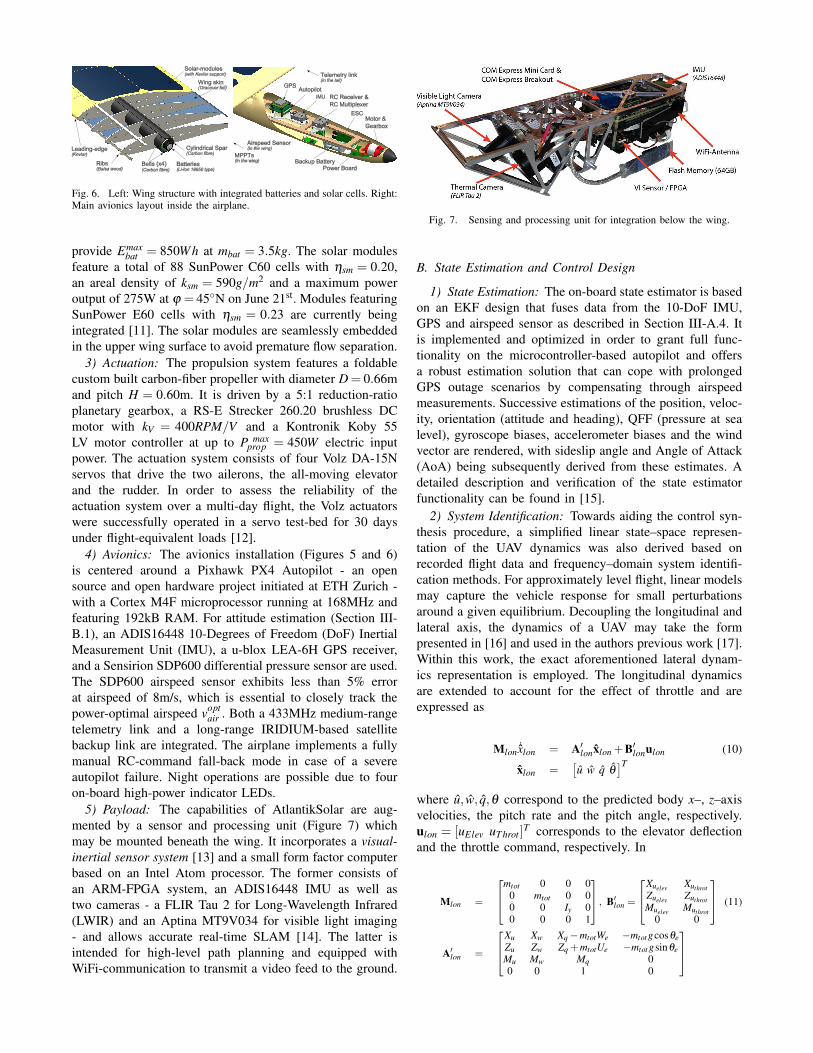
1) Airframe: The wing and stabilizers of AtlantikSolar arebuilt in a traditional rib-spar construction method (Figure 6).The wing’s main element is an inner cylindrical carbon-fiberspar to resist torsional wing loads. Four carbon-fiber belts oftrapezoidal and laterally-varying cross-section are attachedto the spar to optimally resist bending loads and to providemaximum wing stiffness to avoid bending of the solar cells.The main wing can be disassembled into three wing piecesof less than 2m each.
2) Energy Generation and Storage: The cylindrical wingspars are fitted with 72 cylindrical high energy densityLithium-Ion batteries (Panasonic NCR18650b, 243Wh/kg)to optimally distribute the mass in a span loader concept.The cells are connected in a 6S (21.6V) configuration and
IMU
GPSAutopilot
RC Receiver &
RC Multiplexer
Power Board
ESC
Backup Battery
Motor &
Gearbox
Airspeed Sensor(in the wing)
MPPTs(in the wing)
Telemetry link(in the tail)
Cylindrical Spar(Carbon fibre)
Belts (x4)(Carbon fibre)
Batteries(Li-Ion 18650 type)
Leading-edge(Kevlar)
Ribs(Balsa wood)
Solar-modules(with Kevlar support)
Wing skin(Oracover foil)
Fig. 6. Left: Wing structure with integrated batteries and solar cells. Right:Main avionics layout inside the airplane.
provide Emaxbat = 850Wh at mbat = 3.5kg. The solar modules
feature a total of 88 SunPower C60 cells with ηsm = 0.20,an areal density of ksm = 590g/m2 and a maximum poweroutput of 275W at ϕ = 45◦N on June 21st. Modules featuringSunPower E60 cells with ηsm = 0.23 are currently beingintegrated [11]. The solar modules are seamlessly embeddedin the upper wing surface to avoid premature flow separation.
3) Actuation: The propulsion system features a foldablecustom built carbon-fiber propeller with diameter D = 0.66mand pitch H = 0.60m. It is driven by a 5:1 reduction-ratioplanetary gearbox, a RS-E Strecker 260.20 brushless DCmotor with kV = 400RPM/V and a Kontronik Koby 55LV motor controller at up to P max
prop = 450W electric inputpower. The actuation system consists of four Volz DA-15Nservos that drive the two ailerons, the all-moving elevatorand the rudder. In order to assess the reliability of theactuation system over a multi-day flight, the Volz actuatorswere successfully operated in a servo test-bed for 30 daysunder flight-equivalent loads [12].
4) Avionics: The avionics installation (Figures 5 and 6)is centered around a Pixhawk PX4 Autopilot - an opensource and open hardware project initiated at ETH Zurich -with a Cortex M4F microprocessor running at 168MHz andfeaturing 192kB RAM. For attitude estimation (Section III-B.1), an ADIS16448 10-Degrees of Freedom (DoF) InertialMeasurement Unit (IMU), a u-blox LEA-6H GPS receiver,and a Sensirion SDP600 differential pressure sensor are used.The SDP600 airspeed sensor exhibits less than 5% errorat airspeed of 8m/s, which is essential to closely track thepower-optimal airspeed vopt
air . Both a 433MHz medium-rangetelemetry link and a long-range IRIDIUM-based satellitebackup link are integrated. The airplane implements a fullymanual RC-command fall-back mode in case of a severeautopilot failure. Night operations are possible due to fouron-board high-power indicator LEDs.
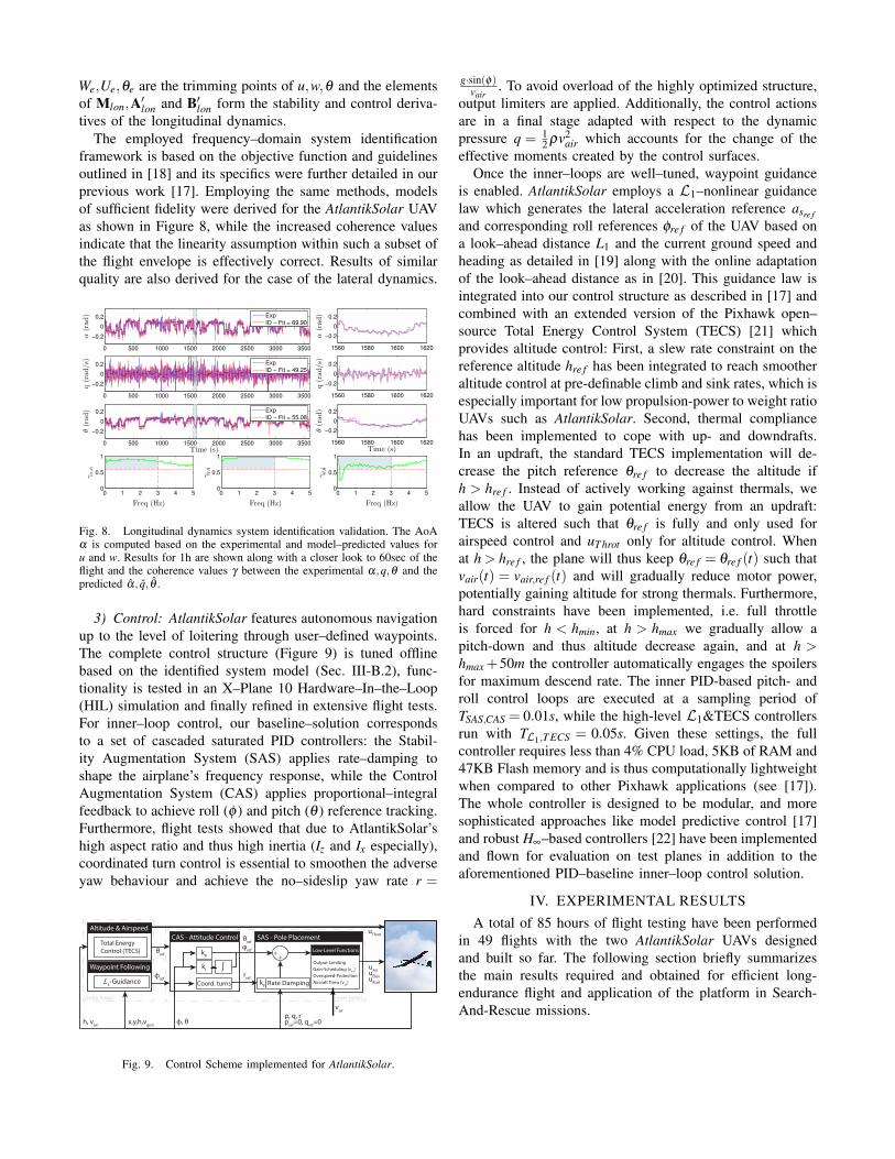
5) Payload: The capabilities of AtlantikSolar are aug-mented by a sensor and processing unit (Figure 7) whichmay be mounted beneath the wing. It incorporates a visual-inertial sensor system [13] and a small form factor computerbased on an Intel Atom processor. The former consists ofan ARM-FPGA system, an ADIS16448 IMU as well astwo cameras - a FLIR Tau 2 for Long-Wavelength Infrared(LWIR) and an Aptina MT9V034 for visible light imaging- and allows accurate real-time SLAM [14]. The latter isintended for high-level path planning and equipped withWiFi-communication to transmit a video feed to the ground.
Fig. 7. Sensing and processing unit for integration below the wing.
B. State Estimation and Control Design
1) State Estimation: The on-board state estimator is basedon an EKF design that fuses data from the 10-DoF IMU,GPS and airspeed sensor as described in Section III-A.4. Itis implemented and optimized in order to grant full func-tionality on the microcontroller-based autopilot and offersa robust estimation solution that can cope with prolongedGPS outage scenarios by compensating through airspeedmeasurements. Successive estimations of the position, veloc-ity, orientation (attitude and heading), QFF (pressure at sealevel), gyroscope biases, accelerometer biases and the windvector are rendered, with sideslip angle and Angle of Attack(AoA) being subsequently derived from these estimates. Adetailed description and verification of the state estimatorfunctionality can be found in [15].
2) System Identification: Towards aiding the control syn-thesis procedure, a simplified linear state–space represen-tation of the UAV dynamics was also derived based onrecorded flight data and frequency–domain system identifi-cation methods. For approximately level flight, linear modelsmay capture the vehicle response for small perturbationsaround a given equilibrium. Decoupling the longitudinal andlateral axis, the dynamics of a UAV may take the formpresented in [16] and used in the authors previous work [17].Within this work, the exact aforementioned lateral dynam-ics representation is employed. The longitudinal dynamicsare extended to account for the effect of throttle and areexpressed as
Mlon ˙xlon = A′lonxlon +B′lonulon (10)
xlon =[u w q θ
]Twhere u, w, q,θ correspond to the predicted body x–, z–axisvelocities, the pitch rate and the pitch angle, respectively.ulon = [uElev uT hrot ]
T corresponds to the elevator deflectionand the throttle command, respectively. In
Mlon =
mtot 0 0 00 mtot 0 00 0 Iy 00 0 0 1
, B′lon =
Xuelev XuthrotZuelev ZuthrotMuelev Muthrot
0 0
(11)
A′lon =
Xu Xw Xq−mtotWe −mtot gcosθeZu Zw Zq +mtotUe −mtot gsinθeMu Mw Mq 00 0 1 0
We,Ue,θe are the trimming points of u,w,θ and the elementsof Mlon,A′lon and B′lon form the stability and control deriva-tives of the longitudinal dynamics.
The employed frequency–domain system identificationframework is based on the objective function and guidelinesoutlined in [18] and its specifics were further detailed in ourprevious work [17]. Employing the same methods, modelsof sufficient fidelity were derived for the AtlantikSolar UAVas shown in Figure 8, while the increased coherence valuesindicate that the linearity assumption within such a subset ofthe flight envelope is effectively correct. Results of similarquality are also derived for the case of the lateral dynamics.
0 500 1000 1500 2000 2500 3000 3500
−0.2
0
0.2
α(rad)
Exp
ID − Fit = 69.90
0 500 1000 1500 2000 2500 3000 3500
−0.2
0
0.2
q(rad/s)
Exp
ID − Fit = 49.25
0 500 1000 1500 2000 2500 3000 3500
−0.2
0
0.2
θ(rad)
Time (s)
Exp
ID − Fit = 55.08
0 1 2 3 4 50
0.5
1
Freq (Hz)
γα,α
0 1 2 3 4 50
0.5
1
Freq (Hz)
γq,q
0 1 2 3 4 50
0.5
1
Freq (Hz)
γθ,θ
1560 1580 1600 1620
−0.2
0
0.2α(rad)
1560 1580 1600 1620
−0.2
0
0.2
q(rad/s)
1560 1580 1600 1620
−0.2
0
0.2
θ(rad)
Time (s)
Fig. 8. Longitudinal dynamics system identification validation. The AoAα is computed based on the experimental and model–predicted values foru and w. Results for 1h are shown along with a closer look to 60sec of theflight and the coherence values γ between the experimental α,q,θ and thepredicted α, q, θ .
3) Control: AtlantikSolar features autonomous navigationup to the level of loitering through user–defined waypoints.The complete control structure (Figure 9) is tuned offlinebased on the identified system model (Sec. III-B.2), func-tionality is tested in an X–Plane 10 Hardware–In–the–Loop(HIL) simulation and finally refined in extensive flight tests.For inner–loop control, our baseline–solution correspondsto a set of cascaded saturated PID controllers: the Stabil-ity Augmentation System (SAS) applies rate–damping toshape the airplane’s frequency response, while the ControlAugmentation System (CAS) applies proportional–integralfeedback to achieve roll (φ ) and pitch (θ ) reference tracking.Furthermore, flight tests showed that due to AtlantikSolar’shigh aspect ratio and thus high inertia (Iz and Ix especially),coordinated turn control is essential to smoothen the adverseyaw behaviour and achieve the no–sideslip yaw rate r =
ϕref
θref
kI
kP
Output-Limiting
Gain-Scheduling (vair
)
Overspeed-Protection
Aircraft Trims (vair
)
rref
Coord. turns
Inner loops
Rate Damping
p, q, rp
ref=0, q
ref=0ϕ, θx,y,h,v
gnd
vair
h, vair
CAS - Attitude Control
∫
kP
SAS - Pole Placement
Altitude & Airspeed
Waypoint Following
Total Energy Control (TECS)
ℒ1-Guidance
Outer loops
Low-Level Functions
uAiluElevuRud
uThrot
++
θref
φref
.
.
Fig. 9. Control Scheme implemented for AtlantikSolar.
g·sin(φ)vair
. To avoid overload of the highly optimized structure,output limiters are applied. Additionally, the control actionsare in a final stage adapted with respect to the dynamicpressure q = 1
2 ρv2air which accounts for the change of the
effective moments created by the control surfaces.Once the inner–loops are well–tuned, waypoint guidance
is enabled. AtlantikSolar employs a L1–nonlinear guidancelaw which generates the lateral acceleration reference asre f
and corresponding roll references φre f of the UAV based ona look–ahead distance L1 and the current ground speed andheading as detailed in [19] along with the online adaptationof the look–ahead distance as in [20]. This guidance law isintegrated into our control structure as described in [17] andcombined with an extended version of the Pixhawk open–source Total Energy Control System (TECS) [21] whichprovides altitude control: First, a slew rate constraint on thereference altitude hre f has been integrated to reach smootheraltitude control at pre-definable climb and sink rates, which isespecially important for low propulsion-power to weight ratioUAVs such as AtlantikSolar. Second, thermal compliancehas been implemented to cope with up- and downdrafts.In an updraft, the standard TECS implementation will de-crease the pitch reference θre f to decrease the altitude ifh > hre f . Instead of actively working against thermals, weallow the UAV to gain potential energy from an updraft:TECS is altered such that θre f is fully and only used forairspeed control and uT hrot only for altitude control. Whenat h > hre f , the plane will thus keep θre f = θre f (t) such thatvair(t) = vair,re f (t) and will gradually reduce motor power,potentially gaining altitude for strong thermals. Furthermore,hard constraints have been implemented, i.e. full throttleis forced for h < hmin, at h > hmax we gradually allow apitch-down and thus altitude decrease again, and at h >hmax +50m the controller automatically engages the spoilersfor maximum descend rate. The inner PID-based pitch- androll control loops are executed at a sampling period ofTSAS,CAS = 0.01s, while the high-level L1&TECS controllersrun with TL1,T ECS = 0.05s. Given these settings, the fullcontroller requires less than 4% CPU load, 5KB of RAM and47KB Flash memory and is thus computationally lightweightwhen compared to other Pixhawk applications (see [17]).The whole controller is designed to be modular, and moresophisticated approaches like model predictive control [17]and robust H∞–based controllers [22] have been implementedand flown for evaluation on test planes in addition to theaforementioned PID–baseline inner–loop control solution.
IV. EXPERIMENTAL RESULTS
A total of 85 hours of flight testing have been performedin 49 flights with the two AtlantikSolar UAVs designedand built so far. The following section briefly summarizesthe main results required and obtained for efficient long-endurance flight and application of the platform in Search-And-Rescue missions.
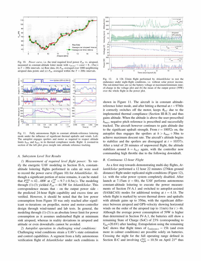
Fig. 10. Power curve, i.e. the total required level power Pout vs. airspeed,measured in constant-altitude loiter mode with vair,re f = const = 8...15m/sin T = 200s intervals. (a) Raw data, (b) Pout averaged over 1000 neighboringairspeed data points and (c) Pout averaged within the T = 200s intervals.
00.5
1
Sp
oil
ers
[ ]
Spoilers (OFF=0, ON=1)
−10
0
10
20
An
gle
s [°
]
φ φ
ref θ θref
0
10
20
Sp
ee
d [
m/s
]
vair
vair,ref
vGPS
600
700
800
900
Alt
itu
de
[m
]
h h
refh
maxh
minh
GPS
0.98 1 1.02 1.04 1.06 1.08 1.1 1.12
x 104
050
100
Th
rott
le [
%]
Time [s]
00.5
1
−10
0
10
20
5
10
15
20
600
700
800
900
0.998 1.002 1.006 1.009
x 104
−101
Time [s]
Fig. 11. Fully autonomous flight in constant altitude-reference loiteringmode under the influence of significant thermal updrafts and winds. Left:The autopilot engages spoilers and motor as required to respect altitudelimits hmin and hmax in its thermal compliance mode. Right: A zoomed-insection of the left plot gives insight into attitude reference tracking.
A. Subsystem Level Test Results
1) Measurement of required level flight power: To ver-ify the energetic UAV modeling in Section II-A, constant-altitude loitering flights performed in calm air were usedto record the power curve (Figure 10) for AtlantikSolar. Al-though a significant portion of noise remains, it can be statedthat Pmin
out ≈ 42...48W at voptair = 9.7±0.5m/s. The modeling
through (1)-(3) yielded Pout = 44.5W for AtlantikSolar. Thiscorrespondence means that - on the output power side -the predicted 24-hour flight capability and excess time areverified. However, it should be noted that the low powerconsumption from Figure 10 was only reached after signif-icant re-iterations on propeller, motor and motor-controllerdesign through wind-tunnel and lab tests. In general, themodeling through (1)-(3) is an absolute lower limit for powerconsumption as it assumes undisturbed flight at minimumsink airspeed, whereas in reality deviations in airspeed andattitude or even downdrafts cannot be avoided.
2) Autopilot operation in challenging wind conditions:Challenging wind conditions strain a UAV’s state estimationand control capabilities. A segment from a fully autonomousverification flight of AtlantikSolar under such conditions is
400
600
800
1000
Alt
itu
de
[m
]
h [m]
href
[m]
0
10
20
Ve
loci
ty [
m/s
]
Airspeed
GPS velocity
18
20
22
24
26
Vo
lta
ge
[V
]
VBat
max/min
0 2 4 6 8 10 120
200
400
Po
we
r [W
]
Time since launch [h]
Pout P
out
avrg
VBat
Fig. 12. A 12h 22min flight performed by AtlantikSolar to test theendurance under night-flight conditions, i.e. without solar power income.The red-dotted lines are (a) the battery voltage at maximum/minimum state-of-charge in the voltage plot and (b) the mean of the output power (59W)over the whole flight in the power plot.
shown in Figure 11. The aircraft is in constant altitude-reference loiter mode, and after hitting a thermal at t = 9760sit correctly switches off the motor, keeps θre f due to theimplemented thermal compliance (Section III-B.3) and thusgains altitude. When the altitude is above the user-prescribedhmax, negative pitch reference is prescribed and successfullytracked. The aircraft however continues to gain altitude dueto the significant updraft strength. From t = 10052s on, theautopilot thus engages the spoilers at h > hmax + 50m toachieve maximum descent rate. The aircraft’s altitude beginsto stabilize and the spoilers are disengaged at t = 10357s.After a total of 20 minutes of unpowered flight, the altitudestabilizes around h = hre f again, with the controller nowcommanding high throttle due to the following downdraft.
B. Continuous 12-hour Flight
As a first step towards demonstrating multi-day flights, At-lantikSolar performed a 12 hour 22 minutes (276km grounddistance) flight under replicated night-conditions (Figure 12),i.e. with the solar power system completely disabled. Afterlaunch at 7.15am (t = 0h), the UAV performs autonomousconstant-altitude loitering to execute the power measure-ments of Section IV-A.1 and switched to autopilot-assisted(SAS&CAS) modes for additional testing at t = 4.1h. Thewhole flight is marked by severe thermal down- and updraftswith altitude gains up to 350m, with the significant differ-ence between airspeed and GPS-velocity showing horizontalwinds on the order of the airspeed (up to 11m/s) for t > 4h.Although the average power consumption of 59W is higherthan determined in Section IV-A.1, the batteries still show aremaining State of Charge (SoC) of 23% (corresponding toVbat=20.6V) after landing. Extrapolation using the remainingSoC shows that flight times of tendurance = 15h (and evenmore in calmer conditions) are possible solely on batteries.Crossing the night for the full operating range defined inSection II-C and involving t max
night = 10.5h on April 21st thus
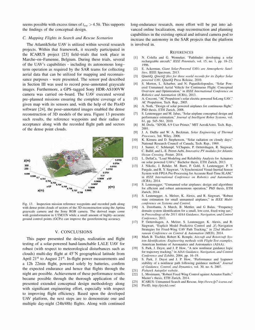
seems possible with excess times of texc > 4.5h. This supportsthe findings of the conceptual design.
C. Mapping Flights in Search and Rescue Scenarios
The AtlantikSolar UAV is utilized within several researchprojects. Within that framework, it recently participated inthe ICARUS project [23] field–trials that took place inMarche–en–Famenne, Belgium. During these trials, severalof the UAV’s capabilities - including its autonomous long–term operation as required by the SAR teams for collectingaerial data that can be utilized for mapping and reconnais-sance purposes - were presented. The sensor pod describedin Section III was used to record pose–annotated grayscaleimages. Furthermore, a GPS–tagged Sony HDR-AS100VWcamera was carried on–board. The UAV executed severalpre–planned missions ensuring the complete coverage of agiven map with its sensors and, with the help of the Pix4Dsoftware [24], the pose–annotated images enabled the densereconstruction of 3D models of the area. Figure 13 presentssuch results, the reference waypoints and their radius ofacceptance along with the recorded flight path and sectorsof the dense point clouds.
x(m)
z(m)
y(m)
300250
5.56955.5696
5.56975.5698
5.56995.575.5701
5.57025.5703
5.57045.5705
x105
x106
6.7086.707
6.7066.705
6.7046.703
6.7026.7016.7
6.6996.698
Fig. 13. Inspection mission reference waypoints and recorded path alongwith dense point clouds of sectors of the 3D reconstruction using the Aptinagrayscale camera and the Sony RGB camera. The derived maps comewith geoinformation in UTM31N while a small amount of highly–accurateground control points (GCPs) can improve the georeferencing accuracy.
V. CONCLUSIONS
This paper presented the design, realization and flighttesting of a solar-powered hand-launchable LALE UAV forrobust (with respect to meteorological disturbances such asclouds) multi-day flight at 45◦N geographical latitude fromApril 21st to August 21st. In-flight power measurements anda 12h 22min flight, powered solely by batteries, confirmthe expected endurance and hence that flights through thenight are possible. Achievement of these performance resultsbecame possible through the thorough application of thepresented extended conceptual design methodology alongwith significant engineering effort, especially with respectto improving flight efficiency. Based upon the developedUAV platform, the next steps are to demonstrate one andmultiple day-night (24h/48h) flights. Along with continued
long-endurance research, more effort will be put into ad-vanced online localization, map reconstruction and planningcapabilities in the existing optical and infrared camera pod toincrease the autonomy in the SAR projects that the platformis involved in.
REFERENCES
[1] N. Colella and G. Wenneker, “Pathfinder: developing a solarrechargeable aircraft,” IEEE Potentials, vol. 15, no. 1, pp. 18–23,1996.
[2] E. Ackerman, Giant Solar-Powered UAVs are Atmospheric Satel-lites, IEEE Spectrum, 2013.
[3] QinetiQ, QinetiQ files for three world records for its Zephyr Solarpowered UAV, QinetiQ Press Release, 2010.
[4] S. Morton, L. Scharber, and N. Papanikolopoulos, “Solar Pow-ered Unmanned Aerial Vehicle for Continuous Flight: ConceptualOverview and Optimization,” in IEEE International Conference onRobotics and Automation (ICRA), 2013.
[5] A. Cocconi, “AC Propulsion’s solar electric powered SoLong UAV,”AC Propulsion, Tech. Rep., 2005.
[6] A. Noth, “Design of solar powered airplanes for continuous flight,”PhD thesis, ETH Zurich, 2008.
[7] S. Leutenegger and M. Jabas, “Solar airplane conceptual design andperformance estimation,” Journal of Intelligent Robot Systems, vol.61, pp. 545–561, 2010.
[8] M. Drela, “XFOIL 6.9 User Primer,” MIT Aero&Astro, Tech. Rep.,2001.
[9] J. A. Duffie and W. A. Beckman, Solar Engineering of ThermalProcesses, 3rd. Wiley, 2006.
[10] K. Kimura and D. Stephenson, “Solar radiation on cloudy days,”National Research Council of Canada, Tech. Rep., 1969.
[11] J. Sunier, C. Schlumpf, V.Chapuis, P. Oettershagen, R. Siegwart,C. Ballif, and L.-E. Perret-Aebi, Innovative PV modules for AtlanticOcean Crossing, Poster, 2014.
[12] L. DellaCa, “Load Modeling and Reliability Analysis for Actuatorson solar powered UAVs,” Bachelor thesis, ETH Zurich, 2013.
[13] J. Nikolic, J. Rehder, M. Burri, P. Gohl, S. Leutenegger, P. T.Furgale, and R. Y. Siegwart, “A Synchronized Visual-Inertial SensorSystem with FPGA Pre-Processing for Accurate Real-Time SLAM,”in IEEE International Conference on Robotics and Automation(ICRA), 2014.
[14] S. Leutenegger, “Unmanned solar airplanes: design and algorithmsfor efficient and robust autonomous operation,” PhD thesis, ETHZurich, 2014.
[15] S. Leutenegger, A. Melzer, K. Alexis, and R. Siegwart, “Robuststate estimation for small unmanned airplanes,” in IEEE Multi-conference on Systems and Control.
[16] A. Dorobantu, A Murch, B. Mettler, and G Balas, “Frequencydomain system identification for a small, low-cost, fixed-wing uav,”in Proceedings of the 2011 AIAA Guidance, Navigation, and ControlConference, 2011.
[17] P. Oettershagen, A. Melzer, S. Leutenegger, K. Alexis, and R.Siegwart, “Explicit Model Predictive Control and L1-NavigationStrategies for Fixed-Wing UAV Path Tracking,” in 22nd Mediter-ranean Conference on Control & Automation (MED), 2014.
[18] Mark B. Tischler, Robert K. Remple, Aircraft and Rotorcraft Sys-tem Identification: Engineering methods with Flight-Test examples.American Institute of Aeronautics and Astronautics (AIAA).
[19] S. Park, J. Deyst, and J. P. How, “A new nonlinear guidance logicfor trajectory tracking,” in AIAA Guidance, Navigation, and ControlConference and Exhibit, 2004, pp. 16–19.
[20] S. Park, J. Deyst and J. P. How, “Performance and lyapunovstability of a nonlinear path following guidance method,” Journalof Guidance, Control, and Dynamics, vol. 30, no. 6, 2007.
[21] Pixhawk Autopilot website.[22] L. Mosimann, “Robust Fixed Wing Control against Actuator Faults,”
Master’s thesis, ETH Zurich, 2014.[23] ICARUS: Unmanned Search and Rescue, http://www.fp7-icarus.eu/.[24] Pix4D, http://pix4d.com/.