a special technique for determining the critical length of fibre pull-out from a cement matrix
TRANSCRIPT
JOURNAL OF MATERIALS SCIENCE LETTERS 7 (1988) 842-844
A special technique for determining the critical length of fibre pull-out from a cement matrix
Y O U J I A N G W A N G * , S T A N L E Y B A C K E R " , V ICTOR C. LI t *Department of Mechanical Engineering and ~Department of Civil Engineering, Massachusetts Institute of Technology, Cambridge, Massachusetts 02139, USA
The critical length of fibre pull-out (Lc), defined as the maximum embedded fibre length for a fibre to be pulled out from a matrix without rupture, is closely associated with the fracture behaviour of short fibre reinforced brittle matrix composites. In principle Lc can be determined from the fibre-matrix bonds strength, or vice versa. However, in practice the deter- mination of L~ or the fibre-matrix bond strength is extremely difficult or even impossible with conven- tional methods for certain fibre-matrix combinations in a recent paper on synthetic fibre reinforced concrete [1], a method for determining L~ was introduced which was particularly suitable for very thin flexible fibres in cement matrix composites. In order to achieve con-
sistent and reliable results, some special techniques for the test were required. In what follows we give a detailed description of this method with reference to tests reported earlier [1] in which an Lo of l l . 9 # m diameter aramid and 19.7#m diameter acrylic fibres was determined for a cement matrix. Lc for these fibres ranged from about 1 to 5 mm. For other fibre-matrix combinations the specific geometries, dimensions and procedures used in the example should be modified accordingly
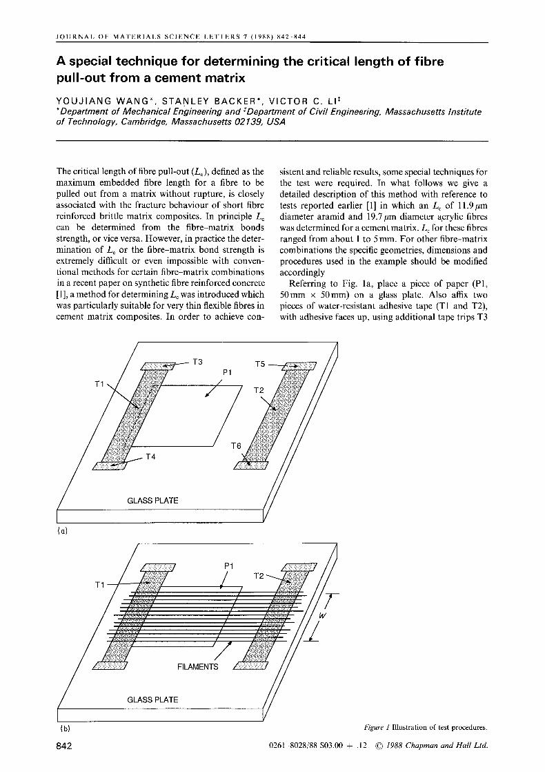
Referring to Fig. la, place a piece of paper (P1, 50mm x 50mm) on a glass plate. Also affix two pieces of water-resistant adhesive tape (T1 and T2), with adhesive faces up, using additional tape trips T3
T I \
T
GLASS
Y ' 3
(a)
(b)
842
Figure 1 Illustration of test procedures.
0261-8028/88 $03.00 + .12 © 1988 Chapman and Hall Ltd.
/
t7!
S PLAq
(d)
MARK EDGES OF P2 ON T7
p 2 ~ T 7 " :::i:
MARK EDGE OF T7 ON P2
CUT ALONG
III IIIII iiiiiiiiiiliitlIi !lililltii ............
:.r' iiiii;iiiii!i:i' !i!ilili' :b:~'~ b~b::.:::~2:
P4
THE FIBRE ARRAY
= Lmax =j
/ t
t I
i f
/
i"
t
CEMENT SLURRY
(c)
(f)
Figure 1 Continued.
to T6. Separate single filaments to be tested from a yarn (bundle) and lay them on tapes T1 and T2 as shown in Fig. lb. The spacing between filaments should be about 0.5 to 1 mm and the total width (W) is about 25 mm. Take another piece of tape (T7, same as T1) and press it on to tape T1, adhesive face to
adhesive face. Superimpose a piece of paper (P2, identical to P1) over P1 as illustrated in Fig. lc.
Mark the edges of paper P2 on tape T7 and also the edge of T7 on P2 (Fig. 1 d). Use a rule to press against paper P2 at the indicated angle and cut along its edge with a new surgical blade. The purpose of using paper
843

P3 / / . ~ B 1 T7 \ /
= B]
(h) P4 T/8' XB2 ~--~XB3 ( i i ' ~ I
~ ~ HARDENED MAIRIX
\ \ v
/ . . . . \ \ Y
(L o + L c)
t FIBRES RuP-rURED
- ~ ,," FIBRES l X ,' UNRUPTURED X
(j) = T7 (k)
L 0 + L C
f~L~ARKE D INE ON P2
Figure 1 Continued.
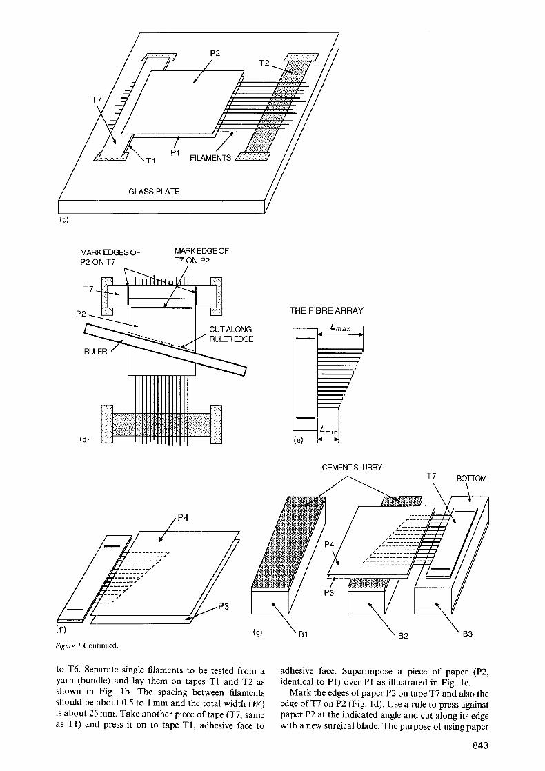
P1 and P2 is to fix the filament positions during cutting. After cutting, remove the "fibre array" from the glass plate by cutting the edgs of tapes T1 and T7. The fibre array obtained is shown in Fig. l e. The minimum fibre length (Lmi,) is about 15 mm and the maximum length (Lmax) about 30mm. As shown in Fig. l f, place the fibre array between two additional pieces of (P3 and P4, 40 mm x 40 ram).
The mould for the specimen consists of Plexiglas boxes with inner dimensions of 15mm(height)x 19.5mm(width) x 43mm(length). Three boxes (Bt, B2 and B3) are needed for each specimen. The inner surfaces of B1 and B2 should be coated with mould- releasing compound. Referring to Fig. lg, place boxes B1 and B2 open side up and B3 open side down on a table. The gap between B2 and B3 is about 10 mm. B2 and B3 can be fixed to the table with adhesive tape if necessary. Mix cement with water and fill boxes B1 and B2 with a cement slurry. Place the fibre array together with paper P3 and P4 on boxes B2 and B3 as indicated in Fig. lg. Quickly turn box B1 full of cement slurry over on top of box B2 as shown in Fig. 1 h. Use a piece of adhesive tape (T8) on each end to connect B 1 and B2 together. Pull paper P3 and P4 out as indicated while holding B1 and pressing T7 against B3. Vibrate the table slightly to condense the matrix, then cover the specimen with plastic film for setting and curing. After 1 day of curing separate boxes B1 and B2 from the matrix. If difficulties arise
in the separation, the shaded sides of boxes B1 and B2 can be cut offinstead with a blade heated by an electric stove (Fig. li). Measure L0, the fibre length between the matrix and the tape edge of T7. Put the specimen back to complete the curing.
The pull-out of the fibre array can be performed on a testing machine using frictional jaws to hold the tape end of the fibre array. After the fibre array is pulled out, measure the length X which is the distance between the longest unruptured fibre and the marked line on tape T7, as illustrated in Fig. lj. The maximum length of unruptured fibres is L0 4- Lc. However, this
!
length is often difficult to measure directly. Instead, L 0 + Lc is measured on paper P2 as shown in Fig. lk. Finally, L~ is obtained by subtracting L0 (Fig. li) from Lo+ Lo.
A final note for this method is that, during the whole process, precautions should be taken not to bend the fibres to high curvatures, especially for brittle fibres like aramids. This method is not recommended for extremely brittle fibres such as carbon fibres.
R e f e r e n c e I. Y. WANG, S. BACKER and V. C. LI, J. Mater. Sci. 22
(1987) 4281.
Received 5 January and accepted 2 March 1988
844