a standard driven software architecture for fully
TRANSCRIPT

A Standard Driven Software Architecture for Fully Autonomous Vehicles
Alex Serban1,2 Erik Poll 1 Joost Visser1,2
1 Radboud UniversityNijmegen, The Netherlands
E-mail: {a.serban, erikpoll}@cs.ru.nl2 Software Improvement GroupAmsterdam, The Netherlands
E-mail: {a.serban, j.visser}@sig.eu
Abstract
The development of self driving cars is often regarded as adding a layer of intelligence on top of classicvehicle platforms. However, the amount of software needed to reach autonomy will exceed the softwaredeployed for operation of normal vehicles. As complexity increases, the demand for proper structurealso increases. Moreover, the shift from open, deterministic components to more opaque, probabilisticsoftware components raises new challenges for system designers. In this paper we introduce a functionalsoftware architecture for fully autonomous vehicles aimed to standardize and ease the development pro-cess. Existing literature presents past experiments with autonomous driving or implementations specificto limited domains (e.g. winning a competition). The architectural solutions are often an after-math ofbuilding or evolving an autonomous vehicle and not the result of a clear software development life-cycle.A major issue of this approach is that requirements can not be traced with respect to functional com-ponents and several components group most functionality. Therefore, it is often difficult to adopt theproposals. In this paper we take a prescriptive approach starting with requirements from a widely adoptedautomotive standard. We follow a clear software engineering process, specific to the automotive indus-try. During the design process, we make extensive use of robotic architectures – which seem to be oftenignored by automotive software engineers – to support standard driven requirements.
Keywords: Intelligent vehicles, Autonomous vehicles, Robotics, Software architecture
1. Introduction
Autonomous driving is no longer a lab experiment.As manufacturers compete to raise the level of ve-hicle automation, cars become highly complex sys-tems. Driving task automation is often regarded asadding a layer of cognitive intelligence on top ofbasic vehicle platforms 1. While traditional me-chanical components become a commodity 2 andplanning algorithms become responsible for critical
decisions, software emerges as the lead innovationdriver. Recent trends forecast an increase in trafficsafety and efficiency by minimising human involve-ment and error . The transfer of total control fromhumans to machines is classified by the Society ofAutomotive Engineers (SAE) as a stepwise processon a scale from 0 to 5, where 0 involves no automa-tion and 5 means full-time performance by an auto-mated driving system of all driving aspects, underall roadway and environmental conditions 3. Since

A.C. Serban, E. Poll, J. Visser / Standard Driven Software Architecture
the amount of software grows, there is a need to useadvanced software engineering methods and tools tohandle its complexity, size and criticality. Softwaresystems are difficult to understand because of theirnon-linear nature - a one bit error can bring an entiresystem down, or a much larger error may do noth-ing. Moreover, many errors come from design flawsor requirements (miss-) specifications 4.
Basic vehicles already run large amounts of soft-ware with tight constraints concerning real-time pro-cessing, failure rate, maintainability and safety. Inorder to avoid design flaws or an unbalanced rep-resentation of requirements in the final product, thesoftware’s evolution towards autonomy must be wellmanaged. Since adding cognitive intelligence to ve-hicles leads to new software components deployedon existing platforms, a clear mapping betweenfunctional goals and software components is needed.
Software architecture was introduced as a meansto manage complexity in software systems and helpassess functional and non-functional attributes, be-fore the build phase. A good architecture is knownto help ensure that a system satisfies key require-ments in areas such as functional suitability, perfor-mance, reliability or interoperability 5.
The goal of this paper is to design a functionalsoftware architecture for fully autonomous vehicles.Existing literature takes a descriptive approach andpresents past experiments with autonomous drivingor implementations specific to limited domains (e.g.winning a competition). The architectural solutionsare therefore an after-math of building or evolvingan autonomous vehicle and not the result of a clearsoftware development life-cycle. A major issue ofthis approach is that requirements can not be tracedwith respect to functional components and severalcomponents group most functionality. Therefore,without inside knowledge, it is often not straight for-ward to adopt the proposals.
In this paper we take a prescriptive approachdriven by standard requirements. We use require-ments from the SAE J3016 standard, which definesmultiple levels of driving automation and includesfunctional definitions for each level. The goal ofSAE J3016 is to provide a complete taxonomy fordriving automation features and the underlying prin-
ciples used to evolve from none to full driving au-tomation. At the moment of writing this paper, it isthe only standard recommended practice for build-ing autonomous vehicles. We provide an extensivediscussion on the design decisions in the form oftrade-off analysis, which naturally leads to a bodyof easily accessible distilled knowledge. The currentproposal is an extension of our prior work 6.
The term functional architecture is used analo-gous to the term functional concept described in theISO 26262 automotive standard 7, 1: a specificationof intended functions and necessary interactions inorder to achieve desired behaviours. Moreover, it isequivalent to functional views in software architec-ture descriptions; which provide the architects withthe possibility to cluster functions and distributethem to the right teams to develop and to reasonabout them 4. Functional architecture design corre-sponds to the second step in the V-model 7, 8, a soft-ware development life cycle imposed by the manda-tory compliance to ISO 26262 automotive standard.
We follow the methodology described byWieringa 9 as the design cycle; a subset of the en-gineering cycle which precedes the solution imple-mentation and implementation evaluation. The de-sign cycle includes designing and validating a solu-tion for given requirements.
The rest of the paper is organised as follows.In Section 2 we introduce background information.In Section 3 we infer the requirements from theSAE J3016 standard. In Section 4 we present thereasoning process that lead to a solution domain.The functional components are introduced in Sec-tion 5, followed by component interaction patternsin Section 6 and a general trade-off analysis in Sec-tion 7. A discussion follows in Section 8. In Section9 we compare the proposal with related work andconclude with future research in Section 10.
2. Background
The development of automotive systems is dis-tributed between vehicle manufacturers, calledOriginal Equipment Manufacturers (OEM), andvarious component suppliers - leading to a dis-tributed software development life cycle where the

A.C. Serban, E. Poll, J. Visser / Standard Driven Software Architecture
OEM play the role of technology integrators. Thisdevelopment process allows OEM to delegate re-sponsibility for development, standardisation andcertification to their component suppliers. The samedistributed paradigm preserves, at the moment, forcomponent distribution and deployment inside a ve-hicle; where no central exists.
Instead, embedded systems called ElectronicControl Units (ECU) are deployed on vehicles inorder to enforce digital control of functional as-pects such as steering or brakes. Many features re-quire interactions and communications across sev-eral ECUs. For example, cruise control needs tocommand both the breaking and the steering systembased on the presence of other traffic participants. Inorder to increase component reuse across systems,manufacturers and vendors developed a numberof standardised communication buses (e.g. CAN,FlexRay) and software technology platforms (AU-TOSAR) that ease communication and deploymentbetween distributed components. We are herebyconcerned with designing functional software com-ponents which are deployed on ECUs and are re-quired to exchange information over one or manycommunication buses. Standardised interfaces (suchas the ones defined in AUTOSAR) help ease thedevelopment and communication between softwarecomponents, however, they do not have a big impacton their core functionality.
As mentioned in Section 1, SAE J3016 is astandard that defines multiple levels of automation,sketching an incremental evolution from no automa-tion to fully autonomous vehicles. The purpose ofthe standard is to be descriptive and broad about thisevolution, but it does not provide strict requirementsfor it. However, at the moment, it is the most com-prehensive. widely adopted, document that drivesthis evolution. Given its wide adoption, we use it asa baseline for our approach: vehicles should satisfyat least the functions described by this standard inorder to qualify for automation. With the goal ofunderstanding the vehicle automation process, wefirst introduce the most important terms as definedby SAE J3016 3:
• Dynamic Driving Task (DDT) - real-time opera-tional and tactical functions required to operate avehicle, excluding strategic functions such as tripscheduling or route planning. DDT is analogousto driving a car on a predefined route and includesactuator control (e.g. steering or braking) and tac-tical planning such as generating and followinga trajectory, keeping the vehicle within the lanes,maintaining distance from other vehicles, etc.
• Driving automation system - hardware and soft-ware systems collectively capable of performingsome parts or all of the DDT on a sustained ba-sis. Driving automation systems are usually com-posed of design-specific functionality called fea-tures (e.g. automated parking, lane keep assis-tance, etc.). The interplay between hardware andsoftware was described earlier. We are currentlyinterested in the interplay between software com-ponents in order to design driving automation sys-tems capable to achieve full autonomy.
• Operational Design Domains (ODD) - the spe-cific conditions under which a given driving au-tomation system or feature is designed to function.Defining an operational domain is an importanttask during the design phase, as the requirementschange in relation to it. For example, a vehiclewhich should operate in sunny weather in a lim-ited area of a city has different requirements thana vehicle which should operate in winter condi-tions, on mountain roads. As will be discussedlater, full autonomy requires a vehicle to operatewithout intervention in all weather and traffic con-ditions.
• DDT fall-back - the response by the user or by anAutomated Driving System (ADS) to either per-form the DDT task or achieve a safety state afteroccurrence of a DDT performance-relevant sys-tem failure or upon leaving the designated ODD.
• DDT fall-back-ready user - the user of a vehi-cle equipped with an engaged ADS feature whois able to operate the vehicle and is receptive toADS-issued requests to intervene and to performany if not all of the DDT tasks during a systemfailure or when an automated vehicle requests it.
• DDT feature - a design-specific functionality at aspecific level of driving automation with a partic-

A.C. Serban, E. Poll, J. Visser / Standard Driven Software Architecture
ular ODD. A feature can be seen as a specifichardware or software component that is performsa driving automation task in a predefined domain.We may think of lane assistance in sunny weatheras a DDT feature.
Besides hardware constraints, full vehicle automa-tion involves the automation of the DDT in all ODD,by developing a driving automation system. Re-cursively, driving automation systems are composedof design-specific features. In this sense, completevehicle automation is seen as developing, deploy-ing and orchestrating enough DDT features in orderto satisfy all conditions (ODDs) in which a humandriver can operate a vehicle (safely).
Fig. 1. SAE J3016 levels of driving automation.
The SAE classification of driving automation foron-road vehicles, showcased in Figure 1, is meantto clarify the role of a human driver, if any, duringvehicle operation. The first discriminant conditionis the environmental monitoring agent. In the caseof no automation up to partial automation (levels 0-2), the environment is monitored by a human driver,while for higher degrees of automation (levels 3-5),the vehicle becomes responsible for environmentalmonitoring.
Another discriminant criteria is the responsibil-ity for DDT fall-back mechanisms. Intelligent driv-
ing automation systems (levels 4-5) embed the re-sponsibility for automation fall-back constrained ornot by operational domains, while for low levels ofautomation (levels 0-3) a human driver is fully re-sponsible.
According to SAE:
• If the driving automation system performs the lon-gitudinal and/or lateral vehicle control, while thedriver is expected to complete the DDT, the divi-sion of roles corresponds to levels 1 and 2.
• If the driving automation system performs the en-tire DDT, but a DDT fall-back ready user is ex-pected to take over when a system failure occurs,then the division of roles corresponds to level 3.
• If a driving automation system can perform theentire DDT and fall-back within a prescribedODD or in all driver-manageable driving situation(unlimited ODD), then the division of roles corre-sponds to levels 4 and 5.
3. Requirements Inference
The process of functional architecture design startsby developing a list of functional components andtheir dependencies 4. Towards this end, SAE J3016defines three classes of components:
• Operational - basic vehicle control,• Tactical - planning and execution for event or ob-
ject avoidance and expedited route following, and• Strategic - destination and general route planning.
Each class of components has an incremental rolein a hierarchical control structure which starts fromlow level control, through the operational class andfinishes with a high level overview through thestrategic class of components. In between, the tac-tical components handle trajectory planning and re-sponse to traffic events. This hierarchical view uponincreasing the level of vehicle automation is an im-portant decision driver in architecture design.
Later, the SAE definition for DDT specifies, foreach class, the functionality that must be automatedin order to reach full autonomy (level 5):
• Lateral vehicle motion control via steering (oper-ational).
A.C. Serban, E. Poll, J. Visser / Standard Driven Software Architecture
• Longitudinal vehicle control via acceleration anddeceleration (operational).
• Monitoring of the driving environment via ob-ject and event detection, recognition, classifica-tion and response preparation (operational andtactical).
• Object and event response execution (operationaland tactical).
• Manoeuvre planning (tactical).• Enhanced conspicuity via lighting, signalling and
gesturing, etc. (tactical).
Moreover, an level 5 vehicle must ensure DDT fall-back and must implement strategic functions, notspecified in the DDT definition. The latter consistsof destination planning between two points providedby a human user or received from an operationalcenter.
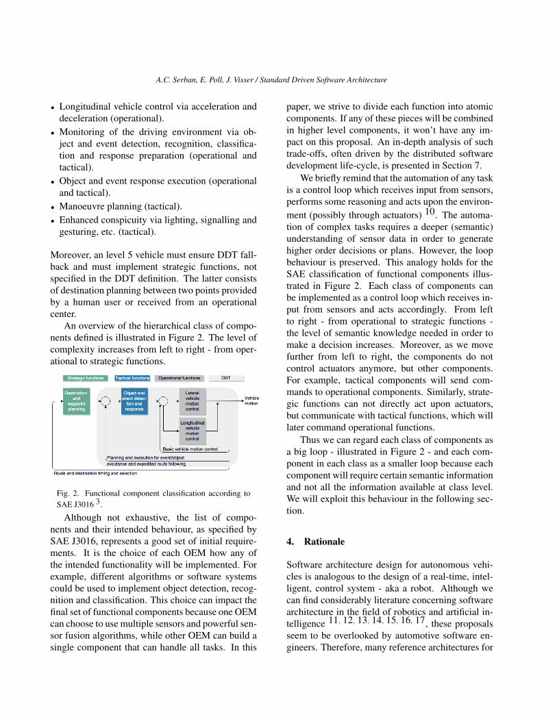
An overview of the hierarchical class of compo-nents defined is illustrated in Figure 2. The level ofcomplexity increases from left to right - from oper-ational to strategic functions.
Fig. 2. Functional component classification according toSAE J3016 3.
Although not exhaustive, the list of compo-nents and their intended behaviour, as specified bySAE J3016, represents a good set of initial require-ments. It is the choice of each OEM how any ofthe intended functionality will be implemented. Forexample, different algorithms or software systemscould be used to implement object detection, recog-nition and classification. This choice can impact thefinal set of functional components because one OEMcan choose to use multiple sensors and powerful sen-sor fusion algorithms, while other OEM can build asingle component that can handle all tasks. In this
paper, we strive to divide each function into atomiccomponents. If any of these pieces will be combinedin higher level components, it won’t have any im-pact on this proposal. An in-depth analysis of suchtrade-offs, often driven by the distributed softwaredevelopment life-cycle, is presented in Section 7.
We briefly remind that the automation of any taskis a control loop which receives input from sensors,performs some reasoning and acts upon the environ-ment (possibly through actuators) 10. The automa-tion of complex tasks requires a deeper (semantic)understanding of sensor data in order to generatehigher order decisions or plans. However, the loopbehaviour is preserved. This analogy holds for theSAE classification of functional components illus-trated in Figure 2. Each class of components canbe implemented as a control loop which receives in-put from sensors and acts accordingly. From leftto right - from operational to strategic functions -the level of semantic knowledge needed in order tomake a decision increases. Moreover, as we movefurther from left to right, the components do notcontrol actuators anymore, but other components.For example, tactical components will send com-mands to operational components. Similarly, strate-gic functions can not directly act upon actuators,but communicate with tactical functions, which willlater command operational functions.
Thus we can regard each class of components asa big loop - illustrated in Figure 2 - and each com-ponent in each class as a smaller loop because eachcomponent will require certain semantic informationand not all the information available at class level.We will exploit this behaviour in the following sec-tion.
4. Rationale
Software architecture design for autonomous vehi-cles is analogous to the design of a real-time, intel-ligent, control system - aka a robot. Although wecan find considerably literature concerning softwarearchitecture in the field of robotics and artificial in-telligence 11, 12, 13, 14, 15, 16, 17, these proposalsseem to be overlooked by automotive software en-gineers. Therefore, many reference architectures for

A.C. Serban, E. Poll, J. Visser / Standard Driven Software Architecture
autonomous vehicles miss developments and trade-offs explored in the field of robotics - as we willshall see in Section 9. We aim to bridge this gapin this section, by discussing the most important de-velopments in the field of robotics and select the bestchoices for the automotive domain.
For a long time, the dominant view in theAI community was that a control system for au-tonomous robots should be composed of three func-tional elements: a sensing system, a planning sys-tem and an execution system 18. This view led tothe ubiquitous sense-plan-act (SPA) paradigm. Forplanning, a system typically maintains an internalstate representation, which allows it to position itselfin the environment and plan next actions. Becausethis model has to be up-to-date and accurately reflectthe environment in which a robot operates, it mightrequire a lot of information. As the operational envi-ronment becomes more complex, the complexity ofthe internal representation also increases, increasingthe time needed to plan the next steps. Therefore, infast changing environments, new plans may be obso-lete before they are deployed. Moreover, unexpectedoutcomes from the execution of a plan stem maycause the next plan steps to be executed in an ap-propriate context and lead to unexpected outcomes.
One question that naturally stood up from theseshortcomings is ”how important is the internal statemodelling?”. In order to answer this question,several definitions meant to achieve similar goalswere proposed. Maes 11 first distinguishes betweenbehaviour and knowledge based systems - whereknowledge-based systems maintain an internal stateof the environment, while behaviour-based systemsdo not 11. Similarly, the literature distinguishes be-tween deliberative and reactive systems, where de-liberative systems reason upon an internal represen-tation of the environment and reactive system ful-fil goals through reflexive reactions to environmentchanges 13, 14, 15, 16. Reactive or behaviour basedsystems are able to react faster to a changing envi-ronment, but reason less about it.
We find both definitions to answer the samequestions - ”how will a system plan its decisions?”Through reasoning on complex semantic informa-tion extracted from its sensors or by simple reactions
to simple inputs? Deciding on this is an initial trade-off between speed of computation and the amount ofenvironmental understanding a system can have.
When considering the development of au-tonomous vehicles through these lenses, we can seethat vehicles require both reactive and deliberativecomponents. Maintaining a pre-defined trajectoryand distance from the objects around a vehicle is anexample of a reactive system, which should oper-ate with high frequency and be as fast as possiblein order to overcome any environmental change. Inthis case, maintaining a complex representation ofthe surrounding environment is futile.
However, a decision making mechanism respon-sible, for example, to overtake the vehicle in front isan example of a deliberative system. In this casemaintaining a complex world model can help thesystem to take a better decision.
For example, one can not only judge the dis-tances to the surrounding objects, but also the rel-evance of the decision in achieving the goal. Is itworth to overtake the car in front if the vehicle mustturn right in a relatively short distance after the over-take? In order to answer this question a complexworld model that must combine semantic informa-tion about the overall goal, future states and nearbyobjects is needed. Processing this amount of infor-mation will naturally take a longer time. However,since the result can only impact the passengers com-fort (assuming that driving behind a slow car for along time is un-comfortable) the system can assumethis processing time.
Gat and Bonnasso 13 first debate the role of in-ternal state and establish a balance between reac-tive and deliberative components inside a system. Intheir proposal, the functional components are clas-sified based on their memory and knowledge aboutthe internal state in: no knowledge, knowledge ofthe past, or knowledge of the future - thus resultingin three layers of functional components. However,their model does not specify how, or if, the knowl-edge can be shared between the layers. Moreover, itis not clear how and if any components incorporateknowledge about past, future and other static data.
A better proposal, that bridges the gap betweenreactive and deliberative components, is the NIST
A.C. Serban, E. Poll, J. Visser / Standard Driven Software Architecture
Real Time Control Systems (RCS) reference archi-tecture introduced by Albus 12. This architecturedoes not separate components based on memory, butbuilds a hierarchy based on semantical knowledge.
Thus, components lower in the hierarchy havelimited semantic understanding and can generateinputs for higher components, deepening their se-mantic knowledge and understanding. Moreover,RCS has no temporal limitations for a component’sknowledge. One can hold static or dynamic infor-mation about past, present or future. Although allcomponents maintain a wold model, this can be assimple as reference values, to which the input mustbe compared.
We find this proposal a good fit for automotiverequirements and for the functional classificationpresented in Section 3 because it allows a balancedrepresentation of reactive and deliberative compo-nents and it allows hierarchical semantic process-ing - one of the requirements given by the classi-fication of functional components proposed earlier.Further on, we introduce more details about it andillustrate it in Figure 3.
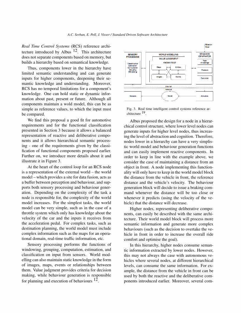
At the heart of the control loop for an RCS nodeis a representation of the external world – the worldmodel – which provides a site for data fusion, acts asa buffer between perception and behaviour, and sup-ports both sensory processing and behaviour gener-ation. Depending on the complexity of the task anode is responsible for, the complexity of the worldmodel increases. For the simplest tasks, the worldmodel can be very simple, such as in the case of athrottle system which only has knowledge about thevelocity of the car and the inputs it receives fromthe acceleration pedal. For complex tasks, such asdestination planning, the world model must includecomplex information such as the maps for an opera-tional domain, real-time traffic information, etc.
Sensory processing performs the functions ofwindowing, grouping, computation, estimation, andclassification on input from sensors. World mod-elling can also maintain static knowledge in the formof images, maps, events or relationships betweenthem. Value judgment provides criteria for decisionmaking, while behaviour generation is responsiblefor planning and execution of behaviours 12.
Fig. 3. Real time intelligent control systems reference ar-chitecture 19.
Albus proposed the design for a node in a hierar-chical control structure, where lower level nodes cangenerate inputs for higher level nodes, thus increas-ing the level of abstraction and cognition. Therefore,nodes lower in a hierarchy can have a very simplis-tic world model and behaviour generation functionsand can easily implement reactive components. Inorder to keep in line with the example above, weconsider the case of maintaining a distance from anobject in front. A node implementing this function-ality will only have to keep in the world model blockthe distance from the vehicle in front, the referencedistance and the vehicle’s velocity. The behaviourgeneration block will decide to issue a braking com-mand whenever the distance will be too close orwhenever it predicts (using the velocity of the ve-hicle) that the distance will decrease.
Higher nodes, representing deliberative compo-nents, can easily be described with the same archi-tecture. Their world model block will process moresemantic information and generate more complexbehaviours (such as the decision to overtake the ve-hicle in front in order to increase the overall ridecomfort and optimise the goal).
In this hierarchy, higher nodes consume seman-tic information extracted by lower nodes. However,this may not always the case with autonomous ve-hicles where several nodes, at different hierarchicallevels, can consume the same information. For ex-ample, the distance from the vehicle in front can beused by both the reactive and the deliberative com-ponents introduced earlier. Moreover, several com-
A.C. Serban, E. Poll, J. Visser / Standard Driven Software Architecture
ponents at the same hierarchical layer can interact,as a sequential process.
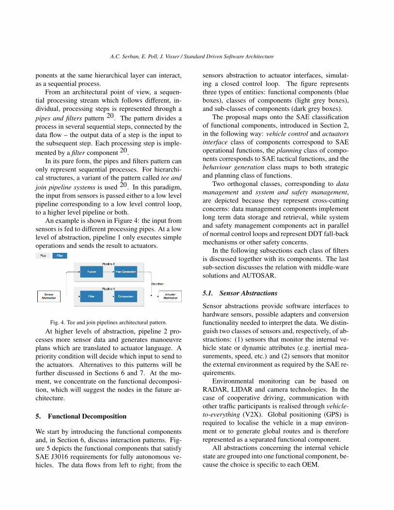
From an architectural point of view, a sequen-tial processing stream which follows different, in-dividual, processing steps is represented through apipes and filters pattern 20. The pattern divides aprocess in several sequential steps, connected by thedata flow – the output data of a step is the input tothe subsequent step. Each processing step is imple-mented by a filter component 20.
In its pure form, the pipes and filters pattern canonly represent sequential processes. For hierarchi-cal structures, a variant of the pattern called tee andjoin pipeline systems is used 20. In this paradigm,the input from sensors is passed either to a low levelpipeline corresponding to a low level control loop,to a higher level pipeline or both.
An example is shown in Figure 4: the input fromsensors is fed to different processing pipes. At a lowlevel of abstraction, pipeline 1 only executes simpleoperations and sends the result to actuators.
Fig. 4. Tee and join pipelines architectural pattern.
At higher levels of abstraction, pipeline 2 pro-cesses more sensor data and generates manoeuvreplans which are translated to actuator language. Apriority condition will decide which input to send tothe actuators. Alternatives to this patterns will befurther discussed in Sections 6 and 7. At the mo-ment, we concentrate on the functional decomposi-tion, which will suggest the nodes in the future ar-chitecture.
5. Functional Decomposition
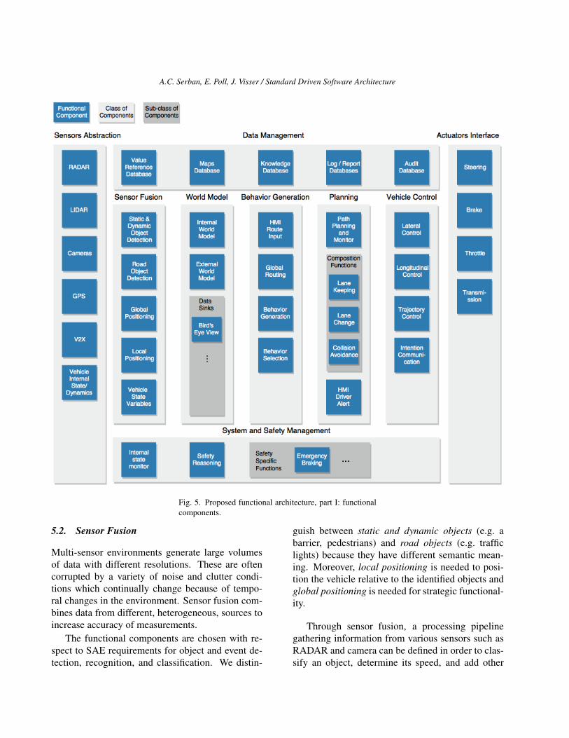
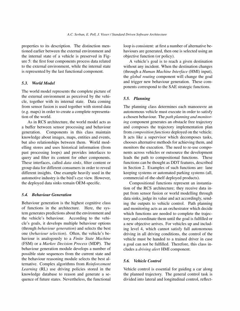
We start by introducing the functional componentsand, in Section 6, discuss interaction patterns. Fig-ure 5 depicts the functional components that satisfySAE J3016 requirements for fully autonomous ve-hicles. The data flows from left to right; from the
sensors abstraction to actuator interfaces, simulat-ing a closed control loop. The figure representsthree types of entities: functional components (blueboxes), classes of components (light grey boxes),and sub-classes of components (dark grey boxes).
The proposal maps onto the SAE classificationof functional components, introduced in Section 2,in the following way: vehicle control and actuatorsinterface class of components correspond to SAEoperational functions, the planning class of compo-nents corresponds to SAE tactical functions, and thebehaviour generation class maps to both strategicand planning class of functions.
Two orthogonal classes, corresponding to datamanagement and system and safety management,are depicted because they represent cross-cuttingconcerns: data management components implementlong term data storage and retrieval, while systemand safety management components act in parallelof normal control loops and represent DDT fall-backmechanisms or other safety concerns.
In the following subsections each class of filtersis discussed together with its components. The lastsub-section discusses the relation with middle-waresolutions and AUTOSAR.
5.1. Sensor Abstractions
Sensor abstractions provide software interfaces tohardware sensors, possible adapters and conversionfunctionality needed to interpret the data. We distin-guish two classes of sensors and, respectively, of ab-stractions: (1) sensors that monitor the internal ve-hicle state or dynamic attributes (e.g. inertial mea-surements, speed, etc.) and (2) sensors that monitorthe external environment as required by the SAE re-quirements.
Environmental monitoring can be based onRADAR, LIDAR and camera technologies. In thecase of cooperative driving, communication withother traffic participants is realised through vehicle-to-everything (V2X). Global positioning (GPS) isrequired to localise the vehicle in a map environ-ment or to generate global routes and is thereforerepresented as a separated functional component.
All abstractions concerning the internal vehiclestate are grouped into one functional component, be-cause the choice is specific to each OEM.
A.C. Serban, E. Poll, J. Visser / Standard Driven Software Architecture
Fig. 5. Proposed functional architecture, part I: functionalcomponents.
5.2. Sensor Fusion
Multi-sensor environments generate large volumesof data with different resolutions. These are oftencorrupted by a variety of noise and clutter condi-tions which continually change because of tempo-ral changes in the environment. Sensor fusion com-bines data from different, heterogeneous, sources toincrease accuracy of measurements.
The functional components are chosen with re-spect to SAE requirements for object and event de-tection, recognition, and classification. We distin-
guish between static and dynamic objects (e.g. abarrier, pedestrians) and road objects (e.g. trafficlights) because they have different semantic mean-ing. Moreover, local positioning is needed to posi-tion the vehicle relative to the identified objects andglobal positioning is needed for strategic functional-ity.
Through sensor fusion, a processing pipelinegathering information from various sensors such asRADAR and camera can be defined in order to clas-sify an object, determine its speed, and add other
A.C. Serban, E. Poll, J. Visser / Standard Driven Software Architecture
properties to its description. The distinction men-tioned earlier between the external environment andthe internal state of a vehicle is preserved in Fig-ure 5: the first four components process data relatedto the external environment, while the internal stateis represented by the last functional component.
5.3. World Model
The world model represents the complete picture ofthe external environment as perceived by the vehi-cle, together with its internal state. Data comingfrom sensor fusion is used together with stored data(e.g. maps) in order to create a complete representa-tion of the world.
As in RCS architecture, the world model acts asa buffer between sensor processing and behaviourgeneration. Components in this class maintainknowledge about images, maps, entities and events,but also relationships between them. World mod-elling stores and uses historical information (frompast processing loops) and provides interfaces toquery and filter its content for other components.These interfaces, called data sinks, filter content orgroup data for different consumers in order to revealdifferent insights. One example heavily used in theautomotive industry is the bird’s eye view. However,the deployed data sinks remain OEM-specific.
5.4. Behaviour Generation
Behaviour generation is the highest cognitive classof functions in the architecture. Here, the sys-tem generates predictions about the environment andthe vehicle’s behaviour. According to the vehi-cle’s goals, it develops multiple behaviour options(through behaviour generation) and selects the bestone (behaviour selection). Often, the vehicle’s be-haviour is analogously to a Finite State Machine(FSM) or a Markov Decision Process (MDP). Thebehaviour generation module develops a number ofpossible state sequences from the current state andthe behaviour reasoning module selects the best al-ternative. Complex algorithms from ReinforcementLearning (RL) use driving policies stored in theknowledge database to reason and generate a se-quence of future states. Nevertheless, the functional
loop is consistent: at first a number of alternative be-haviours are generated, then one is selected using anobjective function (or policy).
A vehicle’s goal is to reach a given destinationwithout any incident. When the destination changes(through a Human Machine Interface (HMI) input),the global routing component will change the goaland trigger new behaviour generation. These com-ponents correspond to the SAE strategic functions.
5.5. Planning
The planning class determines each manoeuvre anautonomous vehicle must execute in order to satisfya chosen behaviour. The path planning and monitor-ing component generates an obstacle free trajectoryand composes the trajectory implementation planfrom composition functions deployed on the vehicle.It acts like a supervisor which decomposes tasks,chooses alternative methods for achieving them, andmonitors the execution. The need to re-use compo-nents across vehicles or outsource the developmentleads the path to compositional functions. Thesefunctions can be thought as DDT features, describedin Section 2. Examples of such functions are: lanekeeping systems or automated parking systems (all,commercial of-the-shelf deployed products).
Compositional functions represent an instantia-tion of the RCS architecture; they receive data in-put from sensor fusion or world modelling throughdata sinks, judge its value and act accordingly, send-ing the outputs to vehicle control. Path planningand monitoring acts as an orchestrator which decidewhich functions are needed to complete the trajec-tory and coordinate them until the goal is fulfilled ora new objective arrives. For vehicles up and includ-ing level 4, which cannot satisfy full autonomousdriving in all driving conditions, the control of thevehicle must be handed to a trained driver in casea goal can not be fulfilled. Therefore, this class in-cludes a driving alert HMI component.
5.6. Vehicle Control
Vehicle control is essential for guiding a car alongthe planned trajectory. The general control task isdivided into lateral and longitudinal control, reflect-
A.C. Serban, E. Poll, J. Visser / Standard Driven Software Architecture
ing the SAE requirements for operational functions.This allows the control system to independently dealwith vehicle characteristics (such as maximum al-lowable tire forces, maximum steering angles, etc.)and with safety-comfort trade-off analysis. The tra-jectory control block takes a trajectory (generated atthe path planning and monitoring level) as input andcontrols the lateral and longitudinal modules. Thetrajectory represents a future desired state given byone of the path planning compositional functions.For example, if a lane-change is needed, the tra-jectory will represent the desired position in termsof coordinates and orientation, without any informa-tion about how the acceleration, steering or brakingwill be performed. The longitudinal control algo-rithm receives the target longitudinal state (such asbrake until 40 km/h) and decides if the action will beperformed by accelerating, braking, reducing throt-tle, or using the transmission module (i.e. enginebraking). The lateral control algorithm computesthe target steering angle given the dynamic prop-erties of a vehicle and the target trajectory. If thetrajectory includes a change that requires signalling,the communication mechanisms will be triggeredthrough the intention communication module.
5.7. Actuator Interfaces
The actuator interface modules transform data com-ing from vehicle control layer to actuator com-mands. The blocks in Figure 5 represent the basicinterfaces for longitudinal and lateral control.
5.8. Data Management
Data will at the centre of autonomous vehicles 21.In spite of the fact that most data requires real-timeprocessing, persistence is also needed. These con-cerns are represented using the data managementclass of components. Global localisation featuresrequire internal maps storage; intelligent decisionand pattern recognition algorithms require trainedmodels (knowledge database); internal state report-ing requires advanced logging mechanisms (loggingdatabase). The logging-report databases are alsoused to store data needed to later tune and improveintelligent algorithms. Moreover, an audit database
keeps authoritative logs (similar to black boxes inplanes) that can be used to solve liability issues. Inorder to allow dynamic deployable configurationsand any change in reference variables (e.g. a cali-bration or a decisional variable) a value referencedatabase is included.
5.9. System and Safety Management
The system and safety management block handlesfunctional safety mechanisms (fault detection andmanagement) and traffic safety concerns. It is an in-stantiation of the separated safety pattern 22 wherethe division criteria split the control system from thesafety operations. Figure 5 only depicts componentsthat spot malfunctions and trigger safety behaviour(internal state monitor, equivalent to a watch dog),but not redundancy mechanisms. The latter imple-ment partial or full replication of functional compo-nents. Moreover, safety specific functions deployedby the OEM to increase traffic safety are distinctlyrepresented. At this moment they are an indepen-dent choice of each OEM.
As the level of automation increases, it is nec-essary to take complex safety decisions. Startingwith level 3, the vehicle becomes fully responsiblefor traffic safety. Therefore, algorithms capable offull safety reasoning and casualty minimisation areexpected to be deployed. While it is not yet clearhow safety reasoning will be standardised and im-plemented in future vehicles, such components willsoon be mandatory 23. An overview of future safetychallenges autonomous vehicles face is illustratedin 24. With respect to the separated safety pattern, inFigure 5 safety reasoning components are separatedfrom behaviour generation.
5.10. AUTOSAR Context
AUTOSAR is a consortium between OEM and com-ponent suppliers which supports standardisation ofthe software infrastructure needed to integrate andrun automotive software. This paper does not ad-vocate for or against AUTOSAR. The adoption anduse of this standard is the choice of each OEM.However, due to its popularity, we consider manda-tory to position the work in the standard’s con-
A.C. Serban, E. Poll, J. Visser / Standard Driven Software Architecture
text. Given AUTOSAR, the functional componentsin Figure 5 represent AUTOSAR software compo-nents. The interfaces between components can bespecified through AUTOSAR’s standardised inter-face definitions. At the moment, the level of abstrac-tion presented in this paper does not include soft-ware interface.
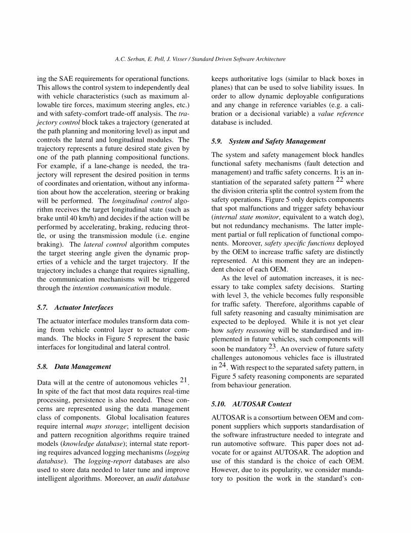
6. Interactions Between Components
As mentioned in Section 4, the components in Fig-ure 5 act as a hierarchical control structure, wherethe level of abstraction and cognition increases withthe hierarchical level, mapping on the SAE clas-sification of functional components. Componentslower in the hierarchy handle less complex taskssuch as operational functions, while higher compo-nents handle planning and strategic objectives (e.g.global routing or trajectory planning).
We propose the use of pipe-and-filter patternfor component interactions in flat control structures(same hierarchical level) and the use of tee-and-joinpipelines to represent the hierarchy. In a hierarchi-cal design, lower level components offer services toadjacent upper level components. However, the datainputs are often the same. A high level representa-tion of the system, through the tee-and-join pipelinespattern is illustrated in Figure 6. The grey boxes rep-resent processing pipelines and the blue ones repre-sent components classes.
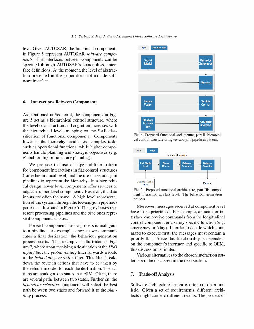
For each component class, a process is analogousto a pipeline. As example, once a user communi-cates a final destination, the behaviour generationprocess starts. This example is illustrated in Fig-ure 7, where upon receiving a destination at the HMIinput filter, the global routing filter forwards a routeto the behaviour generation filter. This filter breaksdown the route in actions that have to be taken bythe vehicle in order to reach the destination. The ac-tions are analogous to states in a FSM. Often, thereare several paths between two states. Further on, thebehaviour selection component will select the bestpath between two states and forward it to the plan-ning process.
Fig. 6. Proposed functional architecture, part II: hierarchi-cal control structure using tee-and-join pipelines pattern.
Fig. 7. Proposed functional architecture, part III: compo-nent interaction at class level. The behaviour generationprocess.
Moreover, messages received at component levelhave to be prioritised. For example, an actuator in-terface can receive commands from the longitudinalcontrol component or a safety specific function (e.g.emergency braking). In order to decide which com-mand to execute first, the messages must contain apriority flag. Since this functionality is dependenton the component’s interface and specific to OEM,this discussion is limited.
Various alternatives to the chosen interaction pat-terns will be discussed in the next section.
7. Trade-off Analysis
Software architecture design is often not determin-istic. Given a set of requirements, different archi-tects might come to different results. The process of

A.C. Serban, E. Poll, J. Visser / Standard Driven Software Architecture
weighting alternatives and selecting the most appro-priate decisions is called trade-off analysis. Severaldecisions in this paper could be taken differently.Therefore, in this section we present several alter-natives to our decisions and weight their advantagesand disadvantages.
We will start from the underlying assumption ofthis paper – that we can derive a set of valid require-ments from the SAE J3016 automotive standard. Asmentioned in Section 2, the purpose of this stan-dard is not to provide a complete definition of au-tonomy, but rather a minimal illustration of the func-tions needed in order to achieve it. It is meant toguide the process, and not exhaustively describe it.However, we find this information sufficient for ourgoals, because any functionality on top of the mini-mal requirements remains the choice of each OEM.
The second decision to be questioned is the useof NIST RCS architecture as a reference architec-ture for our work. An in-depth comparison withother works was presented in Section 4, however, wehereby present the trade-offs that come with choos-ing this reference architecture. Although it has thepower to clearly discriminate between reactive anddeductive components and is general enough to rep-resent both types of components, this reference ar-chitecture can be sometimes too complex for simplenodes.
In order to properly represent simple functions,from the operational class, one does not need a com-plex world model or behaviour generator modules.In some components they might miss altogether.However, the architecture does not impose any con-straints on the complexity of the world model. Thus,with limited world modelling or behaviour gener-ation module the architecture can easily representvery simple control loops such as value compara-tors. Moreover, when compared to other proposals,this reference model allows each individual nodesto have a level of reasoning – while in other onlycomponents higher in a hierarchy are responsible forplanning. This comes as a benefit for the automotivesoftware development life-cycle and for the compo-sitional functions we represented in the architecture.
We expect OEM to maintain their status oftechnology integrators and outsource more complex
functionality to their suppliers – such as completelane keeping or collision avoidance systems. Thesesystems can easily be implemented as RCS nodesand integrated in the overall architecture.
We find the RCS model broad enough to al-low the development of complex functionality, butsometimes too complex for simple functions – atrade-off that can be easily overcome by simpli-fying each block of the architecture in the lattercase. A more expressive alternative would be topropose RCS nodes of different complexity – withlower level nodes that can replace world modellingonly with value judgement. This decision must beweighted independently, as it might add clutter andother trade-offs when deciding which type of nodeshould one choose for each component.
A third trade-off clearly regards the functionaldecomposition. Although we aim to atomically de-compose every function and represent each sub-component individually, there is no way to prove thisis the correct way. New market trends foresee theadoption of system-on-a-chip circuits that integratemore and more components. Technologies such asMobilEye 25 aim to group several functions on adedicated chip. In such scenarios, sensor abstrac-tions and fusion layers could be merged. However,the functions implemented by such circuits will stillresemble our proposal. For example, even thoughthe sensor abstraction layer compresses to one com-ponent, all the functionality at the sensor fusionlayer still have to be implemented because static, dy-namic or road objects detection is absolutely manda-tory for autonomous driving. Therefore, our atomicdecomposition is able to represent these evolutions.
A fourth trade-off to be considered concerns thechoice for component interaction patterns. Severalalternatives to the tee and join pipelines pattern havebeen considered. One clear alternative is to use alayered architecture – where the functional compo-nents are grouped in a hierarchy and function callscan be made from higher layers to lower ones 4.However, this choice will constrain the possible in-teractions between components, thus limiting thedesign. At first, because each layer will encapsu-late some components, it will be impossible to re-

A.C. Serban, E. Poll, J. Visser / Standard Driven Software Architecture
use or re-orchestrate them in other processes. Sec-ondly, because the function calls at lower layers arerequired to come from upper layers, thus limitingeven more the design.
Another alternative is to use a component basedarchitecture, where all the components rest at thesame hierarchical layer and any component cancommunicate with all others. This pattern seems abetter fit for the automotive domain, where differentcomponents are deployed on various ECU and theycommunicate through a bus. However, it is unableto represent hierarchical reasoning.
We argue that the tee and join pattern is equiv-alent to the component based architecture, but hasthe ability to represent hierarchical processes. Thisis because from a component, one can easily begin anew pipeline with any other components. If only thepipes and filter pattern was considered, than the de-sign would be much limited. However, by giving theability to re-orchestrate filters in different pipelines,the tee and join pipelines pattern can easily representany kind of processes, either flat or hierarchical.
In this scenario one can define flat processes,similar to component based orchestration, but alsohierarchical processes (similar to the hierarchicalfunctional classes introduced in Section 3). The onlything to consider is a processing priority - which de-fines which pipelines should execute first.
8. Discussion
Software architects evaluate both the functional suit-ability of an architecture and non functional proper-ties such as performance or maintainability 26. Inthis paper we are only interested in functional suit-ability and completeness with respect to SAE J3016requirements. However, we find of interest to dis-cuss two other important aspects: the position of theproposed architecture with respect to (1) the auto-motive software development life cycle and (2) theISO 26262 standard that regulates functional safety.Later, in Section 9, we provide a comparison withexisting literature.
8.1. Incremental development and componentreuse
The SAE classification presented in Section 2 showsan incremental transition from partially automatedto fully autonomous vehicles. The functional divi-sion of software components should respect this in-cremental transition. Moreover, the OEM softwaredevelopment life-cycle and preference for outsourc-ing must be taken into account.
As mentioned in Section 2, DDT automation isanalogous to deploying and orchestrating enoughdriving automation features in order to satisfy alldriving conditions (ODD) in which a human candrive. This assumption employs two developmentpaths:
1. the deployment of new software componentsspecific to new DDT features or
2. updating a driving feature with enhancedfunctionality.
In Figure 5, new DDT features represent newcompositional functions specific to path planning.The use of composition functions enables incremen-tal and distributed development at the cost of in-creased complexity for path planning and monitor.These components can be commercial-of-the-shelfproducts that can easily be outsourced to tier onesuppliers.
Behaviour generation improvements are solvedthrough knowledge database updates. The V2Xcomponent interfaces with the external world, there-fore, updates can be pushed through this component.In most cases, the updates will target the knowledgeor value reference databases.
8.2. Functional safety
The automotive industry has high functional safetyconstraints imposed by the mandatory adherence toISO 26262 7. The objective of functional safety isto avoid any injuries or malfunctions of componentsin response to inputs, hardware or environmentalchanges. Error detection and duplication of safetycritical components are mechanisms suggested by

A.C. Serban, E. Poll, J. Visser / Standard Driven Software Architecture
ISO 26262. In this proposal, we represent the func-tional component specific to error detection, how-ever, omit to represent any redundancy or duplicatedcomponents.
We also aim to fulfil a gap in the ISO 26262 stan-dard, with regards to autonomous vehicles: safetyreasoning 24. To this moment it is not clear howautonomous vehicles will behave in case an acci-dent can not be avoided and which risk to minimise.However, it is expected for future safety standards toinclude specification for safety behaviour.
9. Related Work
As mentioned in Section 4, the transition to auto-mated and autonomous vehicles lies at the intersec-tion between two research fields with a rich his-tory in software engineering and architecture: au-tonomous systems and automotive. The basis of thefirst field were laid in Section 4, although we ex-pect many aspects of its evolution to influence theautonomous vehicles field. The pervasiveness ofcloud computing and communication that inspiredcloud robotics 27 is highly relevant for the automo-tive field. As vehicles begin to communicate and andeven distributively organize 28, 29, software archi-tecture plays an important role in satisfying qualityconstraints. New architectural paradigms, such asservice orientation 30 are already explored for someaspects in automotive 31, with little ties to the fieldof robotics. Moreover, recent trends in robotic ar-chitecture adaptation 32 are expected to follow inthe field of automotive.
Communication brings new constraints related tosecurity and trustworthiness, which have a direct im-pact on automotive software architecture 33. Al-though security is well studied in computer science,specialized techniques have been proposed in thefield of robotics 34, 35, 36, 37, which can be furtherextended to autonomous vehicles.
On the different tack, the field of automotiveengineering benefits from a rich history in design-ing, developing and deploying safety critical sys-tems able to operate for a long period of time.Software engineering in the automotive domain has
been recognized very early as playing an impor-tant role 2, 38, 39. From there on, each stage ofthe software development life-cycle has been stud-ied and naturally supported the evolution of automo-tive systems; ranging from requirements engineer-ing 40, 41, 42 to software assurance 43, 44 or soft-ware testing 45.
Software architecture design and system mod-eling plays a central role in the development pro-cess. Research in this direction focused on devel-oping tools to support architecture design, such asarchitectural description languages 46, 47, architec-ture views 48, 49, architectural standards 50 andeven standardization of architectural styles and in-terfaces, as in the case of AUTOSAR 51.
Moreover, automotive engineering has strongties with model-driven engineering 52; in de-veloping 53, maintaining 54 and testing mod-els 55, 56, 57. The impact of tight safety require-ments on software architecture has also been ana-lyzed in literature 58, 59.
However, the software needed to increase thelevel of autonomy is expected to have a big impacton all disciplines of automotive software engineer-ing. At first, the shift from purely deterministic soft-ware components to probabilistic ones where classi-cal verification methods do not scale will have a bigimpact in the way software is designed 60. More-over, well known vulnerabilities of machine learningalgorithms have to be considered early in the designphase 61, 62. Next generation automotive architec-tures take into consideration moving to more cen-tralized models, with high band Ethernet communi-cation and networks closer to computer networks 63.
We further focus on literature proposing func-tional and reference architectures starting with level3, since level 2 vehicles only automate lateral andlongitudinal control. A historical review of level 2systems is presented in 64.
Behere et al. introduce a functional reference ar-chitecture intended to level 5 vehicles 1. In this pro-posal, the authors make a clear distinction betweencognitive and vehicle platform functionality, simi-lar to the classification in tactical and operational

A.C. Serban, E. Poll, J. Visser / Standard Driven Software Architecture
SAE classes. However, the functional representa-tion groups several different functions in commoncomponents. For example, longitudinal and latitudi-nal control of the vehicle, equivalent to acceleration,breaking and steering are grouped in only one com-ponent, although they represent different concernsand are typically deployed differently.
The decision and control block 1. responsiblefor trajectory reasoning, selection and implementa-tion is equivalent to the behaviour generation andplanning class of components from Figure 5. How-ever, the authors only define trajectory generation asa separate component, leading to a rough represen-tation of functional components. It is not clear howthis block handles all functionality and what type ofdecisions it makes; strategic or tactic. For example,will the same component be responsible for decid-ing if a vehicle should turn left at the first road-cross,over-take the car up front and generate a trajectoryfor executing all maneuvers? These hierarchical de-cisions correspond to a transition from strategic totactical functions (as indicated by SAE) and shouldbe awarded separate components. Moreover, impor-tant components responsible for interactions, suchas HMI, or for environmental understanding, suchas object detection, are ignored from the proposal 1.
A proliferation of competitions in constrainedor unconstrained environments resulted in differentdesigns of autonomous vehicles. The most popu-lar one, the DARPA Grand Challenge, started withautonomous vehicles operating in desert conditionsand later evolved to urban environments (throughthe DARPA Urban Challenge). During the first com-petition, although the environment was challeng-ing, the behaviour of the vehicle was relatively sim-ple and could be modeled as a simple state ma-chine 65. This is in contrast to challenges posed byreal life traffic scenarios, in which the environmenthas higher variability and requires more complex be-haviours.
Nevertheless, the initial architectures used in thecompetition bear similarities with modern architec-tures for autonomous vehicles. The winning vehicleused a layer-based architecture as described in Sec-tion 4 13, with hierarchical increasing complexityfrom sensor interfaces to perception (understanding
the environment) and planning 66. We find a goodrepresentation of the SAE J3016 classes of compo-nents mentioned in Section 2, although there is alarge overlap between strategic and tactical compo-nents (a normal consequence of the complexity ofthe environment).
An interesting (and unique) architectural choiceis to explicitly represent the components responsi-ble for data logging and storage, to emphasize theneed to think about data and treat data and softwareas the main innovation driver. This early choice rec-ognizes the need to separate the constraints relatedto data storage from the functional components thatmay log the data; a perspective often missed in laterarchitectures.
Given the constrained environment, the proposalwas not concerned with destination routing or anydriving assistance or safety features, such as lane as-sist or emergency braking. Therefore, the DDT fea-tures presented are limited, constraining the archi-tecture’s suitability to more complex environments.Nonetheless, the work shows a high level of matu-rity when reasoning about processing pipelines andtask distribution.
The second competition, the Darpa Urban Chal-lenge, saw increased interest in computer vi-sion based perception algorithms, but also a bet-ter representation of behaviour generation func-tions 67, 68, 69, 67, 70. Moreover, an increase incomputing power and centralization can be observedin all proposals.
Building on the same architecture from the grandchallenge 66, Montemerlo et al. 69 increased theabstraction of the perception layer to a fusion layersimilar to the one represented in Figure 5. Static anddynamic obstacle tracking (although constrained toa list by the complexity of the operational domain)are now first class citizens of the architecture. Sim-ilarly, since the vehicle operates in normal road en-vironments, the importance of local positioning isrecognized.
Several teams focused heavily on computer vi-sion and threat such algorithms at a differentlayer 70, 71, although use fusion as an intermediarylayer between perception and reasoning. The archi-tecture presented by Patz et al. 70 provide a clear
A.C. Serban, E. Poll, J. Visser / Standard Driven Software Architecture
distinction between strategic and functional com-ponents (through the intelligence and planning lay-ers) and represents a good fit for the SAE class ofcomponents. Other architectures, such as 68 or 71
have an entangled representation between strategicand tactical components because they focus on task-specific components. However, if we abstract fromtask-specific components, we can find a balancedrepresentation of the components suggested by theSAE standard. What misses is a clear distinctionbetween the hierarchical levels of abstractions, cor-responding to the semantic understanding of the en-vironment needed to perform a task.
For another autonomous vehicles competitionheld in Korea, Jo et al. 72, 73 introduce a morecomplex architecture. The proposal comes one stepcloser to a general architecture, given broader com-petition goals. The model contains sensor abstrac-tions, fusion, behaviour and path planning, vehiclecontrol and actuator interfaces. In this regard, it rep-resents similar concerns to Figure 5, without worldmodelling and HMI route inputs. Instead, the be-haviour planning component integrates data com-ing from sensors in order to generate an executionplan. Since the goal of the competition was limited,both localisation and behaviour reasoning compo-nents are restricted (a finite state machine with only8 possible states that can stop for a barrier, detectsplit road, etc.). The artefact successfully representsoperational and tactical functions. Moreover, Jo etal. divide, for the first time, the concerns from be-haviour and from path planning, thus obtaining sev-eral levels of cognition and control. The study alsoreveals important details for in-vehicle ECU deploy-ment and a mapping to AUTOSAR.
In a different competition, called the Grand Co-operative Driving Challenge, teams raced to developvehicles that can successfully exchange informationand form platoons 75, 76, 77, 78, 79. Although theenvironmental monitoring requires less semantic un-derstanding, the representation of tactical and oper-ational function across the proposed architectures issimilar to the division made by SAE J3016. In par-ticular, the architecture presented in 79 uses the tee-and-join pipelines patter introduced above.
An important contribution from industry re-
search is the work of Ziegler et al. 74 at Mer-cedes Benz, later evolved to cooperative driving 78.Although it has a descriptive purpose, the systemoverview is the most similar to the SAE suggestionand the proposal introduced in this paper. It featuresa clear distinction between object recognition, local-isation, motion planning and vehicle control, anal-ogous to sensor fusion, behaviour generation, plan-ning and vehicle control in Figure 5. Another impor-tant contribution is the representation of data storagefunctionality for digital maps and reactive compo-nents such as emergency braking.
Overall, we observe two approaches in the lit-erature: (1) a high level overview of system com-ponents where the functionality is not clearly di-vided and (2) proofs-of-concept from experimentswith autonomous features or competition with lim-ited operational domain. The lessons learned fromparticipating in different competitions are very valu-able. Most architectures considered here have alarge overlap with the SAE J3016 description andclasses of functions, with the current proposal andbetween themselves. The overlap between them-selves reveals an intrinsic set of components withoutwhich autonomy will not be possible. They repre-sent the least can be done to automate some func-tions. The disadvantage of developing with concretescenarios in mind is the lower level of abstractionneeded to develop a reference architecture.
In this paper we try to overcome this advan-tage using a standard driven and more fine-grainedfunctional decomposition. Several other constraints,such as the automotive software development life-cycle or the role of the OEMs are taken into account,leading to a more general proposal. Moreover, sincethe ultimate goal is to achieve level 5 autonomy, thefunctional decomposition takes into account the se-mantics of the information consumed, which natu-rally leads to incremental, hierarchical, abstractions.
10. Conclusions and Future Research
We introduce a functional software architecture forfully autonomous vehicles. Since the automotive in-dustry is highly standardised, we follow the func-tional requirements from an automotive standard

A.C. Serban, E. Poll, J. Visser / Standard Driven Software Architecture
which defines multiple levels of driving automationand includes functional definitions for each level.
During the architecture design, we aim to respectthe incremental development process of autonomousvehicles and the distributed software developmentprocess specific to the automotive industry. The finalartefact represents an automotive specific instantia-tion of the NIST RCS reference architecture for real-time, intelligent, control systems. We use the pipe-and-filter architectural pattern for component inter-action and the tee-and-join pipeline pattern to repre-sent a hierarchical control structure. Several trade-offs and alternative decisions are discussed withinthe paper.
Future work might include refinement throughexpert opinion. Later steps consider component in-terface design, a choice for hardware architecture,functional component distribution across ECUs andcomponent distribution inside local networks in or-der to satisfy security requirements.
References
[1] S. Behere and M. Torngren, “A functional ref-erence architecture for autonomous driving,”Information and Software Technology, vol. 73,pp. 136–150, 2016.
[2] M. Broy, “Challenges in automotive softwareengineering,” in International Conference onSoftware Engineering (ICSE’06), pp. 33–42,ACM, 2006.
[3] Society of Automotive Engineers (SAE),“J3016,” SAE international taxonomy and defi-nitions for terms related to on-road motor vehi-cle automated driving systems,” levels of driv-ing automation, 2014.
[4] M. Staron, Automotive Software Architectures,vol. 1. Springer International Publishing, 2017.
[5] D. Garlan, “Software architecture: a roadmap,”in Conference on The Future of Software Engi-neering (ICSE’00), pp. 91–101, ACM, 2000.
[6] A. Serban, E. Poll, and J. Visser, “A stan-dard driven software architecture for fully au-
tonomous vehicles,” Proceedings of WASAWorkshop, 2018.
[7] International Organization for Standardization(ISO), “ISO standard 26262:2011 Road vehi-cles - Functional safety,” 2011.
[8] N. B. Ruparelia, “Software development life-cycle models,” ACM SIGSOFT Software En-ginering Notes, vol. 35, no. 3, pp. 8–13, 2010.
[9] R. Wieringa, “Design science methodology:principles and practice,” in International Con-ference on Software Engineering (ICSE’10),pp. 493–494, ACM, 2010.
[10] R. Horowitz and P. Varaiya, “Control design ofan automated highway system,” Proceedingsof the IEEE, vol. 88, no. 7, pp. 913–925, 2000.
[11] P. Maes, “Behavior-based artificial intelli-gence,” in Proceedings of the Fifteenth An-nual Meeting of the Cognitive Science Society,pp. 74–83, 1993.
[12] J. S. Albus, “The NIST real-time control sys-tem (RCS): an approach to intelligent systemsresearch,” Journal of Experimental & Theo-retical Artificial Intelligence, vol. 9, no. 2-3,pp. 157–174, 1997.
[13] E. Gat and R. P. Bonnasso, “On three-layer ar-chitectures,” Artificial intelligence and mobilerobots, vol. 195, p. 210, 1998.
[14] N. Muscettola, G. A. Dorais, C. Fry, R. Levin-son, and C. Plaunt, “Idea: Planning at thecore of autonomous reactive agents,” in NASAWorkshop on Planning and Scheduling forSpace, 2002.
[15] K. Konolige, K. Myers, E. Ruspini, and A. Saf-fiotti, “The Saphira architecture: A design forautonomy,” Journal of Experimental & Theo-retical Artificial Intelligence, vol. 9, no. 2-3,pp. 215–235, 1997.
[16] R. Volpe, I. Nesnas, T. Estlin, D. Mutz, R. Pe-tras, and H. Das, “The CLARAty architec-ture for robotic autonomy,” in IEEE AerospaceConference, vol. 1, pp. 121–132, IEEE, 2001.

A.C. Serban, E. Poll, J. Visser / Standard Driven Software Architecture
[17] “An architectural blueprint for autonomic com-puting,” tech. rep., IBM, 2006. White paper.Fourth edition.
[18] N. J. Nilsson, Principles of artificial intelli-gence. Morgan Kaufmann, 2014.
[19] J. S. Albus and W. Rippey, “Rcs: A referencemodel architecture for intelligent control,” inFrom Perception to Action Conference, 1994.,Proceedings, pp. 218–229, IEEE, 1994.
[20] F. Buschmann, K. Henney, and D. C. Schmidt,Pattern-oriented Software Architecture, vol. 5.John Wiley & Sons, 2007.
[21] M. Johanson, S. Belenki, J. Jalminger, M. Fant,and M. Gjertz, “Big automotive data: Lever-aging large volumes of data for knowledge-driven product development,” in Big Data (BigData), 2014 IEEE International Conferenceon, pp. 736–741, IEEE, 2014.
[22] J. Rauhamaki, T. Vepsalainen, and S. Kuikka,“Functional safety system patterns,” in Pro-ceedings of VikingPLoP, Tampere Universityof Technology, 2012.
[23] J.-F. Bonnefon, A. Shariff, and I. Rahwan,“The social dilemma of autonomous vehicles,”Science, vol. 352, no. 6293, 2016.
[24] A. Serban, E. Poll, and J. Visser, “Tacticalsafety reasoning. a case for autonomous vehi-cles.,” Proceedings of Ca2V Workshop, 2018.
[25] N. Mobileye, “Introduces eyeq vision system-on-a-chip high performance,” Low Cost Break-through for Driver Assistance Systems, De-troit, Michigan, 2004.
[26] L. Dobrica and E. Niemela, “A survey onsoftware architecture analysis methods,” IEEETransactions on Software Engineering, vol. 28,no. 7, pp. 638–653, 2002.
[27] G. Hu, W. P. Tay, and Y. Wen, “Cloudrobotics: architecture, challenges and applica-tions,” IEEE network, vol. 26, no. 3, pp. 21–28,2012.
[28] A. C. Serban, E. Poll, and J. Visser, “A secu-rity analysis of the etsi its vehicular communi-cations,” in International Conference on Com-puter Safety, Reliability, and Security, pp. 365–373, Springer, 2018.
[29] S. Garcıa, C. Menghi, P. Pelliccione, T. Berger,and R. Wohlrab, “An architecture for de-centralized, collaborative, and autonomousrobots,” in 2018 IEEE International Confer-ence on Software Architecture (ICSA), pp. 75–7509, IEEE, 2018.
[30] A. Koubaa, “Service-oriented software archi-tecture for cloud robotics,” arXiv preprintarXiv:1901.08173, 2019.
[31] S. Kugele, D. Hettler, and J. Peter, “Data-centric communication and containerizationfor future automotive software architectures,”in 2018 IEEE International Conference onSoftware Architecture (ICSA), pp. 65–6509,IEEE, 2018.
[32] J. Aldrich, D. Garlan, C. Kastner, C. Le Goues,A. Mohseni-Kabir, I. Ruchkin, S. Samuel,B. Schmerl, C. S. Timperley, M. Veloso, et al.,“Model-based adaptation for robotics soft-ware,” IEEE Software, vol. 36, no. 2, pp. 83–90, 2019.
[33] R. Ferrandez, Y. Dajsuren, P. Karkhanis,M. Funfrocken, and M. Pillado, “Modeling thec-its architectures: C-mobile case study,” inITS World Congress, 2018.
[34] V. M. Vilches, L. A. Kirschgens, A. B. Calvo,A. H. Cordero, R. I. Pison, D. M. Vilches,A. M. Rosas, G. O. Mendia, L. U. S. Juan, I. Z.Ugarte, et al., “Introducing the robot securityframework (rsf), a standardized methodologyto perform security assessments in robotics,”arXiv preprint arXiv:1806.04042, 2018.
[35] V. M. Vilches, E. Gil-Uriarte, I. Z. Ugarte,G. O. Mendia, R. I. Pison, L. A. Kirschgens,A. B. Calvo, A. H. Cordero, L. Apa, and

A.C. Serban, E. Poll, J. Visser / Standard Driven Software Architecture
C. Cerrudo, “Towards an open standard for as-sessing the severity of robot security vulner-abilities, the robot vulnerability scoring sys-tem (rvss),” arXiv preprint arXiv:1807.10357,2018.
[36] B. Dieber and B. Breiling, “Security consid-erations in modular mobile manipulation,” in2019 Third IEEE International Conference onRobotic Computing (IRC), pp. 70–77, IEEE,2019.
[37] I. Priyadarshini, “Cyber security risks inrobotics,” in Cyber Security and Threats: Con-cepts, Methodologies, Tools, and Applications,pp. 1235–1250, IGI Global, 2018.
[38] M. Broy, I. H. Kruger, A. Pretschner, andC. Salzmann, “Engineering automotive soft-ware,” Proceedings of the IEEE, vol. 95, no. 2,pp. 356–373, 2007.
[39] A. Pretschner, M. Broy, I. H. Kruger, andT. Stauner, “Software engineering for auto-motive systems: A roadmap,” in Future ofSoftware Engineering (FOSE’07), pp. 55–71,IEEE, 2007.
[40] M. Weber and J. Weisbrod, “Requirementsengineering in automotive development-experiences and challenges,” in ProceedingsIEEE Joint International Conference on Re-quirements Engineering, pp. 331–340, IEEE,2002.
[41] A. Vogelsang and S. Fuhrmann, “Why featuredependencies challenge the requirements en-gineering of automotive systems: An empir-ical study,” in 2013 21st IEEE InternationalRequirements Engineering Conference (RE),pp. 267–272, IEEE, 2013.
[42] M. Staron, “Requirements engineering for au-tomotive embedded systems,” in AutomotiveSystems and Software Engineering, pp. 11–28,Springer, 2019.
[43] Y. Luo, M. Van den Brand, L. Engelen, andM. Klabbers, “A modeling approach to support
safety assurance in the automotive domain,”in Progress in Systems Engineering, pp. 339–345, Springer, 2015.
[44] N. L. Fung, S. Kokaly, A. Di Sandro, R. Salay,and M. Chechik, “Mmint-a: a tool for auto-mated change impact assessment on assurancecases,” in International Conference on Com-puter Safety, Reliability, and Security, pp. 60–70, Springer, 2018.
[45] M. Markthaler, S. Kriebel, K. S. Salman,T. Greifenberg, S. Hillemacher, B. Rumpe,C. Schulze, A. Wortmann, P. Orth, andJ. Richenhagen, “Improving model-based test-ing in automotive software engineering,” in2018 IEEE/ACM 40th International Confer-ence on Software Engineering: SoftwareEngineering in Practice Track (ICSE-SEIP),pp. 172–180, IEEE, 2018.
[46] V. Debruyne, F. Simonot-Lion, and Y. Trin-quet, “East-adl—an architecture descriptionlanguage,” in IFIP World Computer Congress,TC 2, pp. 181–195, Springer, 2004.
[47] Y. Dajsuren, M. van den Brand, A. Serebrenik,and R. Huisman, “Automotive adls: a study onenforcing consistency through multiple archi-tectural levels,” in Proceedings of the 8th inter-national ACM SIGSOFT conference on Qual-ity of Software Architectures, pp. 71–80, ACM,2012.
[48] H. Gronninger, J. Hartmann, H. Krahn,S. Kriebel, L. Rothhart, and B. Rumpe, “Mod-elling automotive function nets with views forfeatures, variants, and modes,” arXiv preprintarXiv:1409.6628, 2014.
[49] Y. Dajsuren, C. M. Gerpheide, A. Serebrenik,A. Wijs, B. Vasilescu, and M. G. van denBrand, “Formalizing correspondence rules forautomotive architecture views,” in Proceed-ings of the 10th international ACM Sigsoft con-ference on Quality of software architectures,pp. 129–138, ACM, 2014.

A.C. Serban, E. Poll, J. Visser / Standard Driven Software Architecture
[50] M. Broy, M. Gleirscher, S. Merenda, D. Wild,P. Kluge, and W. Krenzer, “Toward a holisticand standardized automotive architecture de-scription,” Computer, vol. 42, no. 12, pp. 98–101, 2009.
[51] S. Furst, J. Mossinger, S. Bunzel, T. Weber,F. Kirschke-Biller, P. Heitkamper, G. Kinke-lin, K. Nishikawa, and K. Lange, “Autosar–aworldwide standard is on the road,” in 14th In-ternational VDI Congress Electronic Systemsfor Vehicles, Baden-Baden, vol. 62, 2009.
[52] J. Hutchinson, M. Rouncefield, and J. Whittle,“Model-driven engineering practices in indus-try,” in Proceedings of the 33rd InternationalConference on Software Engineering, pp. 633–642, ACM, 2011.
[53] J. Wan, A. Canedo, and M. A. Al Faruque,“Functional model-based design methodologyfor automotive cyber-physical systems,” IEEESystems Journal, vol. 11, no. 4, pp. 2028–2039, 2015.
[54] M. Volter, T. Stahl, J. Bettin, A. Haase, andS. Helsen, Model-driven software develop-ment: technology, engineering, management.John Wiley & Sons, 2013.
[55] Y. Dajsuren, M. G. Van Den Brand, A. Sere-brenik, and S. Roubtsov, “Simulink modelsare also software: Modularity assessment,” inProceedings of the 9th international ACM Sig-soft conference on Quality of software archi-tectures, pp. 99–106, ACM, 2013.
[56] E. Bringmann and A. Kramer, “Model-basedtesting of automotive systems,” in 2008 1stinternational conference on software testing,verification, and validation, pp. 485–493,IEEE, 2008.
[57] A. Petrenko, O. N. Timo, and S. Ramesh,“Model-based testing of automotive software:Some challenges and solutions,” in Proceed-ings of the 52nd Annual Design AutomationConference, p. 118, ACM, 2015.
[58] A. K. Saberi, Y. Luo, F. P. Cichosz, M. van denBrand, and S. Jansen, “An approach for func-tional safety improvement of an existing auto-motive system,” in 2015 Annual IEEE SystemsConference (SysCon) Proceedings, pp. 277–282, IEEE, 2015.
[59] A. K. Saberi, E. Barbier, F. Benders, andM. Van Den Brand, “On functional safetymethods: A system of systems approach,” in2018 Annual IEEE International Systems Con-ference (SysCon), pp. 1–6, IEEE, 2018.
[60] A. C. Serban, “Designing safety critical soft-ware systems to manage inherent uncertainty,”in 2019 IEEE International Conference onSoftware Architecture Companion (ICSA-C),pp. 246–249, IEEE, 2019.
[61] A. C. Serban, E. Poll, and J. Visser, “Ad-versarial examples-a complete characterisa-tion of the phenomenon,” arXiv preprintarXiv:1810.01185, 2018.
[62] S. Ray, “Safety, security, and reliability: Theautomotive robustness problem and an archi-tectural solution,” in 2019 IEEE InternationalConference on Consumer Electronics (ICCE),pp. 1–4, IEEE, 2019.
[63] B. Zheng, H. Liang, Q. Zhu, H. Yu, and C.-W. Lin, “Next generation automotive architec-ture modeling and exploration for autonomousdriving,” in 2016 IEEE Computer Society An-nual Symposium on VLSI (ISVLSI), pp. 53–58,IEEE, 2016.
[64] A. Khodayari, A. Ghaffari, S. Ameli, andJ. Flahatgar, “A historical review on lateraland longitudinal control of autonomous vehi-cle motions,” ICMET, pp. 421–429, 2010.
[65] Q. Chen, U. Ozguner, and K. Redmill, “Ohiostate university at the 2004 darpa grand chal-lenge: developing a completely autonomousvehicle,” IEEE Intelligent Systems, vol. 19,no. 5, pp. 8–11, 2004.
[66] S. Thrun, M. Montemerlo, H. Dahlkamp,D. Stavens, A. Aron, J. Diebel, P. Fong,

A.C. Serban, E. Poll, J. Visser / Standard Driven Software Architecture
J. Gale, M. Halpenny, G. Hoffmann, et al.,“Stanley: The robot that won the darpa grandchallenge,” Journal of field Robotics, vol. 23,no. 9, pp. 661–692, 2006.
[67] C. Urmson, C. Baker, J. Dolan, P. Rybski,B. Salesky, W. Whittaker, D. Ferguson, andM. Darms, “Autonomous driving in traffic:Boss and the urban challenge,” AI magazine,vol. 30, no. 2, pp. 17–17, 2009.
[68] S. Kammel, J. Ziegler, B. Pitzer, M. Wer-ling, T. Gindele, D. Jagzent, J. Schroder,M. Thuy, M. Goebl, F. v. Hundelshausen, et al.,“Team annieway’s autonomous system for the2007 darpa urban challenge,” Journal of FieldRobotics, vol. 25, no. 9, pp. 615–639, 2008.
[69] M. Montemerlo, J. Becker, S. Bhat, et al., “Ju-nior: The Stanford entry in the urban chal-lenge,” Journal of Field Robotics, vol. 25,no. 9, pp. 569–597, 2008.
[70] B. J. Patz, Y. Papelis, R. Pillat, G. Stein, andD. Harper, “A practical approach to robotic de-sign for the darpa urban challenge,” Journalof Field Robotics, vol. 25, no. 8, pp. 528–566,2008.
[71] A. Bacha, C. Bauman, R. Faruque, M. Flem-ing, C. Terwelp, C. Reinholtz, D. Hong,A. Wicks, T. Alberi, D. Anderson, et al.,“Odin: Team victortango’s entry in the darpaurban challenge,” Journal of field Robotics,vol. 25, no. 8, pp. 467–492, 2008.
[72] K. Jo, J. Kim, D. Kim, C. Jang, and M. Sun-woo, “Development of autonomous car - partI,” IEEE Transactions on Industrial Electron-ics, vol. 61, no. 12, pp. 7131–7140, 2014.
[73] K. Jo, J. Kim, D. Kim, C. Jang, and M. Sun-woo, “Development of autonomous car - partII,” IEEE Transactions on Industrial Electron-ics, vol. 62, no. 8, pp. 5119–5132, 2015.
[74] J. Ziegler, P. Bender, M. Schreiber, H. Late-gahn, T. Strauss, C. Stiller, T. Dang, U. Franke,
N. Appenrodt, C. G. Keller, et al., “MakingBertha drive - an autonomous journey on a his-toric route,” IEEE ITS Magazine, vol. 6, no. 2,pp. 8–20, 2014.
[75] A. Geiger, M. Lauer, F. Moosmann, B. Ranft,H. Rapp, C. Stiller, and J. Ziegler, “Team an-nieway’s entry to the 2011 grand cooperativedriving challenge,” IEEE Transactions on In-telligent Transportation Systems, vol. 13, no. 3,pp. 1008–1017, 2012.
[76] L. Guvenc, I. M. C. Uygan, K. Kahraman,R. Karaahmetoglu, I. Altay, M. Senturk, M. T.Emirler, A. E. H. Karci, B. A. Guvenc, E. Al-tug, et al., “Cooperative adaptive cruise con-trol implementation of team mekar at the grandcooperative driving challenge,” IEEE Trans-actions on Intelligent Transportation Systems,vol. 13, no. 3, pp. 1062–1074, 2012.
[77] R. Kianfar, B. Augusto, A. Ebadighajari,U. Hakeem, J. Nilsson, A. Raza, R. S. Tabar,N. V. Irukulapati, C. Englund, P. Falcone,et al., “Design and experimental validation of acooperative driving system in the grand coop-erative driving challenge,” IEEE Transactionson Intelligent Transportation Systems, vol. 13,no. 3, pp. 994–1007, 2012.
[78] O. S. Tas, N. O. Salscheider, F. Poggen-hans, S. Wirges, C. Bandera, M. R. Zofka,T. Strauss, J. M. Zollner, and C. Stiller, “Mak-ing bertha cooperate–team annieway’s entry tothe 2016 grand cooperative driving challenge,”IEEE Transactions on Intelligent Transporta-tion Systems, vol. 19, no. 4, pp. 1262–1276,2017.
[79] R. Hult, F. E. Sancar, M. Jalalmaab, A. Vi-jayan, A. Severinson, M. Di Vaio, P. Falcone,B. Fidan, and S. Santini, “Design and experi-mental validation of a cooperative driving con-trol architecture for the grand cooperative driv-ing challenge 2016,” IEEE Transactions on In-telligent Transportation Systems, vol. 19, no. 4,pp. 1290–1301, 2018.